Advertisement
Quick Links
User's
Model MY40
Manual
Insulation Resistance Tester
This manual describes the specifications and handling precautions of the insulation resistans tester.
Before using this product, thoroughly read this manual to understand how to use it properly.
The following manuals, including this one, are provided as manuals for the MY40. Please read all manuals.
IM MY40-E:
Safety precautions, components and specifications etc. (this manual)
IM MY40-02EN:
Operation manual
IM MY40-S03-EN:
Sales in Each Country or Region
(Waste Electrical and Electronic Equipment, EU Battery Directive)
IM CROHS-MY40:
Document for China
IM MY40-93Z2:
Document for Korea
Contact information of Yokogawa offices worldwide is provided on the following sheet.
PIM 113-01Z2:
Inquiries
Store this manual in an easily accessible place
for quick reference.
9th Edition: October 2017 (YMI)
All Rights Reserved. Copyright ©
1996, Yokogawa M&C Corporation,
2015, Yokogawa Meters & Instruments Corporation,
2017, Yokogawa Test & Measurement Corporation
Model and Suffix Code
MODEL
SUFFIX
Specifications
MY40
Insulation Resistance Tester
Rating
-01
125 V/200 MΩ, 250 V/200 MΩ, 500 V/2000 MΩ, 1000 V/2000 MΩ
1.
Safety Precautions
This product is designed to be used by a person with specialized knowledge.
When operating the instrument, be sure to observe the cautionary notes given below to ensure correct and
safe use of the instrument. If you use the instrument in any way other than as instructed in this manual,
the instrument's protective measures may be impaired.
This manual is an essential part of the product; keep it a safe place for future reference.
YOKOGAWA is by no means liable for any damage resulting from use of the instrument in contradiction to
these cautionary notes.
The following safety symbols are used on the instrument and in this manual.
This symbol indicates that the operator must refer to an explanation in the user's manual
in order to avoid risk of injury or death of personnel or damage to the tester.
WARNING
Indicates a hazard that may result in the loss of life or serious injury of the user unless
the described instruction is abided by.
CAUTION
Indicates a hazard that may result in an injury to the user and/or physical damage to
the product or other equipment unless the described instruction is abided by.
NOTE
Indicates information that is essential for handling the instrument or should be noted in order to
familiarize yourself with the instrument's operating procedures and/or functions.
High-voltage Terminal
This symbol indicates a dangerous voltage level (terminals with voltagesexceeding
1000 volts must be so marked). Never touch the terminals.
AC Voltage
This symbol indicates the presence of an AC voltage.
Double Insulation
This symbol indicates double insulation.
■ Always observe the following instructions. Failure to do so may result in electric shock or
other dangers that may lead to serious injury or the loss of life.
WARNING
This instrument is a insulation resistance tester that can measure insulation resistance (AC voltage).
Do not use this instrument for other purpose.
Do not use the instrument if there is a problem with its physical appearance.
1. During Measurement of Insulation Resistance
• A high voltage is present at the probes. Do not touch the measured object or the earth or line terminal.
2. Immediately After Measurement of Insulation Resistance
• The probes or the measured object may remain highly charged.
Do not touch them immediately after the completion of measurement.
3. During Measurement of AC Voltages
• Do not press the MEAS key while measuring AC voltages.
• Voltage that exceeds the specified limit must not be applied to terminals.
4. Probes
• Use the probes supplied by Yokogawa with this tester.
• Do not use probes that have deteriorated or are defective.
• Remove the probes from the measured object before attaching/detaching the probes to/from the tester.
5. Insulation of Casing
• A puncture in the protective insulation may occur if there are any cracks or other damage in
the casing as a result of the instrument having been dropped or knocked against another object.
Do not use the instrument before taking the necessary remedial measures; ask the manufacturer to repair it.
6. The Measured Object
• Turn off the power to the measured object before you begin measuring insulation resistance.
• Avoid touching any electrified parts while using the tester in a location with live electricity.
Safety protectors such as rubber-insulated gloves should be worn to prevent electrical shock
when using the tester.
7. Operating Environment
• Do not operate the tester in an atmosphere where any flammable or explosive gas is present.
• Do not use the tester if there is condensation on it.
8. Do Not Remove the Casing or Disassemble
Do not open the case except when replacing batteries.
Only qualified YOKOGAWA personnel may remove the case and disassemble or alter the instrument.
Do not attempt to repair/modify the instrument yourself, as doing so is extremely dangerous.
CAUTION
• The instrument is for domestic use (Class B) and meets the electromagnetic compatibility requirements.
• To verify the instrument's functionality, check that the measured value is update after turning on the power.
If the measured value is not update, the reading will be incorrect and may lead to possible electrical shock
or personal injury.
■ Measurement Categories
Measurement category of the MY40
WARNING
The instrument is designed for measurement category III.
Do not use the instrument for measurements in locations falling that fall under measurement category IV.
List of worldwide contacts
Printed in China
IM MY40-E
9th Edition: Oct. 2017 (YMI)
Measurement category of the Probes
Line probe (98001)
With cap: 600 V CAT III
Earth probe (98002)
600 V CAT III
WARNING
A cap is provided on the tip of the line probe.
Use the line probe with the cap on for safety (safety standard: EN61010-031).
Measurement
Description
category
O
Other circuits that are not directly connected
(None, Other)
to MAINS.
CAT II
For measurements performed on circuits
directly connected to the low-voltage installation.
CAT III
For measurements performed
in the building installation.
CAT IV
For measurements performed
at the source of the low-voltage installation.
B3
2.
Measuring Functions and Additional Features
■ Measuring Functions
• Measuring the insulation resistance (four ratings)
125 V/ 200 MΩ, 250 V/ 200 MΩ, 500 V/ 2000 MΩ, 1000 V/ 2000 MΩ
• Measuring AC voltages (sine wave at 45 to 400 Hz)
• Measuring conductor resistances (0 to 400.0 Ω)
Continuity test (beeps for 40 Ω or less)
■ Additional Features
• Memory feature (data saving)
Up to 20 measured values of the insulation resistance for each rating can be saved to memory.
• Live-line alarm
When an AC voltage of 40 V or more is applied between the input terminals,
the ALARM LED flashes and the buzzer beeps (except during AC voltage measurement).
• Comparator
When a measured insulation resistance is less than the reference value setting,
the LOW mark appears and the buzzer beeps.
• HOLD feature
Measured insulation resistances are automatically held for approximately five seconds.
• High-voltage indication
If a DC voltage exists between the terminals, the HV mark and the ALARM LED come on.
• Discharge feature
The tester is designed to begin discharging when the MEAS key is turned off.
It indicates the discharging status with a bar graph, and the HV mark and ALARM LED come on
during discharging (andoff when discharging is complete).
• Auto-power off
The tester is automatically turned off when no key operations are performed for 10 minutes.
• LCD backlight
The backlight can be turned on/off with the LIGHT key.
• Locking the MEAS key
Pulling the MEAS key up allows for continuous measurement over a prolonged time.
• Lock for inadvertent setting of 1000-V range
This mechanism protects the measured circuit from damage due to inadvertent measurement with
the highest voltage (1000 V).
3.
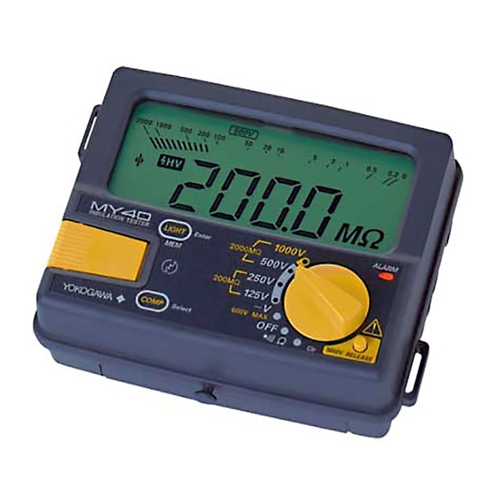
Components
3. LIGHT
key
2. MEAS
key
5. COMPARATOR
key
Side view
1.
Display window (LCD)
Displays the measured values and the function marks
(see section 9, "Display Functions": IM MY40-02EN).
2.
MEAS key
Used for measuring the insulation resistance only.
3.
LIGHT key
Used for turning on/off the backlight.
(MEM key)
Also used for setting memory.
(Enter key)
Also used for confirmation for the comparator and memory functions.
4.
Protective cover fitting
5.
COMP key:
Used for setting the comparator.
(Select key)
Also used for selection for the comparator andmemory functions.
6.
ALARM LED
Flashes for the live-line alarm, and is lit as a warning for the high-voltage alarm.
7.
Function switch
A rotary switch for setting measurement ratings with the following positions:
● 1000 V/2000 MΩ
● 500 V/2000 MΩ
● 250 V/200 MΩ
● 125 V/200 MΩ
● AC voltage measurement
● Power off
● Conductor resistance measurement
8.
1000-V
Turn the function switch to the 1000 V rating position while pressing this button.
RELEASE button
9.
Battery cover setscrew
Undo to replace batteries.
10. Battery cover
11. Shoulder strap guide
The shoulder strap is passed through it.
12. Earth terminal
Connection for earth probe.
13. Line terminal
Connection for line probe.
NOTE
GUARD function is not a standard function.
Without cap: 600 V CAT II
Remarks
Circuits not connected to
a mains power source.
Appliances,
portable equipment, etc.
Distribution board,
circuit breaker, etc.
Overhead wire,
cable systems, etc.
Front view
1. Display window
(LCD)
6. ALARM LED
ALARM
1000V
INSULATION
LIGHT
Enter
TESTER
2000M
500V
7. Function
MEM
250V
MEAS
200M
selector switch
PULL LOCK
125V
V
600V MAX
OFF
COMP
Select
1000V RELEASE
Clr
8. 1000-V RELEASE button
for setting 1000-V rating
4. Protective cover
fitting
Rear view
12. Earth
terminal
13. Line
terminal
OPEN
9. Battery cover
10. Battery cover
setscrew
Insulation resistance
measurement
(maximum input voltage: 600 V)
Continuity test
Clr: Memory clea
11. Shoulder strap
guide
Advertisement

Related Manuals for YOKOGAWA MY40


Summary of Contents for YOKOGAWA MY40
- Page 1 Use the line probe with the cap on for safety (safety standard: EN61010-031). Before using this product, thoroughly read this manual to understand how to use it properly. The following manuals, including this one, are provided as manuals for the MY40. Please read all manuals. IM MY40-E: Safety precautions, components and specifications etc.
- Page 2 5550 V AC and 50/60 Hz for 1 minute Yokogawa Europe B.V. is the authorized representative of Yokogawa Meters & Instruments Corporation for Effect of vibration There is no structural damage and When a vibration frequency of 25 Hz and a peak-to-peak this product in the EEA.
Need help?
Do you have a question about the MY40 and is the answer not in the manual?
Questions and answers