
Related Manuals for ASD FieldSpec 3


Summary of Contents for ASD FieldSpec 3
- Page 1 FieldSpec® 3 User Manual ASD Document 600540 Rev. J © 2010 by ASD Inc. www.asdi.com...
-
Page 2: Trademark Information
HandHeld2™ are registered, and unregistered trademarks, and the intellectual property of Analytical Spectral Devices, Inc. (dba ASD Inc.). All trademarks used or displayed in this material are the property of ASD, its affiliates, or third party owners. Unauthorized use of these trademarks is illegal and punishable by law. -
Page 3: Table Of Contents
Maintenance......... . . 28 Returning Instrument to ASD for Service . - Page 4 ......77 Wireless Interface is Disabled in the Netcfg Application ....77 ASD Document 600540 Rev. J FieldSpec® 3 User Manual...
- Page 5 ....... . 79 What are the differences between the ASD spectrometers? .
- Page 6 ............97 ASD Document 600540 Rev. J...
- Page 7 ASD Document 600540 Rev. J FieldSpec® 3 User Manual...
- Page 8 Usual precautions are recommended to be taken at all times, either written or otherwise, to avoid personal injury or damage to ASD equipment. ASD Document 600540 Rev. J viii FieldSpec® 3 User Manual...
- Page 9 7. Do not operate where aerosol (spray) products are being used or where oxygen is being administered. 8. The power supply should be used near to a convenient and easily accessible mains socket. ASD Document 600540 Rev. J FieldSpec® 3 User Manual...
- Page 10 Notes: ASD Document 600540 Rev. J FieldSpec® 3 User Manual...
-
Page 11: Chapter 1 Introduction
Fiberoptic cable is fixed. Note: The Fiberoptic cable significantly affects the factory calibration required to measure radiance. Many of the other ASD spectrometers can detach and even interchange Fiberoptic cables, which can affect the accuracy of such calibrated radiance measurements. -
Page 12: Hardware Specifications
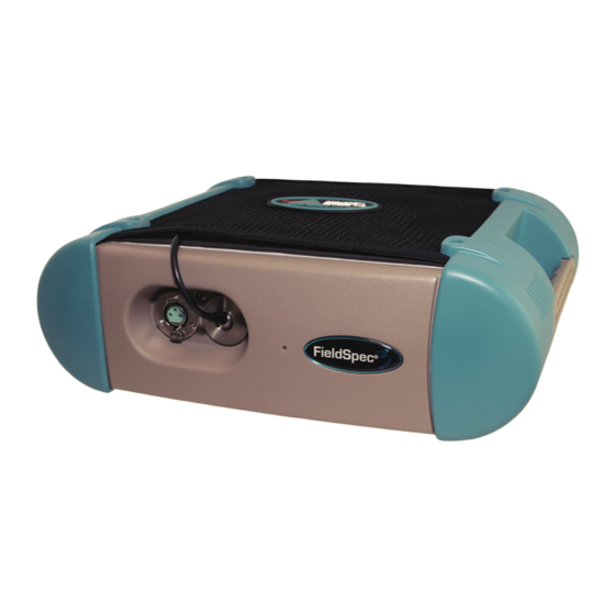
• Durable satin powder coat finish with teal urethane end-caps and handles • All vital components are in a dust-proof enclosure and EMI sealed • Fiberoptic inputs directly to each spectrometer ASD Document 600540 Rev. J FieldSpec® 3 User Manual... -
Page 13: Power Input And Output
350 - 1800 nm SWIR1 only 1000 - 1800 nm SWIR1-SWIR2 1000 - 2500 nm SWIR2 only 1800 - 2500 nm VNIR & SWIR2 350 - 1050 nm and 1800 - 2500 nm ASD Document 600540 Rev. J FieldSpec® 3 User Manual... -
Page 14: Interface Requirement
Note: For information about configuration of the Ethernet card and cable, please refer to the Installation Manual. ASD Document 600540 Rev. J FieldSpec® 3 User Manual... -
Page 15: Standard Accessories
Chapter 1 Introduction 1.1.5 Standard Accessories • FieldSpec® 3 Spectroradiometer • FieldSpec® 3 User Manual (PDF on Flash Drive) • Instrument Controller: ASD-approved laptop computer • Software Pack • 1.5 meter FR Low OH Fiberoptic Cable • Power Supply 12 V •... -
Page 16: Computer Requirements
Regional Settings under Start->Settings->Control Panel. The default language must be set to English (United States) in order for the software to be registered and operate correctly. The numbering format must also be set to English. ASD Document 600540 Rev. J FieldSpec® 3 User Manual... -
Page 17: Theory Of Operation
16-bit analog-to-digital (A/D) converter. This digitized spectral data is then transmitted to the instrument controller for further processing and analysis by the controlling software. ASD Document 600540 Rev. J FieldSpec® 3 User Manual... - Page 18 A full-range FieldSpec spectroradiometer can create packet data sizes over 5 KB. Other single or dual range configurations of the spectroradiometer create smaller data packets (adding the packet sizes as above.) ASD Document 600540 Rev. J FieldSpec® 3 User Manual...
- Page 19 Reflectance is the ratio of energy reflected from a sample to the energy incident on the sample. Spectral Reflectance is the reflectance as a function of wavelength. ASD Document 600540 Rev. J FieldSpec® 3 User Manual...
- Page 20 Absolute reflectance is computed by multiplying the relative reflectance by the known reflectance of the white reference panel. With the reflectance of the reference standard available and known, the ASD or Indico applications can compute the absolute reflectance or transmittance for the material being sampled.
-
Page 21: Chapter 2 Setup
Unpacking the Instrument Step 1 Carefully remove the instrument from its shipping case. Use the nylon straps at the top of the Ergonomic Pro-Pack and the hip belt at the bottom. © 2010 ASD Inc. FieldSpec® 3 User Manual... - Page 22 The spectroradiometer being removed from the carrying case. Figure 2-3 Placement of the Ergonomic Pro-Pack. Step 2 Place the Ergonomic Pro-Pack on a flat surface with the shoulder straps towards the floor. ASD Document 600540 Rev. J FieldSpec® 3 User Manual...
- Page 23 Remove the instrument controller from its compartment on the outside of the Ergonomic Pro-Pack. Figure 2-5 Removing the FieldSpec spectroradiometer from the Ergonomic Pro-Pack. Step 4 Undo the five (5) plastic connectors that hold the FieldSpec spectroradiometer in the Ergonomic Pro-Pack. ASD Document 600540 Rev. J FieldSpec® 3 User Manual...
-
Page 24: Power Supply
• An external adapter for vehicle cigarette lighters (sold separately and should not be used with vehicle engine running). Use only ASD approved power supplies or connectors to power the instrument. ASD Document 600540 Rev. J FieldSpec® 3 User Manual... - Page 25 Insert power (battery or power supply) into the receptacle on the back panel labeled “INPUT 12 VDC 60 WATT”. Lock the connector in place by twisting the barrel end of the connector clockwise. ASD Document 600540 Rev. J FieldSpec® 3 User Manual...
-
Page 26: Ethernet Cables
Ethernet ports of the FieldSpec spectroradiometer and your instrument controller. Figure 2-10 shows the back panel containing the Ethernet port, which is labeled “RJ45/ETHERNET”. Figure 2-11 Shielded cross-over Ethernet cable. ASD Document 600540 Rev. J FieldSpec® 3 User Manual... -
Page 27: Accessory Power Port
Figure 2-12 Enhanced view of the front panel with the Fiberoptic cable connector, port for remote trigger, and accessory power port for probe. The accessory power port is provided for optional ASD approved accessories. Attach the large connector end of the cable into the accessory power port of the front panel. -
Page 28: Pistol Grip
Figure 2-14. The pistol grip has a 25 degree field-of-view, full conical angle. Figure 2-14 Pistol grip components Components of the pistol grip (from left) (1) modified ASD pistol grip, (2) grey nut and (3) strain relief. Figure 2-15 Using the fiberoptic cable with the pistol grip. - Page 29 Chapter 2 Setup The fiberoptic cable (1) feeds into the rear of the pistol grip (2). The strain relief and nut are installed at ASD. Note: If the grey nut and strain relief get separated, the smooth side of the grey nut is inserted into the pistol grip and the rough edge of the grey nut is inserted into the strain relief.
- Page 30 Under the plastic cap at the base of the pistol grip there is a factory adjusted set screw, do not attempt to adjust this set screw. The red-dot scope (sold separately) has a battery compartment is on the top of the pistol grip. ASD Document 600540 Rev. J FieldSpec® 3 User Manual...
-
Page 31: External Trigger
Figure 2-19 shows the trigger switch with its LEDs. The trigger plugs into the spectroradiometer near the Fiberoptic cable, as shown in Figure 2-20. Figure 2-19 External trigger ASD Document 600540 Rev. J FieldSpec® 3 User Manual... - Page 32 The trigger and the Pistol Grip. Note: Accessories such as the pistol grip should have pieces of mesh velcro placed on both sides so that the trigger can be used right- or left-handed. ASD Document 600540 Rev. J FieldSpec® 3 User Manual...
-
Page 33: Laptop Carrier (Belly Board)
Adjust the shoulder straps of the Ergonomic Pro-Pack for comfort. Step 4 Detach the laptop carrier from the neck strap and attach it to the shoulder straps of the Ergonomic Pro-Pack, as shown in Figure 2-22. ASD Document 600540 Rev. J FieldSpec® 3 User Manual... - Page 34 Repeat Step 9 through Step 11 with the other velcro strip but place it a couple of inches or so away from the other strip. This is shown in Figure 2-23. ASD Document 600540 Rev. J FieldSpec® 3 User Manual...
- Page 35 The pistol grip holder can be unscrewed and moved to the left-hand side of the laptop carrier, if necessary. It is recommended that the pistol grip holder is removed when storing the laptop carrier in the shipping trunk. ASD Document 600540 Rev. J FieldSpec® 3 User Manual...
- Page 36 Chapter 2 Setup Figure 2-24 Placing the pistol grip onto the pistol grip holder. Figure 2-25 The laptop carrier with instrument controller and neck strap. ASD Document 600540 Rev. J FieldSpec® 3 User Manual...
-
Page 37: Chapter 3 Usage And Maintenance
All operators should be familiar with this information. Light Sources Use only light sources supplied by ASD Inc. Light sources supplied by ASD are designed to provide levels of illumination and stability of output that complement the performance of ASD instrumentation. -
Page 38: Cleaning
Returning Instrument to ASD for Service In order to return the instrument to ASD for maintenance or repair, a Return Merchandise Authorization (RMA) must be issued by ASD technical support. The RMA includes scheduling details, contact information, shipping instructions, as well as a brief description of the maintenance or repair requirements. -
Page 39: Chapter 4 Fiberoptic Interface
Chapter 4 Fiberoptic Interface ASD offers a variety of fiberoptic cable lengths to interface with the FieldSpec spectroradiometer. These fiberoptic cables are used for reflectance, transmittance, radiance, or irradiance measurements. The fiberoptic cable is routed straight through the front panel to the spectrometer. -
Page 40: Led Check For Fiberoptic Cable
Fiber Check utility. Step 1 Remove any fore optic accessories from the spectrometer’s Fiberoptic cable. Step 2 Attach the magnifier to the end of the Fiberoptic cable, as shown in Figure 4-1. ASD Document 600540 Rev. J FieldSpec® 3 User Manual... - Page 41 Chapter 4 Fiberoptic Interface Figure 4-1 Magnifier for testing the Fiberoptic cable. Step 3 On the instrument controller, exit any ASD applications that might be running and communicating with the unit. Such applications include RS and Indico. Step 4 Ensure that the spectrometer is turned on.
- Page 42 GREEN for SWIR2. • The fiber bundle for each range contains 19 fibers. • Each broken fiber results in a 5.26% loss of response in that particular range (VNIR, SWIR1, or SWIR2). ASD Document 600540 Rev. J FieldSpec® 3 User Manual...
-
Page 43: Fore Optic Discussion
The instrument can be successfully used with a few broken fibers in each range, although with a reduction in signal strength. For severely damaged Fiberoptic cables, send the instrument back to ASD Inc. in the carrying case for repairs. Fore Optic Discussion The Fiberoptic cable provides the flexibility to adapt the instrument to a wide range of applications. - Page 44 Y = D + 2 * X * Tan( A/2 ) Far Field (greater than 1 meter): Y = 2 * X * Tan( A/2 ) Table 4-1 Values of D in mm for ASD Foreoptics VNIR 1° 44.1 17.7 2°...
- Page 45 Chapter 4 Fiberoptic Interface Irradiance Observations ASD has several types of foreoptics for irradiance measurements. These include: • In-air cosine corrected receptors for measurement of total irradiance • Accessories for measurement of direct irradiance • Under-water cosine corrected receptors for measurement of in-water up- and down-welling irradiance.
- Page 46 Chapter 4 Fiberoptic Interface Notes: ASD Document 600540 Rev. J FieldSpec® 3 User Manual...
-
Page 47: Chapter 5 Batteries
When you receive a new battery pack, charge it fully before using it the first time regardless of it showing full voltage and power. It can take from three (3) to five (5) charge-and-discharge cycles before the battery pack reaches its peak performance. © 2010 ASD Inc. FieldSpec® 3 User Manual... -
Page 48: Battery Charger
Whether discharged or not, the NiMH batteries should be charged at least every sixty (60) days. WARNING! Do not use batteries other than those supplied by ASD. Do not use ASD batteries in a manner unauthorized by ASD. Using improper batteries or improper use of ASD batteries could result in bodily injury or damage to the instrument. -
Page 49: Application Battery Indicator
Application Battery Indicator The RS and Indico applications from ASD have a Power Status. It is located at the bottom of the main window next to the Connection Status.The voltage level of the spectrometer will be reported in the balloon type window. - Page 50 Chapter 5 Batteries Notes: ASD Document 600540 Rev. J FieldSpec® 3 User Manual...
-
Page 51: Transporting And Carrying The Fieldspec
Therefore, the first steps required for preparing the FieldSpec spectroradiometer for transport with the shipping case involve putting the spectroradiometer into the Ergonomic Pro-Pack. © 2010 ASD Inc. FieldSpec® 3 User Manual... - Page 52 When facing the outside of the pack, we recommend putting the Fiberoptic cable on the left (as shown in Figure 6-1), this puts the cable on top when placed into the shipping case. ASD Document 600540 Rev. J FieldSpec® 3 User Manual...
-
Page 53: Chapter 6 Transporting And Carrying The Fieldspec® 3
Two straps are on each side and one at the top. Figure 6-3 Ergonomic Pro-Pack with the instrument controller. Step 4 Place the instrument controller into its compartment of the Ergonomic Pro-Pack and zip up the zippers. ASD Document 600540 Rev. J FieldSpec® 3 User Manual... - Page 54 Chapter 6 Transporting and Carrying the FieldSpec® 3 Figure 6-4 Folding the left battery pouches into the Ergonomic Pro-Pack. Figure 6-5 Folding the right battery pouches into the Ergonomic Pro-Pack. ASD Document 600540 Rev. J FieldSpec® 3 User Manual...
- Page 55 Ergonomic Pro-Pack with the Fiberoptic cable on either side. We recommend following these instructions which puts the Fiberoptic cable on top when placed in the case. ASD Document 600540 Rev. J FieldSpec® 3 User Manual...
-
Page 56: Preparing The Fieldspec® 3 And Ergonomic Pro-Pack For The Field
Follow the instructions for unpacking the FieldSpec spectroradiometer and Ergonomic Pro-Pack from the shipping case. Step 2 Place the Ergonomic Pro-Pack on a flat surface with the shoulder straps towards the floor. ASD Document 600540 Rev. J FieldSpec® 3 User Manual... - Page 57 The Fiberoptic spool is optional and may not even be needed for short cables. The battery pouches on the hip belt have velcro loops for holding the cable, as is shown in Figure 6-11. ASD Document 600540 Rev. J FieldSpec® 3 User Manual...
- Page 58 Figure 6-9 Fiberoptic spool on the outside of the Ergonomic Pro-Pack (with velcro). Figure 6-10 Fiberoptic spool and where it attaches with snaps to the battery pouch on the hip belt. ASD Document 600540 Rev. J FieldSpec® 3 User Manual...
- Page 59 Feed the battery cable up from the battery pouch under the cross strap to the power input of the FieldSpec spectroradiometer, as shown in Figure 6-12. Figure 6-12 Routing the battery cable to the FieldSpec spectroradiometer. ASD Document 600540 Rev. J FieldSpec® 3 User Manual...
- Page 60 Chapter 6 Transporting and Carrying the FieldSpec® 3 Figure 6-13 Fiberoptic cable spool on the outside of the Ergonomic Pro-Pack. Figure 6-14 Fiberoptic cable spool on the battery pouch on the hip belt. ASD Document 600540 Rev. J FieldSpec® 3 User Manual...
- Page 61 Ergonomic Pro-Pack. Step 12 Place the instrument controller onto the velcro of the laptop carrier. Step 13 The laptop carrier is equipped with a pistol grip holder. Figure 6-16 Pistol grip holder. ASD Document 600540 Rev. J FieldSpec® 3 User Manual...
-
Page 62: Carrying Supplies
FieldSpec spectroradiometer. The straps on the outside of the pack are intended for tying on clothing or other large items. ASD Document 600540 Rev. J FieldSpec® 3 User Manual... -
Page 63: Protecting The Instrument In The Field
The shoulder straps are still free allowing you to hike towards shelter. Figure 6-19 Rain flap storage in the Ergonomic Pro-Pack. ASD Document 600540 Rev. J FieldSpec® 3 User Manual... - Page 64 Rain flap covering the unit. WARNING! Do not attempt to use the spectroradiometer with the rain flap deployed. The spectroradiometer may overheat, because the rain flap prevents adequate air from circulating to the instrument. ASD Document 600540 Rev. J FieldSpec® 3 User Manual...
-
Page 65: Chapter 7 Field Measurements
• Spatial and temporal variability of the sample characteristics. Many of these parameters are controlled when using one of ASD’s standard sampling interfaces (e.g., MugLite or Contact Probe). Spectral field measurements are desirable for many reasons, not all related to remote sensing. -
Page 66: Illumination
(see Figure 7-1), each with its own spectral characteristics. Unless the target is in a shadow, the direct solar illumination is the dominant source of illumination. ASD Document 600540 Rev. J FieldSpec® 3 User Manual... - Page 67 When compared to a smooth surface, a surface with a rough texture will tend to have a higher portion of illumination from the diffuse and scattered-from-surroundings sources relative to the direct solar illumination. ASD Document 600540 Rev. J FieldSpec® 3 User Manual...
-
Page 68: Characteristics Of Artificial Illumination
By far, water vapor is the strongest modifier of the incoming solar spectrum. Water vapor has absorption features spanning the solar reflected region of the spectrum (see Figure 7-2), and varies both spatially and temporally. ASD Document 600540 Rev. J FieldSpec® 3 User Manual... - Page 69 Figure 7-3 Transmission spectrum of carbon dioxide for typical atmospheric conditions. Other major atmospheric components that influence the atmospheric transmission spectrum are shown in Figure 7-4. ASD Document 600540 Rev. J FieldSpec® 3 User Manual...
-
Page 70: Clouds
While they are difficult to see and often appear inconsequential, the presence of cirrus clouds tends to educe significant variability in atmospheric water vapor. ASD Document 600540 Rev. J FieldSpec® 3 User Manual... -
Page 71: Wind
Because of the complex three dimensional geometry of a plant canopy, light returned from the canopy is a complex mixture of multiply reflected and/or transmitted components. The canopy level optical signal is dependant upon: • Illumination and viewing geometry. • Canopy structure. ASD Document 600540 Rev. J FieldSpec® 3 User Manual... - Page 72 • plant pigments » chlorophyll » zanthophyll » carotenoids Other, minor, absorption features are attributable to other chemical components; these include: • cellulose • lignin • proteins • starches • sugars ASD Document 600540 Rev. J FieldSpec® 3 User Manual...
- Page 73 Table 7-1. Table 7-1 Major variables affecting the Bidirectional Reflectance Distribution Function (BRDF) of a vegetated canopy Illumination • Geometry » angle-of-incidence of Sun (or Radar) » azimuth • Spectral characteristics ASD Document 600540 Rev. J FieldSpec® 3 User Manual...
-
Page 74: Rocks, Soils, And Man-Made Materials
The overall brightness of the observed spectrum does change with illumination and viewing geometry due to changes in the amount of shadow in the field-of-view of the spectrometer. ASD Document 600540 Rev. J FieldSpec® 3 User Manual... -
Page 75: Experimental Design
If the purpose of a study is to understand how a process effects the spectral signature of a target without consideration of how background materials and other sources of variability affect the spectral signature, variance from sources ASD Document 600540 Rev. J FieldSpec® 3 User Manual... -
Page 76: Viewing Geometry
Step 5 Optimize the instrument to the Spectralon. ASD Document 600540 Rev. J FieldSpec® 3 User Manual... -
Page 77: Indico Application
When optimization and white reference are complete, you should see a straight baseline across the Project Graph at 1.00 (100%). Step 9 Select the Display->Reflectance [Alt+D, R] for the reflectance mode. ASD Document 600540 Rev. J FieldSpec® 3 User Manual... - Page 78 When the FieldSpec spectroradiometer finishes recording and averaging the Spectra, the graph in the project window will be updated to show the reflectance spectrum of the sample. Step 12 Observe samples. Figure 7-5 Solar illumination factors ASD Document 600540 Rev. J FieldSpec® 3 User Manual...
-
Page 79: White Reference
FieldSpec spectroradiometer using the white reference as the standard. Spectralon from Labsphere is the white reference standard that is very suitable for the VNIR and SWIR spectral ranges of ASD instruments. Spectralon is made of polytetraflouroethylene (PTFE) and cintered halon. It has the characteristic of being nearly 100% reflective within the wavelength range of 350 nm to 2500 nm. -
Page 80: Maintaining Spectralon References
(water beads and runs off immediately). Step 1 Use a flat surface, such as a thick, flat piece of glass. ASD Document 600540 Rev. J FieldSpec® 3 User Manual... -
Page 81: White Reference Procedures
Any atmospheric changes. • Temperature changes. • Whenever accessory probes are changed. Note: Environmental conditions can change rapidly or slowly. It all depends on clouds, wind (affecting temperature), instrument warm up time, etc. ASD Document 600540 Rev. J FieldSpec® 3 User Manual... - Page 82 Chapter 7 Field Measurements Notes: ASD Document 600540 Rev. J FieldSpec® 3 User Manual...
-
Page 83: Appendix A Troubleshooting
The FieldSpec spectroradiometer uses industry standard components. You should see the same general connection speed and distance capabilities as other wireless devices. Does Not Connect to the Spectrometer • Refer to section A.1, Common Communication Fixes. © 2010 ASD Inc. FieldSpec® 3 User Manual... - Page 84 For an established network, check that the Ethernet cable is a standard Ethernet cable. • Check that the IP Address is in the same range or subnet as the ASD spectrometer. The same subnet means that the first three octets of the IP address (xxx.xxx.xxx.___) match the spectrometer and the computer.
-
Page 85: Does Not Connect Wireless
Refer to section A.1, Common Communication Fixes. • Check to make sure the wireless adapter is in the same range as the ASD spectrometer. The default IP Address for the ASD spectrometer is: 10.1.1.11 for the Ethernet interface, or »... - Page 86 » Right click on the wireless adapter. » Select View Available Wireless Networks. » Make sure the ASD spectrometer shows up in the list of wireless networks. If the spectrometer is not connected, » Select the spectrometer. » Select the Connect button.
-
Page 87: Does Not Connect To The Access Point
If you are using encryption, then make sure you are using the same WEP key in the spectrometer as the access point. • Move the access point, spectrometer, and instrument controller (computer) to the same room to test the connection. ASD Document 600540 Rev. J FieldSpec® 3 User Manual... -
Page 88: Spectrometer Loses Its Wireless Connection
Common Communication Fixes. • Check to make sure the wireless adapter is in the same range as the spectrometer. The default IP Address for the ASD spectrometer is: 10.1.1.11 for the Ethernet interface, or » 10.1.1.77 for the wireless interface. »... - Page 89 Appendix A Troubleshooting Notes: ASD Document 600540 Rev. J FieldSpec® 3 User Manual...
- Page 90 Appendix A Troubleshooting ASD Document 600540 Rev. J FieldSpec® 3 User Manual...
-
Page 91: Appendix B Reference Information
Spectrograph - An optical instrument for forming the spectrum of a light source and recording it on a film. The dispersing medium may be a prism or a diffraction grating. This term was common prior to the digital age. ASD instruments do not use film. -
Page 92: What Are The Differences Between The Asd Spectrometers
Remote sensing is defined as the art and science of obtaining information about an object without being in direct physical contact with the object. The ASD spectrometers achieve this using visible near-infrared (VNIR) and short-wave infrared (SWIR) spectra. ASD Document 600540 Rev. J... -
Page 93: How Often Do I Need To Optimize
60 scans for the white reference. The white reference isn’t taken as often, which is why you would want to include more scans in its averaging. ASD Document 600540 Rev. J FieldSpec® 3 User Manual... -
Page 94: What If I Want To Keep The Same Settings All Day
The field-of-view is labeled on the foreoptic that you use. The bare fiber has a 25 degree field-of-view. When you are measuring radiance, it is important that the RS application software is using the correct field-of-view setting. ASD Document 600540 Rev. J FieldSpec® 3 User Manual... -
Page 95: B.1.10 What Are The Units Of Radiance
Reflectance and transmission measurements are ratios of the optical energy from a sample compared to the optical energy from a reference panel. The units cancel out, so these measurements do not use the calibration files to calculate radiance. ASD Document 600540 Rev. J FieldSpec® 3 User Manual... -
Page 96: B.1.11 Can I Post-Process My Data
Various software packages are available for chemometric model. The spectral data can be imported into many different applications. The complete specification of the ASD file format is available upon request. B.1.12 Why do I see oscillations (sine wave) in my data? Your light source may use AC power. -
Page 97: What Are These Upward Or Downward Spikes In Vnir Data
FOV of the individual strands to overlap and mesh together. Stepping of data is common when the foreoptic has a lens, and less common when using the bare optics or sampling devices. ASD Document 600540 Rev. J FieldSpec® 3 User Manual... -
Page 98: B.1.16 What Can Cause More Noise In My Data From Last Time
B.1.19 How do I set up GPS? The GPS feature is enabled in the RS application software. To configure the GPS: Step 1 Select either: ASD Document 600540 Rev. J FieldSpec® 3 User Manual... -
Page 99: B.1.20 What Does A Broken Fiber Mean
Therefore, a single broken fiber results in a ~5% reduction in the signal in a given region. Therefore, a single broken fiber in the internal cable results in a ~5% reduction in the signal in a given region. ASD Document 600540 Rev. J FieldSpec® 3 User Manual... -
Page 100: B.1.21 How Long Is The Battery Life
30% capacity can result in up to 1,000 uses. Note: The limiting factor for how long you can work in the field may be the battery in the instrument controller rather than the spectroradiometer’s batteries. ASD Document 600540 Rev. J FieldSpec® 3 User Manual... -
Page 101: What Type Of Ethernet Cable Can I Use For The Static Ip Configuration
Programs running in the background can cause packets to be lost. Microsoft Office, image processing programs, and other software applications generally do not interfere with ASD programs, particularly if they are not running and competing for CPU cycles and RAM at the same time that data is being collected from the FieldSpec spectroradiometer. -
Page 102: How Long Does It Take For The Fieldspec Spectroradiometer To Warm Up
Gains and offsets are determined during optimization by an optimization algorithm in the RS application. You can observe this process in the RS application by depressing the OP button on the top right-hand toolbar. The ASD Document 600540 Rev. J FieldSpec® 3 User Manual... -
Page 103: Light Source
(increases with ambient temperature). Light Source When using ASD's ProLamp illumination source, the less intense the lamp setting (knob on side of light source), the more diffuse (homogeneous) it will be. An average spot size of reasonable homogeneity is about 10 cm at a 50 cm lamp distance. -
Page 104: Spectral Discontinuities
The steps result from the different spectrometers viewing slightly different areas on the sample. The steps are seen when these three areas (VNIR, SWIR1 & SWIR2) have ASD Document 600540 Rev. J FieldSpec® 3 User Manual... -
Page 105: White Reference
The drawback to this is that the resultant data can be compromised by introducing low-frequency noise factors, such as varying cloud conditions or sudden gusts of wind changing the color of the tree canopy. ASD Document 600540 Rev. J FieldSpec® 3 User Manual... -
Page 106: Temperature Effects
The ASD applications provide a warning when the SWIR detectors are out of thermal regulation. Technical Support If you have any questions or concerns, please contact ASD Inc. by phone, fax, or email: Phone: 303-444-6522 X-144 Fax: 303-444-6825... -
Page 107: W.e.e.e. Compliance
August 13, 2005. If you decide to end the use of the spectrometer, please do not discard it as general waste. ASD will accept the return of your instrument for recycling purposes. Contact ASD Customer Service to arrange for return of your instrument. - Page 108 Appendix B Reference Information Notes: ASD Document 600540 Rev. J FieldSpec® 3 User Manual...
-
Page 109: Index
Windows LED fiberoptic check dark current in VNIR light source Dark Current measurement light sources data conversion data sinusoidal wave discontinuities maintenance annual materials edge effects man-made Ergonomic Pro-Pack belly board © 2010 ASD Inc. FieldSpec® 3 User Manual... - Page 110 ASD Document 600540 Rev. J FieldSpec® 3 User Manual...
Need help?
Do you have a question about the FieldSpec 3 and is the answer not in the manual?
Questions and answers