
Subscribe to Our Youtube Channel
Related Manuals for Chameleon Antenna CHA TD 2.0


Summary of Contents for Chameleon Antenna CHA TD 2.0
- Page 1 Terminated Dipole 2.0 (CHA TD 2.0) Operator’s Manual Nevada - USA WWW.CHAMELEONANTENNA.COM VERSATILE – DEPENDABLE – STEALTH – BUILT TO LAST...
-
Page 2: Table Of Contents
10 watts or above 14 MHz. Never use this antenna near RF sensitive medical devices, such as pacemakers. All information on this product and the product itself is the property of and is proprietary to Chameleon Antenna . Specifications are subject to change without prior notice. CHA TD 2.0 Page 2... -
Page 3: Introduction
Automatic Link Establishment (ALE), frequency-hopping, and spread-spectrum modes without a tuner or coupler. The CHA TD 2.0 can be deployed by the operator in the field in less than 15 minutes, using almost any available support, with no masts or guying required. -
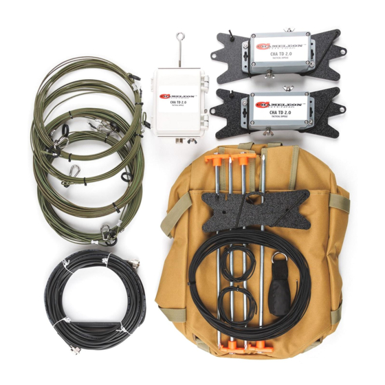
Page 4: Parts Of The Antenna
The CHA TD 2.0 is comprised of the following components: a. Matching Transformer The Matching Transformer, see plate (2), provides impedance matching for the CHA TD 2.0. It is permanently affixed to the Center Line Winder (b). b. Center Line Winder CHA TD 2.0... - Page 5 The Center Line Winder is used to store the Paracord (n) and enables rapid deployment and recovery of the CHA TD 2.0. The Matching Transformer (a) is permanently affixed to the Center Line Winder. The Center Line Winder is also used as the center or end support for the erected antenna.
- Page 6 Paracord, 550 Paracord (not pictured) is used to suspend components of the CHA TD 2.0 at the proper height or anchor them to the ground, depending upon the antenna configuration. Additional 50 foot length of Paracord on a Line Winder are available for purchase from Chameleon Antenna .
-
Page 7: Antenna Configurations
Field Pouch The Field Pouch, see plate (1), is used to store the components of the CHA TD 2.0, enabling rapid deployment and recovery, and making the antenna portable and man-packable. p. Coaxial Cable Assembly The Coaxial Cable Assembly (not pictured, not supplied) connects to the UHF Socket (e) at one end and the Radio Set at the other. -
Page 8: Terminated Horizontal Dipole
Terminating the Horizontal Dipole makes the antenna broad-banded. The Horizontal Dipole requires at least two supports (one at each end). A center support is also recommended. The CHA TD 2.0 Terminated Horizontal Dipole should be mounted at a height of around 25 to 40 feet for good overall results. When mounted at this height, the antenna is omnidirectional at lower frequencies. -
Page 9: Terminated Inverted "V
Inverted “V” is the ease of installation; in that it requires only one support and takes less space than a horizontal dipole antenna. The CHA TD 2.0 Terminated Inverted “V” should be mounted at a height of around 25 to 40 feet for good overall results. - Page 10 Figure 2. Terminated Inverted “V” Configuration. Site Selection and Preparation. 8. Connect the Wire Connector from the other 1. Select a site to deploy the CHA TD 2.0 Terminated Antenna Wire to the Antenna Connection (c). Inverted “V” configuration, see figure (2). The This is the red wing nut.
-
Page 11: Terminated "M
Service band enabling medium to long range skywave propagation for communications outside the affected region. The CHA TD 2.0 Terminated “M” should be mounted at a height of around 25 to 40 feet for good overall results. When mounted at this height, the antenna is predominantly bidirectional broadside to the antenna. -
Page 12: Terminated Sloping Wire
16. Perform operational test. Terminated Sloping Wire The CHA TD 2.0 Sloping Wire configuration, see figure (5), is a broadband medium range HF antenna. It should provide acceptable ground wave and sky wave propagation. The Sloping Wire requires one support, is a good general-purpose antenna, and is excellent for hasty deployment. - Page 13 Table 3. Recommended Counterpoise Length. Site Selection and Preparation. This is the red wing nut. Tighten the wing nut 1. Select a site to deploy the CHA TD 2.0 Terminated finger tight. Sloping Wire configuration, see figure (4). The 7. Attach a Carabiner to the Isolation Loop on the best site should have a tree or other support that Antenna Wire.
-
Page 14: Recovery Procedure
TD 2.0 configurations that require more than one support. • Coaxial Cable Assembly. 50 feet of RG-58 with integrated RFI Choke. Used to connect the CHA TD 2.0 to the radio set. This is a highly recommended accessory if you are not using a CHA RFI CHOKE. -
Page 15: Specifications
15 degrees • Personnel Requirements and Setup Time: one trained operator, less than 15 minutes • Far Field plots for the four basic CHA TD 2.0 are shown in figures (5) through (8) Inverted “V” Sloping Wire FREQUENCY 10.1... - Page 16 Figure 5. Terminated Dipole Far Field Plot. Figure 6. Terminated Inverted “V” Far Field Plot. CHA TD 2.0 Page 16...
- Page 17 Figure 7. Terminated “M” Far Field Plot. Figure 8. Terminated Sloping Wire Far Field Plot. CHA TD 2.0 Page 17...
- Page 18 Chameleon Antenna Products The following products are available for purchase at Chameleon Antenna Go to http://chameleonantenna.com for ordering and more information. CHA P-LOOP 2.0 - The CHA P-LOOP 2.0 was designed CHA EMCOMM III Base - The CHA EMCOMM II Base...
-
Page 19: Chameleon Antenna Tm Products
2. 1987, Tactical Single-Channel Radio Communications Techniques (FM 24-18), Department of the Army, Washington, DC. 3. Turkes, Gurkan, 1990, Tactical HF Field Expedient Antenna Performance Volume I Thesis, U.S. Naval Post Graduate School, Monterey, CA. CHA TD 2.0 Page 19...
Need help?
Do you have a question about the CHA TD 2.0 and is the answer not in the manual?
Questions and answers