
Related Manuals for Chameleon Antenna Tactical Dipole 2.0


Summary of Contents for Chameleon Antenna Tactical Dipole 2.0
- Page 1 Tactical Dipole 2.0 (CHA TD 2.0) Operator’s Manual Nevada - USA WWW.CHAMELEONANTENNA.COM VERSATILE – DEPENDABLE – STEALTH – BUILT TO LAST...
-
Page 2: Table Of Contents
Recovery Procedure .......................... 14 Troubleshooting ..........................15 Field Installation and Repair Kit......................15 Specifications ............................ 15 Chameleon Antenna Products ....................... 20 References ............................21 Be aware of overhead power lines when you are deploying the CHA TD 2.0. You could be electrocuted if the antenna gets near or contacts overhead power lines. -
Page 3: Introduction
Introduction Thank you for purchasing and using the Chameleon Antenna Tactical Dipole 2.0 (CHA TD 2.0) antenna. The CHA TD 2.0, shown in plate (1), is a broadband High Frequency (HF) antenna specially designed for short to long range portable and man-pack HF communication, where portability and rapid deployment are essential. - Page 4 HF radio waves propagate from the transmitting horizon. They are usable, during the day and antenna to the receiving antenna using two under optimal conditions, up to around 90 methods: ground waves and sky waves. Ground miles, see table (1). waves are composed of direct waves and Frequency Distance Frequency...
-
Page 5: Parts Of The Antenna
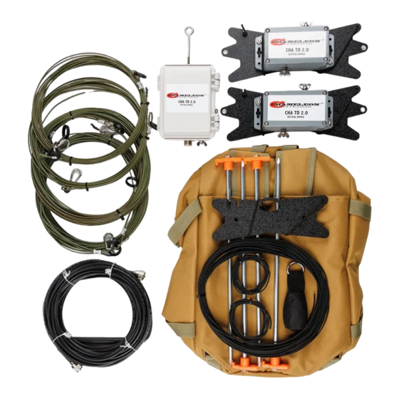
Parts of the Antenna The CHA TD 2.0 is comprised of the components shown in plates (2)-(5). The letter references are used to identify components in the detailed assembly instructions. Plate 2. Matching Transformer Unit Details. A. Matching Transformer Unit E. - Page 6 Plate 3. Antenna and Counterpoise Wire Details. G. Counterpoise Wire (25 ft, Quantity 2) J. Carabiner (Quantity 6) H. Antenna Wire (60 ft, Quantity 2) K. End Loop Terminal Lug L. Insulating Ring Plate 4. Terminating Resistor Unit Details. CHA TD 2.0 Page 6...
- Page 7 M. Terminating Resistor Unit (Quantity 2) Q. Shock Cord N. Resistor Connectors R. Antenna Wire Winding Notch O. Suspension Point S. Counterpoise Wire Winding Notch P. Strain Relief Point Plate 5. Miscellaneous Components Details. T. Tent Stakes (Quantity 4) X. Coaxial Cable U.
-
Page 8: Antenna Assembly
Terminating Resistor Unit Assembly Before first use of the CHA TD 2.0, perform the following procedure to assemble the Terminating Resistor Units, Antenna Wires, and Counterpoise Wires to enable rapid field deployment. Refer to plate (6) for assembly details. is on the same end of the Line Winder as 1. -
Page 9: Antenna Configurations
Antenna Configurations Using the supplied components, the CHA TD 2.0 can be deployed into a number of operationally useful antenna configurations. The two primary antenna configurations described in this manual are the Terminated Inverted “V” and the Terminated Sloping Wire configurations. Note: a floating Insulator Ring is included on both Antenna Wires to enable other antenna configurations that require elevation of the Antenna Wire somewhere along the wire, such as an Inverted “L”... - Page 10 To deploy the Terminated Inverted “V” antenna, perform the following procedure. Site Selection and Preparation. Connection (C). The completed assemblies 1. Perform Terminating Resistor Unit should look like that picture in plate (8). Assembly procedure, if needed. Raise the Antenna 2.
- Page 11 21. Drive the Tent Stakes into the ground at 23. Return unused components to the Duffel that point. Bag and perform an operational test. 22. Rewind Long Mini-Paracord onto Mini-Line Winder (Z). Plate 8. Inverted “V” Antenna Connection Details. CHA TD 2.0 Page 11...
-
Page 12: Terminated Sloping Wire
Terminated Sloping Wire The CHA TD 2.0 Sloping Wire antenna, see figure (2), is a broadband short to medium range HF antenna. It is designed to provide acceptable ground wave and sky wave propagation. This configuration is predominately omnidirectional on lower frequencies, becoming more unidirectional towards the low end of the antenna as the frequency increases. - Page 13 Resistor Unit (M) to be at a height of 13. Untie the Mini-Paracord from the support around 25 feet. If a tall support is and pull the Mini-Terminating Resistor Unit unavailable, any convenient object, such as up to the desired height. a fence post or the top of a vehicle, may be 14.
-
Page 14: Recovery Procedure
24. Connect a UHF Plug (Y) at one end of the 25. Rewind Long Mini-Paracord onto Mini-Line Coaxial Cable (X) to the UHF Socket (F) on Winder (Z). the bottom of the Matching Transformer 26. Return any unused components to the Unit. -
Page 15: Troubleshooting
6. If SWR is greater than 6:1, replace Coaxial Cable assembly. Most problems with antenna systems are caused by the coaxial cables and connectors. 7. If still not operational, contact Chameleon Antenna for technical support. Be sure to provide the specific indications of the problem (e.g., “My antenna tuner can’t find a match when tuning up and I... - Page 16 • Color: Gray/Black. • Personnel Requirements and Setup Time: one trained operator, approximately 10 minutes. • Figures (4) through (10) show Far Field plots for the various CHA TD 2.0 configurations. Figure 3. Measured SWR. Figure 4. Terminated Inverted “V”, 3.7 MHz. CHA TD 2.0 Page 16...
- Page 17 Figure 5. Terminated Inverted “V”, 7.1 MHz. Figure 6. Terminated Inverted “V”, 14.1 MHz. CHA TD 2.0 Page 17...
- Page 18 Figure 7. Terminated Sloping “V” (110° Opening), 14.1 MHz. CHA TD 2.0 Page 18...
- Page 19 Figure 8. Terminated Sloping Wire, 3.7 MHz. Figure 9. Terminated Sloping Wire, 7.1 MHz. CHA TD 2.0 Page 19...
-
Page 20: Chameleon Antenna Tm Products
Figure 10. Terminated Sloping Wire, 14.1 MHz. Chameleon Antenna Products Please go to http://chameleonantenna.com for information about additional quality antenna products available for purchase from Chameleon Antenna – The Portable Antenna Pioneer CHA TD 2.0 Page 20... -
Page 21: References
References 1. Silver, H. Ward (editor), 2013, 2014 ARRL Handbook for Radio Communications, 91 Edition, American Radio Relay League, Newington, CT. 2. 1987, Tactical Single-Channel Radio Communications Techniques (FM 24-18), Department of the Army, Washington, DC. 3. Turkes, Gurkan, 1990, Tactical HF Field Expedient Antenna Performance Volume I Thesis, U.S. Naval Post Graduate School, Monterey, CA.
Need help?
Do you have a question about the Tactical Dipole 2.0 and is the answer not in the manual?
Questions and answers