
Related Manuals for Chameleon Antenna EMCOMM III


Summary of Contents for Chameleon Antenna EMCOMM III
- Page 1 EMCOMM III Portable Antenna Operator’s Manual Nevada - USA WWW.CHAMELEONANTENNA.COM VERSATILE – DEPENDABLE – STEALTH – BUILT TO LAST Updated: January 2020...
-
Page 2: Table Of Contents
10 watts or above 14 MHz. Never use this antenna near RF sensitive medical devices, such as pacemakers. All information on this product and the product itself is the property of and is proprietary to Chameleon Antenna . Specifications are subject to change without prior notice. EMCOMM III Portable Page 2... -
Page 3: Introduction
Portable antenna, see plate (1), is a portable High Frequency (HF) antenna specially designed for short to long range portable and man-pack HF communications. The EMCOMM III Portable antenna is ideal for hiking, backpacking, and both tent and Recreational Vehicle (RV) camping. It is also highly suitable for military, government agencies, non-... -
Page 4: Parts Of The Antenna
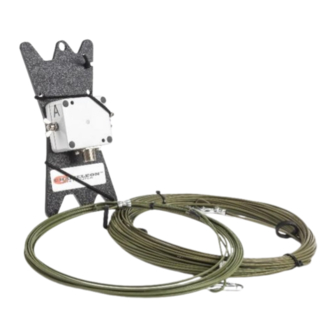
2 to 10 MHz. Frequencies of 2 – 4 MHz are typical at night and 4 – 8 MHz during the day. Parts of the Antenna The EMCOMM III Portable antenna is comprised of the following components, refer to plate (2): EMCOMM III Portable... - Page 5 Matching Transformer The Matching Transformer provides impedance matching for the EMCOMM III Portable antenna. It is permanently affixed to the Line Winder (b). EMCOMM III Portable Page 5...
- Page 6 The Line Winder is used to store the Antenna and Counterpoise Wires and enables rapid deployment and recovery of the EMCOMM III Portable antenna. The Matching Transformer (a) is permanently affixed to the Line Winder. The Line Winder is also used as the end support for the erected antenna.
-
Page 7: Initial Assembly
The Carabiner is used to attach the Antenna Wire and Counterpoise Wires to the Strain Relief Holes (n) in the Line Winder. Paracord, 550 Paracord (not pictured, not supplied) is used to suspend components of the EMCOMM III Portable antenna at the proper height or anchor it to the ground, depending upon the antenna configuration. Coaxial Cable Assembly The Coaxial Cable Assembly (not pictured, not supplied) connects to the UHF Socket (e) at one end and the Radio Set at the other. -
Page 8: Antenna Configurations
Line Winder. Antenna Configurations Using the supplied components, the EMCOMM III Portable antenna can be deployed into a number of useful configurations. Three basic configurations are described in this manual, each with unique performance characteristics. -
Page 9: Inverted "L" / Sloping Wire Configurations
Inverted “L” / Sloping Wire Configurations The EMCOMM III Portable antenna, Inverted “L” and Sloping Wire configurations, see figure (1), are medium to long range HF antennas. They should provide acceptable ground wave and sky wave propagation. The Inverted “L” and Sloping Wire configurations are excellent general-purpose antennas and are a good choice when two supports are available (for the Inverted “L”) or one support (for the Sloping Wire) and there is sufficient time for site selection... -
Page 10: End-Fed Inverted "V
15. Perform operational test. End-Fed Inverted “V” The EMCOMM III Portable antenna End-Fed Inverted “V” configuration, see figure (2), is a medium range HF antenna. The End-Fed Inverted “V” is a good compromise between performance and ease of installation since it requires only one center support, has a reasonably small foot-print, and provides good sky wave propagation. -
Page 11: Horizontal End-Fed (Nvis)
14. Perform operational test. Horizontal End-Fed (NVIS) The EMCOMM III Portable antenna Horizontal End-Fed (NVIS) configuration, see figure (3), is a short to medium range HF antenna. The Horizontal End-Fed configuration will provide good NVIS propagation on lower frequencies and medium range sky wave propagation on upper frequencies. It requires two supports and should be mounted at a height of 25 feet for good overall results. - Page 12 Figure 3. Horizontal NVIS Configuration. Site Selection and Preparation. Raise the antenna. Select a site to deploy the EMCOMM III Portable Using a throw weight or some other method, antenna End-Fed Horizontal (NVIS) loop the free end of the Paracord from the Line configuration, see figure (3).
-
Page 13: Recovery Procedure
Tent Stakes. • Coaxial Cable Assembly. 50 feet of RG-58 with integrated RFI Choke. Used to connect the EMCOMM III Portable to the radio set. This is a highly recommended accessory if you are not using a CHA RFI CHOKE. - Page 14 15 degrees • Personnel Requirements and Setup Time: one trained operator, less than 15 minutes • Far Field plots for the three basic and special EMCOMM III Portable antenna configurations are shown in figures (4) through (7) FREQUENCY 10.1 14.1...
- Page 15 Figure 5. End-Fed Inverted “V” Far Field Plot. Figure 6. Horizontal End-Fed Far Field Plot. EMCOMM III Portable Page 15...
-
Page 16: References
Relay League, Newington, CT. 1987, Tactical Single-Channel Radio Communications Techniques (FM 24-18), Department of the Army, Washington, DC. Turkes, Gurkan, 1990, Tactical HF Field Expedient Antenna Performance Volume I Thesis, U.S. Naval Post Graduate School, Monterey, CA. EMCOMM III Portable Page 16... - Page 17 EMCOMM III Portable Page 17...
Need help?
Do you have a question about the EMCOMM III and is the answer not in the manual?
Questions and answers