
Subscribe to Our Youtube Channel
Related Manuals for Chameleon Antenna EMCOMM III


Summary of Contents for Chameleon Antenna EMCOMM III
- Page 1 EMCOMM III Portable Antenna Operator’s Manual Nevada - USA WWW.CHAMELEONANTENNA.COM VERSATILE – DEPENDABLE – STEALTH – BUILT TO LAST...
-
Page 2: Table Of Contents
10 watts or above 14 MHz. Never use this antenna near RF sensitive medical devices, such as pacemakers. All information on this product and the product itself is the property of and is proprietary to Chameleon Antenna . Specifications are subject to change without prior notice. EMCOMM III Portable Page 2... -
Page 3: Introduction
Portable antenna, see plate (1), is a portable High Frequency (HF) antenna specially designed for short to long range portable and man-pack HF communications. The EMCOMM III Portable antenna is ideal for hiking, backpacking, and both tent and Recreational Vehicle (RV) camping. It is also highly suitable for military, government agencies, non-... -
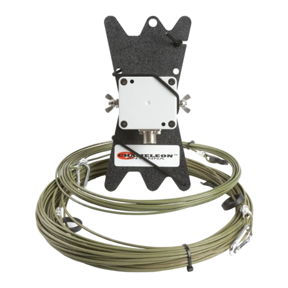
Page 4: Parts Of The Antenna
The EMCOMM III Portable antenna is comprised of the following components: a. Matching Transformer The Matching Transformer, see plate (2), provides impedance matching for the EMCOMM III Portable antenna. It is permanently affixed to the Line Winder (b). b. Line Winder... - Page 5 The Line Winder is used to store the Antenna Wire (g) and enables rapid deployment and recovery of the EMCOMM III Portable antenna. The Matching Transformer (a) is permanently affixed to the Line Winder. The Line Winder is also used as the end support for the erected antenna.
- Page 6 Wire (g). Paracord, 550 Paracord (not pictured) is used to suspend components of the EMCOMM III Portable antenna at the proper height or anchor them to the ground, depending upon the antenna configuration. Additional 50 foot length of Paracord on a Line Winder are available for purchase from Chameleon Antenna .
-
Page 7: Antenna Configurations
Antenna Configurations Using the supplied components, the EMCOMM III Portable antenna can be deployed into a number of useful configurations. Three basic configurations are described in this manual, each with unique performance characteristics. Table (2) shows the antenna configurations described in this manual. The table can assist the operator to quickly select the most appropriate antenna configuration to meet their operational requirements. -
Page 8: Inverted "L" / Sloping Wire Configurations
Inverted “L” / Sloping Wire Configurations The EMCOMM III Portable antenna, Inverted “L” and Sloping Wire configurations, see figure (1), are medium to long range HF antennas. They should provide acceptable ground wave and sky wave propagation. The Inverted “L” and Sloping Wire configurations are excellent general-purpose antennas and are a good choice when two supports are available (for the Inverted “L”) or one support (for the Sloping Wire) and there is sufficient time for site selection... - Page 9 8. Connect the Coaxial Cable Assembly (p) to the Counterpoise Wire may be left free or it can be UHF Socket (e) on the Matching Transformer. secured to the ground using a Tent Stake (not supplied). 18. Perform operational test. EMCOMM III Portable Page 9...
-
Page 10: End-Fed Inverted "V
End-Fed Inverted “V” The EMCOMM III Portable antenna End-Fed Inverted “V” configuration, see figure (1), is a medium range HF antenna. The End-Fed Inverted “V” is a good compromise between performance and ease of installation since it requires only one center support, has a reasonably small foot-print, and provides good sky wave propagation. The center should be mounted at a height of around 25 feet and when mounted at this height, the antenna will be omnidirectional at lower frequencies and predominately bidirectional broadside to the antenna on upper frequencies. -
Page 11: Horizontal End-Fed (Nvis)
Antenna Wire is somewhat taut, but still has Horizontal End-Fed (NVIS) The EMCOMM III Portable antenna Horizontal End-Fed (NVIS) configuration, see figure (3), is a short to medium range HF antenna. The Horizontal End-Fed configuration will provide good NVIS propagation on lower frequencies and medium range sky wave propagation on upper frequencies. -
Page 12: Recovery Procedure
16. Perform operational test. finger tight. Recovery Procedure To recover the EMCOMM III Portable antenna, perform the following steps: 1. Disconnect the Coaxial Cable Assembly (p) from the radio set. 2. Lower the antenna to the ground. 3. Disconnect the Coaxial Cable Assembly from the Matching Transformer (a). -
Page 13: Accessories
EMCOMM III Portable configurations that require more than one support. • Coaxial Cable Assembly. 50 feet of RG-58 with integrated RFI Choke. Used to connect the EMCOMM III Portable to the radio set. This is a highly recommended accessory if you are not using a CHA RFI CHOKE. - Page 14 FREQUENCY 10.1 14.1 18.1 21.1 24.9 28.5 Table 4. EMCOMM III Portable Antenna Measured SWR. Figure 4. Inverted “L” Far Field Plot. EMCOMM III Portable Page 14...
- Page 15 Figure 5. End-Fed Inverted “V” Far Field Plot. Figure 6. Horizontal End-Fed Far Field Plot. EMCOMM III Portable Page 15...
- Page 16 Figure 7. Six Meter Long Wire Far Field Plot. Chameleon Antenna Products The following products are available for purchase at Chameleon Antenna Go to http://chameleonantenna.com for ordering and more information. CHA P-LOOP 2.0 - The CHA P-LOOP 2.0 was designed...
-
Page 17: Chameleon Antenna Tm Products
1. Silver, H. Ward (editor), 2013, 2014 ARRL Handbook for Radio Communications, 91 Edition, American Radio Relay League, Newington, CT. 2. 1987, Tactical Single-Channel Radio Communications Techniques (FM 24-18), Department of the Army, Washington, DC. EMCOMM III Portable Page 17... - Page 18 3. Turkes, Gurkan, 1990, Tactical HF Field Expedient Antenna Performance Volume I Thesis, U.S. Naval Post Graduate School, Monterey, CA. EMCOMM III Portable Page 18...
Need help?
Do you have a question about the EMCOMM III and is the answer not in the manual?
Questions and answers