
Subscribe to Our Youtube Channel
Related Manuals for Chameleon Antenna CHA BV


Summary of Contents for Chameleon Antenna CHA BV
- Page 1 Basic Vertical Resonant Portable Antenna (CHA BV) Operator’s Manual Nevada - USA WWW.CHAMELEONANTENNA.COM VERSATILE – DEPENDABLE – STEALTH – BUILT TO LAST Rev. 7/8/2024...
-
Page 2: Table Of Contents
Accessories .............................. 17 Specifications ............................17 References .............................. 20 Chameleon Antenna Products ......................21 WARNING! Never mount this, or any other antenna near power lines or utility wires! Any materials: ladders, ropes, or feedlines that contact power lines can conduct voltages that kill. Never trust insulation to protect you. -
Page 3: Introduction
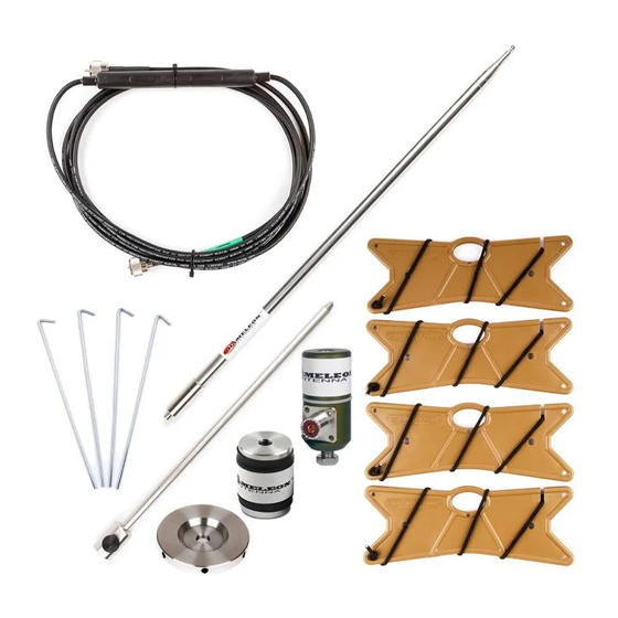
Antenna – part of the Modular Portable Antenna System (MPAS) family of portable antennas. Basic Vertical Antenna – The Basic Vertical (CHA BV) is an efficient single band at a time 40-10m resonant vertical antenna. The CHA BV is comprised of the following components: ✓... - Page 4 117 MHz continuously (including the 40-6m bands). ✓ Blank Adapter – The CHA BLANK is the core component of the CHA BV. It is a 3/8 in. X 24 to either SO-239 or BNC Adaptor. It enables use of MPAS components to create resonant portable vertical and wire antennas.
- Page 5 ✓ 12 ft. 6 in. Radials – A set of four 12 ft. 6 in. Radials (CHA B-RADIAL 12’6”) included with the CHA BV and CHA PRV and usable from 40 to 10m. • 25 ft. Counterpoise – The CHA COUNTERPOISE is a single 25 ft. counterpoise wire included in the MPAS 2.0 and other Chameleon Antenna...
-
Page 6: Hf Propagation
HF Propagation HF radio provides relatively inexpensive and reliable local, regional, national, and international voice and data communication capability. It is especially suitable for undeveloped areas where normal telecommunications are not available, too costly or scarce, or where the commercial telecommunications infrastructure has been damaged by a natural disaster or military conflict. - Page 7 days of in a month. The LUF is the frequency below which successful communications are lost due to ionospheric loses. The OWF, which is somewhere between the LUF and around 80% of the MUF, is the range of frequencies which can be used for reliable communication. If the LUF is above the MUF, HF sky wave propagation is unlikely to occur.
-
Page 8: Parts Of The Antenna
D. Spike Mount. The rugged Spike Mount (CHA SPIKE) enables easy in-ground mounting of the CHA BV antennas. E. Radials – A set of four 12 ft. 6 in. Radials (CHA B-RADIAL 12’6”) are included with the CHA BV and are usable from 40 to 10m. - Page 9 F. Puck Hub. The CHA PUCK HUB is a machined aluminum disk with six holes for Banana Jacks used to attach up to six radials to the antenna. G. Coaxial Connector. The Coaxial Connector is an SO-239 Female UHF Connector or a BNC Female Connector.
-
Page 10: Basic Vertical Antenna
Basic Vertical Antenna The Basic Vertical (CHA BV) is an efficient single band at a time 40-10m resonant vertical antenna. Figure (1) shows the Basic Vertical Configuration. With no loading coils, the CHA BV operates from 10 to 20 Meters. One Medium Loading Coil enables operation on 30 and 40 Meters. - Page 11 Figure 2. Basic Vertical Assembly. 6. Carefully extend the Telescoping Whip, 10. Carefully collapse the Telescoping Whip, one section at a time, starting from the starting at the top, until the tip is at the top, until it is fully extended. length measured in the previous step.
- Page 12 Table 2. Basic Vertical Initial Settings. 12. Connect the number of Radials (E), 15. Connect the Coaxial Cable (I) to the shown in table (2), to the Puck Hub using Coaxial Connector (G) on the side of the a Banana Plug (J). Blank Adapter.
-
Page 13: Inverted Lazy "L" Antenna
Inverted Lazy “L” Antenna The band coverage of the Basic Vertical (CHA BV) can be extended to 60, 75, and 80 Meters (one band at a time) by purchasing an optional 60 ft. Lazy Sloper kit (CHA LZ SLOPER [60’]). - Page 14 Note: It is highly recommended that you guy the Telescoping Whip to counterbalance lateral stress when using it with Lazy Sloper wire antenna. The Universal Guying System (CHA UGS) is available for purchase from Chameleon Antenna or your great dealer.
-
Page 15: Tuning Resonant Antennas
Tuning Resonant Antennas The lengths of the vertical telescopic whip, radial wires, and resonant wire antenna configurations were calculated using accepted formulas and then field tested. However, antenna height, ground conductivity, nearby objects, and other factors can cause the antenna to be detuned. -
Page 16: Recovery Procedure
Decreasing the length of the Telescoping Whip is easy - grasp the section just above the bottom section and carefully push it down the desired amount. Remeasure SWR. 2. Above the Band. The resonant frequency may be above or too high in the band indicating the antenna is too short. -
Page 17: Troubleshooting
8. If still not operational, replace Coaxial Cable. Most problems with antenna systems are caused by the coaxial cables and connectors. 9. If still not operational (SWR > 5:1), contact Chameleon Antenna support@chameleonantenna.com for technical support, be sure to include details on the antenna configuration, symptoms of the problem, and what steps you have taken. - Page 18 Figure 5. 40 Meter SWR Graph. Figure 6. 30 Meter SWR Graph. Figure 7. 20 Meter SWR Graph. Page 18...
- Page 19 Figure 8. 17 Meter SWR Graph. Figure 9. 15 Meter SWR Graph. Figure 10. 12 Meter SWR Graph. Page 19...
-
Page 20: References
Figure 11. 10 Meter SWR Graph. Figure 11. 80 Meter Inverted Lazy “L” SWR Graph. References 1. Silver, H. Ward (editor), 2013, 2014 ARRL Handbook for Radio Communications, 91 Edition, American Radio Relay League, Newington, CT. 2. 1987, Tactical Single-Channel Radio Communications Techniques (FM 24-18), Department of the Army, Washington, DC. -
Page 21: Chameleon Antenna Tm Products
Chameleon Antenna Products Go to http://chameleonantenna.com for information about quality antenna products available for purchase from Chameleon Antenna – The Portable Antenna Pioneer. Warranty information is available at http://chameleonantenna.com. Chameleon Antenna products are available from these great dealers: DX ENGINEERING...
Need help?
Do you have a question about the CHA BV and is the answer not in the manual?
Questions and answers