
Related Manuals for Chameleon Antenna CHA EMCOMM II V2


Summary of Contents for Chameleon Antenna CHA EMCOMM II V2
- Page 1 Portable HF Antenna (CHA EMCOMM II V2) Operator’s Manual Nevada - USA WWW.CHAMELEONANTENNA.COM VERSATILE – DEPENDABLE – STEALTH – BUILT TO LAST Revised November 7, 2020...
-
Page 2: Table Of Contents
References .............................. 15 Chameleon Antenna Products ......................16 Be aware of overhead power lines when you are deploying the CHA EMCOMM II V2. You could be electrocuted if the antenna gets near or contacts overhead power lines. Photographs and diagrams in this manual may vary slightly from current production units due to manufacturing changes that do not affect the form, fit, or function of the product. -
Page 3: Introduction
EMCOMM II V2 is configurable to facilitate Near-Vertical Incident Sky wave (NVIS) communication and is totally waterproof. The CHA EMCOMM II V2 does not require any ground plane but will perform better with one (a ground terminal is available for that purpose). This antenna requires a wide range antenna tuner or coupler. - Page 4 The frequency selected must be below the critical frequency, so NVIS can normally only be used on frequencies from around 2 to 10 MHz. Frequencies of 2 – 4 MHz are typical at night and 4 – 8 MHz during the day. CHA EMCOMM II V2 Page 4...
-
Page 5: Parts Of The Antenna
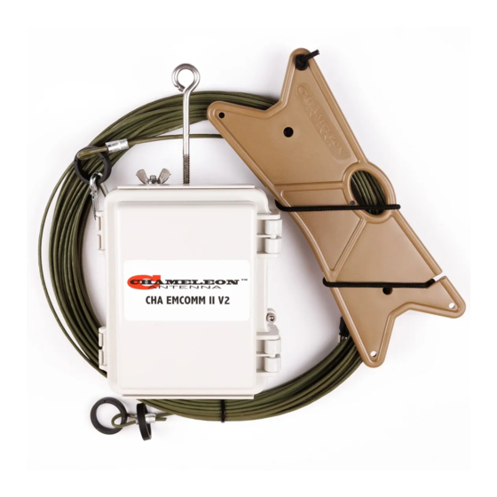
. EMCOMM II V2 Components Plate 1 a. Matching Transformer The Matching Transformer, see plate (1), provides impedance matching for the CHA EMCOMM II V2. b. Antenna Wire The Antenna Wire, see plate (2), is a 60 foot length of insulated wire. - Page 6 Transformer (a). Bottom Transformer Connection The Bottom Transformer Connection is located on the bottom of the Matching Transformer (a). Transformer Eyebolt The Transformer Eyebolt is located on the top of the Matching Transformer (a). CHA EMCOMM II V2 Page 6...
-
Page 7: Antenna Configurations
Antenna Configurations Using the supplied components, the CHA EMCOMM II V2 can be deployed into a number of useful configurations. Three configurations, see table (2), are described in this manual, each with unique performance characteristics. The table can assist the operator to quickly select the most appropriate antenna configuration to meet their operational requirements. - Page 8 13. If using a counterpoise, extend it along the 4. Connect the Wire Connector from the ground under the raised portion of Antenna Wire to the Top Transformer antenna. Connection (h). Tighten the wing nut finger 14. Perform operational test. tight. CHA EMCOMM II V2 Page 8...
-
Page 9: Sloping Wire
Sloping Wire The CHA EMCOMM II V2 Sloping Wire configuration, see figure (3), is a broadband short to medium range HF antenna. It is designed to provide acceptable ground wave and sky wave propagation. This configuration is predominately omnidirectional, becoming slightly bidirectional towards both ends as the frequency increases. -
Page 10: Inverted "L
Inverted “L” The CHA EMCOMM II V2 Inverted “L” configuration, see figure (5), is a broadband short to medium range HF antenna. This configuration tends to be unidirectional, favoring the horizontal end of the antenna. It also provides effective ground waves communication during the day time on frequencies between 1.8 –... -
Page 11: Recovery Procedure
15. Perform operational test. Raise the Antenna. Recovery Procedure To recover the CHA EMCOMM II V2, perform the following steps: 1. Disconnect the Coaxial Cable from the radio set. 2. Lower the antenna to the ground. 3. Disconnect the Coaxial Cable from the Matching Transformer (a). -
Page 12: Troubleshooting
SWR: Subject to frequency and configuration, see red (bottom) line in figure (6). Figure 6. SWR vs Frequency Graph. • RF Connection: UHF Plug (PL-259) • Length: 60 ft (maximum) and around 35 ft (minimum) CHA EMCOMM II V2 Page 12... -
Page 13: Accessories
Color: Subdued Hues. • Figures (7) through (9) show Far Field plots for the various antenna configurations Accessories The following accessories are available for purchase from Chameleon Antenna . Please contact us at support@chameleonantenna.com for current prices and availability. •... - Page 14 Figure 8 Inverted “L” Far Field Plots, 3.7 (left) and 7 (right) MHz. Figure 9. Horizontal NVIS Far Field Plots, 3.7 (left) and 7 (right) MHz. CHA EMCOMM II V2 Page 14...
-
Page 15: References
2. 1987, Tactical Single-Channel Radio Communications Techniques (FM 24-18), Department of the Army, Washington, DC. 3. Turkes, Gurkan, 1990, Tactical HF Field Expedient Antenna Performance Volume I Thesis, U.S. Naval Post Graduate School, Monterey, CA. CHA EMCOMM II V2 Page 15... -
Page 16: Chameleon Antenna Tm Products
Products Need a great antenna to go with your great mast? Go to http://chameleonantenna.com for information about quality antenna products available for purchase from Chameleon Antenna – The Portable Antenna Pioneer. Chameleon Antenna products are available from these great dealers:...
Need help?
Do you have a question about the CHA EMCOMM II V2 and is the answer not in the manual?
Questions and answers