
Related Manuals for Chameleon Antenna CHA LEFS 4010


Summary of Contents for Chameleon Antenna CHA LEFS 4010
- Page 1 Lightweight End Fed Half Wave Sloper (CHA LEFS 4010) Operator’s Manual Nevada - USA WWW.CHAMELEONANTENNA.COM VERSATILE – DEPENDABLE – STEALTH – BUILT TO LAST...
-
Page 2: Table Of Contents
All information on this product and the product itself is the property of and is proprietary to Chameleon Antenna Specifications are subject to change without prior notice. -
Page 3: Introduction
Parks on the Air (POTA), Summits on the Air (SOTA) and other hiking and biking outdoor adventures. Leave the tuner and SWR meter at home – just pack your radio and the CHA LEFS 4010 and... - Page 4 CHA LEFS 4010 configurations will support their communication requirements. HF radio waves propagate from the transmitting antenna to the receiving antenna using two methods: ground waves and sky waves.
-
Page 5: Parts Of The Antenna
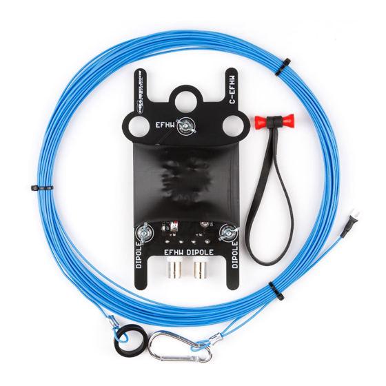
MHz during the day. Parts of the Antenna The CHA LEFS 4010 is comprised of the following components, see plate (2). The letter references are used to identify components of the antenna in the detailed installation instructions. Plate 2. Components of the CHA LEFS 4010 Antenna. - Page 6 J. Dipole Attachment. The two Dipole Attachments are used to connect operator supplied and fabricated Antenna Wires when the CHA LEFS 4010 is configured as a Dipole. K. Dipole Coaxial Connector. The Dipole Coaxial Connector is located on the bottom of the End Assembly (next to the “EFHW”...
-
Page 7: Antenna Configurations
Antenna Configurations There are three basic configurations for the CHA LEFS 4010: End Fed Sloper, End Fed Horizontal, and Half Wave Dipole. Sloper Configuration Figure (1) shows the Sloper configuration, to which the installation instructions and specifications apply. The Sloper is a short to medium range antenna. The main advantage of the Sloper for portable operation is that it requires only one end support and is fast and easy to setup. - Page 8 12-15 feet at both ends, you can enhance NVIS propagation. You will need a support at both ends of the antenna, such as trees or telescopic fishing or kite poles and 50 feet of paracord. Figure 2. CHA LEFS 4010 Horizontal NVIS Configuration. CHA LEFS 4010 Page 8...
- Page 9 CW/DATA segment of the band, you will likely need to trim the antenna for resonance using an SWR meter or analyzer. To use the CHA LEFS 4010 as a dipole, connect the set of Antenna Wires to the wing nut connections on the End Assembly marked “DIPOLE” and connect the Coaxial Cable to the BNC Coaxial Connector marked “DIPOLE”.
-
Page 10: Sloper Installation
Sloper Installation Use the following procedure to install the CHA LEFS 4010 Sloper configuration. Refer to plate (2). Site Selection and Preparation. 1. Select a site to deploy the CHA LEFS 4010 8. Raise the End Assembly to the desired height Sloper configuration. -
Page 11: Troubleshooting
6. If SWR is greater than 3:1 on specified bands, replace Coaxial Cable. Most problems with antenna systems are caused by the coaxial cables and connectors. 7. If still not operational, contact Chameleon Antenna Technical Support. Explain to them what specifically does not work correctly about the antenna, the steps you have taken during troubleshooting, and those results. -
Page 12: Warranty
12 months from the date of purchase. To obtain warranty service, return all components of the system to Chameleon Antenna at your expense. Chameleon Antenna will repair or replace defective components and return the system to you at no charge. -
Page 13: Chameleon Antenna Tm Products
Chameleon Antenna Products Please go to http://chameleonantenna.com for information about additional quality antenna products available for purchase from Chameleon Antenna – The Portable Antenna Pioneer. References 1. Silver, H. Ward (editor), 2013, 2014 ARRL Handbook for Radio Communications, 91 Edition, American Radio Relay League, Newington, CT.
Need help?
Do you have a question about the CHA LEFS 4010 and is the answer not in the manual?
Questions and answers