
Related Manuals for Chameleon Antenna Tactical Dipole LITE


Summary of Contents for Chameleon Antenna Tactical Dipole LITE
- Page 1 Tactical Dipole LITE (CHA TD LITE) Operator’s Manual Nevada - USA WWW.CHAMELEONANTENNA.COM VERSATILE – DEPENDABLE – STEALTH – BUILT TO LAST...
-
Page 2: Table Of Contents
Recovery Procedure ..........................13 Troubleshooting ............................13 Specifications ............................13 Accessories .............................. 17 Chameleon Antenna Products ......................17 References .............................. 18 Be aware of overhead power lines when you are deploying the CHA TD LITE. You could be electrocuted if the antenna gets near or contacts overhead power lines. -
Page 3: Introduction
Establishment (ALE), frequency-hopping, and spread-spectrum modes when used with a wide range antenna tuner or coupler. The CHA TD LITE can be deployed by the operator in the field in less than 15 minutes, using almost any available support, with no masts or guying required. Antennas built by Chameleon Antenna are versatile, dependable, stealthy, and built to last. -
Page 4: Parts Of The Antenna
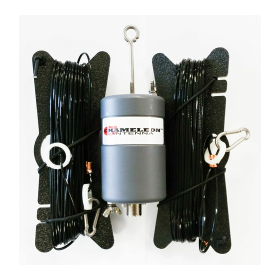
reflected from the Earth to the ionosphere again during multihop propagation for longer range communication. The most important thing for the operator to understand about HF radio wave propagation is the concept of Maximum Usable Frequency (MUF), Lowest Usable Frequency (LUF), and Optimal Working Frequency (OWF). The MUF is the frequency for which successful communications between two points is predicted on 50% of the days of in a month. - Page 5 Plate 1. Tactical Dipole LITE Components. UHF Socket The UHF Socket, SO-239, is located on the bottom of the Matching Transformer (a), see plate (2). h. Top Transformer Connection The Top Transformer Connection is located on the top of the Matching Transformer (a), see plate (2).
-
Page 6: Antenna Configurations
Plate 2 Matching Transformer, Side View (top), Bottom View (left) and Top View (right). Antenna Configurations Using the supplied components, the CHA TD LITE can be deployed into a number of configurations. Five configurations, see table (2), are described in this manual, each with unique performance characteristics. The table can assist the operator to quickly select the most appropriate antenna configuration to meet their operational requirements. -
Page 7: Sloping "V
complexity of site selection and setup. Most configuration and frequency combinations will require a wide range antenna tuner or coupler. Sloping “V” The CHA TD LITE Sloping “V” configuration, see figure (1), is a broadband medium to long range HF antenna. It provides good medium range sky wave propagation on all frequencies and long range sky wave propagation above 16 MHz. -
Page 8: Horizontal Dipole
6. Connect the Carabiner from the Wire Connector 12. Using a Bowline of similar knot, tie a short end of the other Antenna Wire to the Carabiner length of Paracord (around 4 feet) to Isolation from step (4). Loops (c) at the unconnected end of both 7. -
Page 9: Sloping Wire
Site Selection and Preparation. 1. Select a site to deploy the CHA TD LITE 6. Connect the Wire Connector of the Antenna Horizontal Dipole configuration, see figure (3). Wire to the Top Transformer Connection (h). A good site should have two trees or other Tighten the wing nut finger tight. -
Page 10: Inverted "L
Figure 4. Sloping Wire Configuration. Connect the Matching Transformer. Refer to figure 9. Connect the UHF Plug from the Coaxial Cable to (2) for steps (3) – (9). Socket Matching 3. Connect the Carabiner from the Wire Connector Transformer. end of an Antenna Wire to the Transformer Raise the Antenna. - Page 11 hasty deployment. It should be mounted at a height of 25 feet for best performance, but will provide good performance at a height of 10 to 20 feet and is usable when mounted as low as three feet. Figure 5. Inverted L Configuration. Site Selection and Preparation.
-
Page 12: Horizontal Nvis
Extend the Counterpoise. 18. Perform operational test. 17. Extend the counterpoise Antenna Wire from step (4) along the ground under the raised horizontal section of the antenna. Horizontal NVIS The CHA TD LITE Horizontal NVIS configuration, see figure (6), is a special configuration designed to provide good NVIS propagation on lower frequencies. -
Page 13: Recovery Procedure
11. Using a Bowline or similar knot, tie another long support using a Round Turn and two Half length of Paracord to the Isolation Loop (c) at Hitches, or similar knot. the free end of the Antenna Wire. Extend the Counterpoise. 12. - Page 14 • RF Connection: UHF Plug (PL-259) • SWR: Subject to frequency and configuration • Length: 120 ft (maximum), 60 ft (typical), 35 ft (minimum) • Footprint: 1,800 sq ft (maximum) • Weight: Less than 3 lbs • Personnel Requirements and Setup Time: one trained operator, less than 15 minutes •...
- Page 15 Figure 8. Horizontal; Dipole Far Field Plots, 7 (left) and 14 (right) MHz. Figure 9. Sloping Wire Far Field Plots, 7 (left) and 14 (right) MHz. CHA TD LITE Page 15...
- Page 16 Figure 10 Inverted “L” Far Field Plots, 3.7 (left) and 7 (right) MHz. Figure 11. Horizontal NVIS Far Field Plots, 3.7 (left) and 7 (right) MHz. CHA TD LITE Page 16...
-
Page 17: Accessories
Accessories The following accessories are available for purchase from Chameleon Antenna . Please contact us at support@chameleonantenna.com for current prices and availability. • Coaxial Cable Assembly. 50 feet of RG-58 with built-in RF isolation. Used to connect the CHA TD LITE to the radio set. -
Page 18: References
References 1. Silver, H. Ward (editor), 2013, 2014 ARRL Handbook for Radio Communications, 91 Edition, American Radio Relay League, Newington, CT. 2. 1987, Tactical Single-Channel Radio Communications Techniques (FM 24-18), Department of the Army, Washington, DC. 3. Turkes, Gurkan, 1990, Tactical HF Field Expedient Antenna Performance Volume I Thesis, U.S. Naval Post Graduate School, Monterey, CA.
Need help?
Do you have a question about the Tactical Dipole LITE and is the answer not in the manual?
Questions and answers