Table of Contents
Advertisement
CHILLERS
REVERSIBLE HEAT PUMPS
CONDENSING UNITS
• EXTERNAL UNITS
• HIGH EFFICIENCY
• HOT WATER PRODUCTION UP TO 50 °C
Aermec
participates in the EUROVENT Programme: LCP.
The products of interest can be found on:
www.eurovent-certification.com
INSTALLATION MANUAL
ANL
ANL-H
020-202
EN
1608. 6755441_02
Advertisement
Table of Contents

Summary of Contents for AERMEC ANL 020
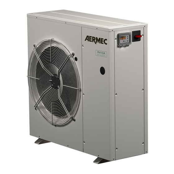
- Page 1 CHILLERS REVERSIBLE HEAT PUMPS CONDENSING UNITS ANL-H • EXTERNAL UNITS • HIGH EFFICIENCY 020-202 • HOT WATER PRODUCTION UP TO 50 °C Aermec participates in the EUROVENT Programme: LCP. The products of interest can be found on: www.eurovent-certification.com 1608. 6755441_02...
-
Page 2: General Instructions For The Installer
ANL-ANLH 020-202 GENERAL INSTRUCTIONS FOR THE INSTALLER The AERMEC ANL units are manufactured in accord- 1.2. SAFETY INSTRUCTIONS AND INSTALLA SAFETY ance with recognised technical and safety standards. TION STANDARDS Machinery directive They are designed for air conditioning and production... -
Page 3: Selection And Position Of Installation
ANL-ANLH 020-202 SELECTION AND POSITION OF INSTALLATION connections. In the case of installation where gusts of wind may oc- count the following points: cur adequately secure the unit using appropriate ties. The base must be able to support the weight of the Ensure the installation of the condensate drain tray on unit. - Page 4 6 DHW storage tank (not supplied) 8 System buffer tank (not supplied) 9 For further information refer to the specific VMF system documentation available on the website: www.aermec.com 10 Accessory required for the unit to communi- cate with the VMF system 1608. 6755441_02...
-
Page 5: System Charging
ANL-ANLH 020-202 4.5. SYSTEM CHARGING WARNING Before commencing the charging procedure position charging valve external to the unit Confirm the hydraulic integrity of the the main isolator of the unit in the OFF position. When water exits the terminal units air vents joints. -
Page 6: Electrical Connections
ANL-ANLH 020-202 ELECTRICAL CONNECTIONS The ANL units are fully factory wired and only require All electrical works must be carried out by PERSONNEL WITH THE APPROPRIATE LEGAL of an isolator, in accordance with the applicable wiring The design of the cabling and related components must be carried out by PERSONNEL WITH It is recommended to check the following items: APPROPRIATE QUALIFICATIONS TO DESIGN ELECTRICAL INSTALLATIONS, following interna- The electrical network is capable of meeting the... - Page 7 It is reminded that for units of this series, if requested evaporator outlet and observe the result on the by the Aermec client or the legal owner and only unit display panel; open the valve and reset the on ITALIAN territory, free start-up is provided by the flow trip alarm.
-
Page 8: Operating Characteristics
ANL-ANLH 020-202 • SEASON CHANGE controlled from the PR3 • ON/OFF CONTROL from the PR3 Confirm the selection pressing key and exit the menu with the key Once the PR3 remote panel is enabled the change of season selection can be made directly from the switch . -
Page 9: Routine Maintenance
ANL-ANLH 020-202 ROUTINE MAINTENANCE 10.4. MECHANICAL CHECKS WARNING It is forbidden to carry out any cleaning operation of compressors and electri- before isolating from the power supply cal panel and external panelling of the unit. Poor Confirm no voltage is present before commencing fixings cause noise and abnormal vibrations. -
Page 10: Procedure For Selection Of System Type
ANL-ANLH 020-202 PROCEDURE FOR SELECTION OF SYSTEM TYPE Several parameters of the MODU CONTROL board 13.1. HOW TO MODIFY A USER MENU 13.2. HOW TO MODIFY AN INSTALLER MENU have to be set, based on the type of system the unit is PARAMETER PARAMETER installed.


Need help?
Do you have a question about the ANL 020 and is the answer not in the manual?
Questions and answers