Table of Contents
Advertisement
Advertisement
Table of Contents

Related Manuals for AERMEC NRL FC 028


Summary of Contents for AERMEC NRL FC 028
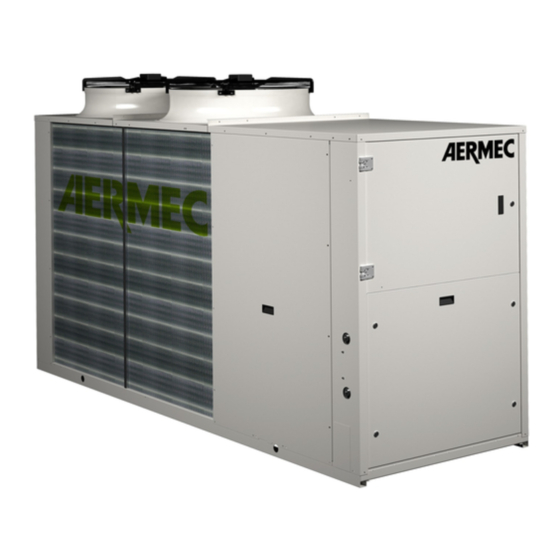
- Page 1 Installation and Maintenance Manual 60Hz INTERTEK AHRI FREE-COOLING SCROLL AXIAL FAN PLATE FREQUENCY CERTIFICATION CERTIFICATION COMPRESSOR EXCHANGER NRL FC 028-075 CHILLER • HIGH EFFICENCY • POWER SUPPLY 60Hz BARCODE 21.05 5641250_04 TRANSLATION FROM ORIGINAL...
- Page 3 AERMEC S.p.A AERMEC S.p.A. reserves the right at all times to make any modification for the improvement of its product and is not obliged to add these modification to machines of previous manufacture that have already been delivered or are being built.
-
Page 4: Table Of Contents
Description and choce of unit ............5 Hydraulic connection ..............14 9.1. Hydraulic connection NRL 0280-0350 FA ........14 Check list ................... 6 9.2. Hydraulic connection NRL 0500 - 0750 FA ........14 Principle of operation schemes ............7 Distribution of percentage weights on supportingpoints ....15 3.1. -
Page 5: Description And Choce Of Unit
DESCRIPTION AND CHOCE OF UNIT The NRL Free-cooling series appliances are water Models: chillers equipped with an external air cooling capacity NRL "F" free-cooling recovery system called "free-cooling". The water free-cooling system consists in integrating The versions can be in different set-ups at the same and eventually completely replacing the cooling capaci- time in order to satisfy a wide range of plant enginee- ty delivered by the compressors through an additional... -
Page 6: Check List
CHECK LIST Ciruit Components Cooling circuit Model with D Resistance carter compressor High pressure switch Low pressure switch High pressure trasducer Low pressure trasducer Solenoid valve of hot gas injecton By-pass valve of hot gas Exchanger (EV- EV/CN) Exchanger (desuperheater) Exchanger (glycol free) "F"... -
Page 7: Principle Of Operation Schemes
PRINCIPLE OF OPERATION SCHEMES 3.1. PRODUCTION OF COLD WATER ONLY THE SYSTEM Description Operation exchanger (EVAPORATION) SYSTEM SIDE Production cold water exchanger (CONDENSATION) SOURCE SIDE Heat exchange with the air exchanger (EVAPORATION FREE-COOLING) SYSTEM SIDE Production cold water Sign Description compressor Air side exchange Thermostatic valve... -
Page 8: Selection And Place Of Installation
After removal 329/2004). of packaging, movement of apparatus must be AERMEC will not assume any respon- − The support surface must be capable of carried out by qualified and adequately equipped sibility for damage due to failure to supporting the unit weight. -
Page 9: Dimension
DIMENSION 6.1. NRL 0280 - 0300 FE 1606 mm 1750 mm 63 in 69 in 2950 mm 3010 mm 116 in 119 in 1100 mm 1160 mm 43 in 46 in 6.2. NRL 0330 - 0350 FE 1606 mm 1750 mm 63 in 69 in 2950 mm... -
Page 10: Nrl 0600 - 0650 - 0700 Fa
6.4. NRL 0600 - 0650 - 0700 FA 1875 mm 74 in 1990 mm 78 in 4010 mm 4070 mm 158 in 160 in 1100 mm 1160 mm 43 in 46 in 6.5. NRL 0750 FA 1955 mm 77 in 4355 mm ATTENTION: 172 in... -
Page 11: Antivibration Positioning
ANTIVIBRATION POSITIONING 7.1. NRL 0280 - 0300 - 330 - 350 FE 200 mm 1275 mm 1275 mm 200 mm 8 in 50 in 50 in 8 in 200 mm 1275 mm 1275 mm 200 mm 8 in 50 in 50 in 8 in 7.2. -
Page 12: Nrl 0600 - 0650 - 0700 Fa
7.3. NRL 0600 - 0650 - 0700 FA 200 mm 2158 mm 1440 mm 200 mm 8 in 85 in 57 in 8 in 200 mm 2158 mm 1440 mm 200 mm 8 in 85 in 57 in 8 in 7.4. -
Page 13: Crate: Special Wood Cover For Transport (Accessory)
CRATE: SPECIAL WOOD COVER FOR TRANSPORT (ACCESSORY) CRATE A (in) B (in) C (in) CRATE02 87.9 138.7 50.4 CRATE03 87.9 180.1 50.4 CRATE04 95.7 184.0 66.2 MODELS CRATE 0280 FA-FE 0300 FA-FE 0330 FA-FE 0350 FA-FE 0500 FA-FE 0550 FA-FE 0600 FA-FE 0650... -
Page 14: Hydraulic Connection
HYDRAULIC CONNECTION 9.1. HYDRAULIC CONNECTION NRL 0280-0350 FA 9.2. HYDRAULIC CONNECTION NRL 0500 - 0750 FA WARNING: Clean the system carefully before connecting the unit. Cleaning will eliminate any residues suck as drops of solder, waste, rust or other impurities from the piping. -
Page 15: Distribution Of Percentage Weights On Supportingpoints
DISTRIBUTION OF PERCENTAGE WEIGHTS ON SUPPORTINGPOINTS TOP VIEW WEIGHT OF EMPTY UNITS CENTER OF PERCENTAGE OF WEIGHT WEIGHT GRAVITY DISTRIBUTION SUPPORTS (%) TYPE (lib) Gx mm NRL0280F 1847 1312 VT 17 NRL0280F 2255 1395 VT 13 NRL0280F 2178 1368 VT 13 NRL0280F 2001 1376... - Page 16 WEIGHT OF EMPTY UNITS PERCENTAGE OF WEIGHT CENTER OF DISTRIBUTION SUPPORTS WEIGHT GRAVITY TYPE (lib) Gx mm NRL0600F 3019 1701 8,0% 8,0% 32,8% 33,0% 9,1% 9,1% VT 22 NRL0600F 3526 1461 9,1% 6,9% 37,4% 28,4% 10,4% 7,9% VT 22 NRL0600F 3416 1506 8,9%...
-
Page 17: Hydraulic Circuit
HYDRAULIC CIRCUIT 11.1. HYDRAULIC CIRCUIT (VERSIONS P3-P4) hydraulic components NRL P3-P4 hydraulic components NOT SUPPLIED STANDARD COMPONENT ATTENTION Exchanger plate The choice and the installation of Free-cooling coil components external to the NRL Water filter up to the installer, who must ope- rate according to the rules of good Ball stop technical design and in compliance... -
Page 18: Hydraulic Circuit (Versions 03-04)
11.2. HYDRAULIC CIRCUIT (VERSIONS 03-04) hydraulic components NRL 03-04 hydraulic components NOT SUPPLIED STANDARD COMPONENT Exchanger plate Free-cooling coil ATTENTION The choice and the installation of Water filter components external to the NRL Ball stop up to the installer, who must ope- rate according to the rules of good Flow switch technical design and in compliance... -
Page 19: System Load
11.3. SYSTEM LOAD 11.4. EMPTYING THE SYSTEM ATTENTION − Before starting the load, check that the system − Before starting to drain the system, turn "off" the In case of version with pumping drain tap is closed. unit unit, without standby pump, it is −... -
Page 20: Electrical Wirings
ELECTRICAL WIRINGS • the length • the type of cable • Absorption of the unit and its physical position, and The default NRL chillers are completely wired and ATTENTION room temperature. only need the connection to the power supply net, All electrical operations must be WARNING: downstream to a group switch, according to the to the... - Page 21 Model Alimentation 208/3/60Hz MODEL WITHOUT PUMP - "I" EC INVERTER FAN 208V 208V 208V MODEL WITH HIGH HEAD PUMP (P3-P4-03-04) - "I" EC INVERTER FAN 208V 208V 208V Alimentation 230/3/60Hz MODEL WITHOUT PUMP - "I" EC INVERTER FAN 230V 230V 230V MODEL WITH HIGH HEAD PUMP (P3-P4-03-04) - "I"...
-
Page 22: Electronic Control (Pco 5 )
ELECTRONIC CONTROL(PCO ELECTRONIC CONTROL (pCO5) START-UP ANTI-FREEZE ALARM WATER FLOW ALARM CIRCULATING PUMP Reference parameters: If the water fl ow rate is not suffi cient, this safety stops the compressors and the pump Compressor BLOCK - OFF Turn the unit on (ON) BLOCCK - OFF Temperature >... - Page 23 Cavo telefonico cavo telefonico I/ O prog. Cavo telefonico S90CONN*: cavo di collegame nto • The address to enable remote panel is 31 For more informati on, refer to the wiring diagrams in the selecti on program or site www.aermec.com...
-
Page 24: User Interface (Pgd1)
User Interface (PGD1) USER INTERFACE (PGD1) The unit control panel allows the quick se� ng and INTERFACE CONTROL KEYS display of the unit’s opera� ng parameters. The board memorises all the default se� ngs and any Control Keys Control Keys modifi... -
Page 25: Start-Up Procedure
Start-up procedure START-UP PROCEDURE any � me through the appropriate screen contained A� er having powered up the unit the control board will select the system language. These screens are detailed in the Installer menu. carry out preliminary opera� ons before being ready in the table below. -
Page 26: Menu Structure And Navigation
MENU STRUCTURE AND NAVIGATION Menu structure and naviga� on Both the functi ons to control the unit and the operati ng informati on The opera� ng menus are arranged as in the following drawing: are displayed on the unit mounted control panel. All the functi ons and informati on are arranged in screens which in turn are grouped into menus. -
Page 27: User Operating Procedures
User operating procedures USER OPERATING PROCEDURES To check or modify the operati ng parameters of the unit it is necessary to use the interface of the control panel on the unit. The basic operati ons that the user must be capable of, for the correct use of the unit, are: (1) Moving from one menu to the next. - Page 28 Via Roma, 996 37040 Bevilacqua (VR) - Italia Tel. + 39 0442 633111 Fax +39 0442 93577 marketing@aermec.com www.aermec.com Aermec reserves the right to make all modification deemed necessary for improving the product at any time with any modification of technical data.
Need help?
Do you have a question about the NRL FC 028 and is the answer not in the manual?
Questions and answers