Lightspeed Cat 855 Installation Manual
Classroom audio systems cat 800 series;
Hide thumbs
Also See for Cat 855:
- User manual (41 pages) ,
- User manual (48 pages) ,
- Installation instructions (2 pages)
Table of Contents
Advertisement
Quick Links
Download this manual
See also:
User Manual
Advertisement
Table of Contents

Related Manuals for Lightspeed Cat 855


Summary of Contents for Lightspeed Cat 855
- Page 1 Cat 800 Series Classroom Audio Systems Cat 855 Cat 885 I n s t a l l a t i o n M a n u a l...
-
Page 2: Important Safety Instructions
IMPORTANT SAFETY INSTRUCTIONS Read these instructions. 13. Unplug this apparatus during lightning storms or when Keep these instructions. unused for long periods of Heed all warnings. time. Follow all instructions. 14. Refer all servicing to qualified service personnel. Servicing is Do not use the apparatus required when the apparatus near water. -
Page 3: Table Of Contents
TABLE OF CONTENTS SECTION 1: Important Safety Instructions Overview System Components and Unpacking SECTION 2: 1. Location of the Amplifier Installation Planning 2. Installation of Amplifier Wall Bracket 800WB 3. Installation of Amplifier Wall Bracket 855WB SECTION 3: ISR Sensor/Receiver Location & Installation ISR Sensor/Receiver 1. -
Page 4: System Components And Unpacking
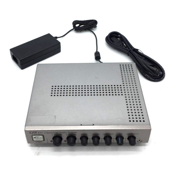
SECTION 1: OVERVIEW SYSTEM COMPONENTS AND UNPACKING The standard configuration of the Cat 800 system will contain: Cat 855 Amplifier Cat 885 Amplifier Amplifier Power Supply ISR Infrared Sensor/ Receiver and Cable... - Page 5 SYSTEM COMPONENTS AND UNPACKING CONT’D Redmike® Classroom Microphone Cradle Charger and Power Supply Wall Bracket for Cat 855 Amplifier Only...
- Page 6 SYSTEM COMPONENTS AND UNPACKING CONT’D Speakers Systems can be configured with a variety of different speaker types, including the following: TCQ (x 1) DRQ (x 4) 4jCS (x4) WMQ (x 4) (plenum rated)
- Page 7 SYSTEM COMPONENTS AND UNPACKING CONT’D Standard Components for 855 or 885 855 (or) Audio amplifier/mixer Audio amplifier/mixer 24V-2.5-NA 24V/2.5A power supply for 855/885 in U.S. and Canada 24V-2.5-_ 24V/2.5A power supplyfor 855/885, specify country Infrared sensor/receiver with mounting bracket CA-P5E50 50’...
-
Page 8: Location Of The Amplifier
Media Cabinet Set-up Wall-mount Set-up The optional Lightspeed wall shelf (part #800WB) is specifically designed to support the Cat 885. The standard Lightspeed wall shelf (part #855WB) is designed to support the Cat 855. Avoid Separated Set-ups Components should be housed together. - Page 9 2. INSTALLATION OF AMPLIFIER WALL-MOUNT BRACKET 800WB Optional 800WB for wall mounting Specifications: the Cat 885. Dimensions (D x W x H): 11” x 20.7” x 5.5” Weight: 5.15 lbs Load Capacity: 25 lbs Designed for: Cat 885 Installation Instructions: Recommended tools: Screwdriver, hammer, pencil, level 1.
- Page 10 2. INSTALLATION OF AMPLIFIER WALL-MOUNT BRACKET 800WB cont’d 4. Use level to determine that the shelf is straight. 5. The back of the shelf (the portion that is flush against the wall) has four mounting holes. Using a pencil, mark the location of the mounting holes onto the wall.
- Page 11 4. Secure the Cat 855 to the bracket by tightening the screw on the bottom. 5. Now that the Cat 855 is secure, it can be slowly pulled out and pivoted for better access to the back panel. Push the Cat 855 back in, to lock into place.
-
Page 12: Isr Sensor/Receiver Location & Installation
SECTION 3: ISR SENSOR/RECEIVER LOCATION & INSTALLATION Sensor location is very important for optimum performance of the Classroom Audio System. • BEST: On the ceiling at or near the middle of the classroom. • GOOD: High and centered on the long wall. •... -
Page 13: Isr Sensor/Receiver Installation
1. ISR SENSOR/RECEIVER INSTALLATION Once you find a suitable location for the ISR, follow these instructions to mount it. There are different instructions for mounting depending on if the ISR will be mounted to a suspended ceiling grid or secured to a wall / solid vertical surface. - Page 14 1. ISR SENSOR/RECEIVER INSTALLATION cont’d 1b.WALL/SOLID CEILING MOUNT 1. Screw the bracket to a place high on the wall or in the middle of the solid ceiling. Mount the bracket horizontally. 2. Uncoil the Cat5e sensor cable. Connect one end of the cable to the ISR. Route the wire back to the amplifier, securing it along with way using surface raceway where possible.
-
Page 15: Isr Connection To Amplifier
2. ISR CONNECTION TO AMPLIFIER 1. Ensure the power is still switched off. 2. Check the connection from the ISR to the amplifier. Ensure the sensor cable is securely attached and locked into place. 855/885 Amplifier ISR Sensor/Receiver... -
Page 16: Connecting The Power Supply
3. CONNECTING THE POWER SUPPLY 1. Ensure the power button is in the off position. 2. Connect the DC end of the power supply to the black power jack labeled DC POWER. 3. Connect the black AC power cable from the power supply to a wall outlet. -
Page 17: Tcq Multimedia Ceiling Speaker Installation Instructions
SECTION 4: SPEAKER LOCATION & INSTALLATION Tools and equipment that may be needed to install the speakers outlined in this manual: • Straight edge • Utility knife or drywall saw • Screwdriver, standard & phillips • Screwdriver, small jewelers type ,1/8” wide tip •... - Page 18 TCQ SPEAKER INSTALLATION INTRUCTIONS CONT’D 1. SELECTING SPEAKER Figure 1: Identify the center of the room MOUNTING LOCATIONS 1. One TCQ speaker will distribute sound throughout a classroom of up to 1200 square feet (112 sq m). The location of the speaker is important to ensure even sound distribution.
- Page 19 TCQ SPEAKER INSTALLATION INTRUCTIONS CONT’D Figure 3: Create Two 2’ x 2’ Openings 2. Set the ceiling tile on a flat work surface with the patterned side facing down. Existing T-Bar 3. Using a straight edge, cut the 2’ x 4’ ceiling Tile Grid tile in half (see figure 2) leaving two 2’...
- Page 20 TCQ SPEAKER INSTALLATION INTRUCTIONS CONT’D 5. Lift the TCQ up and lay it into the desired Figure 5: Set speaker into ceiling grid location. (see figure 5) Caution: Make sure the TCQ is stable on the grid rails with side brackets capturing the t-bar grid.
- Page 21 600mm x 600mm ceiling grid. Remove the spacer brackets from each of the four sides of the TCQ. Note: If your ceiling grid is any other dimension than mentioned above, contact your local Lightspeed reseller. INSTALLING SAFETY WIRE: Figure 6: Looping the Safety Wire Through the Tab 1.
- Page 22 TCQ SPEAKER INSTALLATION (OUTSIDE U.S. & CANADA ONLY) cont’d 1. Pull one of the tabs up on the TCQ (located in opposite corners) and loop the other end of the safety wire through the tab. Pull the wire through until it is taut and twist it around itself at least five times to secure the TCQ.
- Page 23 TCQ SPEAKER INSTALLATION cont’d 3. OPTIONAL CONDUIT CONNECTION 1. Locate and uncoil the Cat5e sensor cable coming out of the back of the TCQ speaker. 2. Thread this cable through a standard sin- gle-gang -box with ears (not provided). 3. Locate the 15m 18 awg, 2 conductor plenum-rated speaker wire (or supply, if not ordered) and the green euro-style connector located on the back of the...
-
Page 24: Drq Ceiling Speaker Installation Instructions
DRQ CEILING SPEAKER INSTALLATION INSTRUCTIONS Tools and Equipment Speaker Components • Small flathead screwdriver • (4) DRQ speakers • Philips screwdriver • (4) Tile bridges • Marker or pencil • (2) 30 ft bundles of plenum-rated speaker wire (if ordered) marked with a white •... - Page 25 DRQ CEILING SPEAKER INSTALLATION INSTRUCTIONS cont’d 4. Turn the tile on its side and insert the Figure 3: Remove the Grille speaker into the front side of the tile. Place the tile bridge around the back- side of the speaker, oriented horizontally across the tile (as shown in Figure 2).
- Page 26 DRQ CEILING SPEAKER INSTALLATION INSTRUCTIONS cont’d 7. Connect the wire to the input set of -+ connectors , paying attention to polarity and tighten the screws on top to secure. 8. Repeat 2 through 7 to connect Speakers #3 and #4. Note that only two speakers can be wired together per amplifer out- put (minimum 4 ohm load).
-
Page 27: Wmq Wall Speaker Installation Instructions
WMQ WALL SPEAKER INSTALLATION INSTRUCTIONS Tools and Equipment WMQ Speaker • Small flathead screwdriver • Drill with 3/16” (.1875mm) drill bit • Phillips head screwdriver • Marker or pencil Speaker Components Figure 1: Speaker Placement • (4) WMQ speakers Optimum Good •... - Page 28 WMQ WALL SPEAKER INSTALLATION INSTRUCTIONS cont’d 7. If the walls are drywall, drill pilot holes Figure 2: Mounting the Speaker with a 3/16” (.1875mm) drill bit, then screw in the supplied drywall anchors. 8. While holding the bracket against the wall, drill the mounting screws into the drywall anchors (or directly into a stud).
- Page 29 WMQ WALL SPEAKER INSTALLATION INSTRUCTIONS cont’d 2. CONNECTING AND ROUTING SPEAKER WIRE Locate the plenum rated wire included with 5. Route the wire to Speaker #2. Secure and the speaker components (If ordered). conceal wire as needed. 1. Distribute the appropriate lengths of 6.
-
Page 30: 4Js Ceiling Speaker Installation Instructions (Plenum Rated)
4JCS CEILING SPEAKER INSTALLATION INSTRUCTIONS (Plenum Rated) Tools and Equipment Speaker Components • Straight edge • (4) Speaker/baffle assembly • (4) Tile bridge • Marker • (4) Speaker enclosure • Scissors (template) • (16) Mounting screws • Utility knife • (8) Wire nuts •... - Page 31 4JCS CEILING SPEAKER INSTALLATION INSTRUCTIONS (Plenum Rated) cont’d 4JCS Locations 1. SELECTING SPEAKER Figure 2: Speaker Placement MOUNTING LOCATIONS 4JCS Locations Ceiling Level A standard system includes 4 ceiling speak- ers for rooms up to 1600 sq ft (148sqm) with a ceiling height of 9-12 feet (2.75m - 3.75m).
- Page 32 4JCS CEILING SPEAKER INSTALLATION INSTRUCTIONS (Plenum Rated) cont’d 3. Using a utility knife or jigsaw, cut out the circular hole in the center of the tile as neatly as possible. The speaker baffle will cover up some minor rough edges. NOTE: To ensure the hole is large enough, cut slightly outside template lines (see figure 3c).
- Page 33 4JCS CEILING SPEAKER INSTALLATION INSTRUCTIONS (Plenum Rated) cont’d 3. CONNECTING AND ROUTING SPEAKER WIRE Prep two conductor 18 awg plenum rated speaker wire ends for insertion into the speaker connectors. NOTE: it is advised to prep and connect each speaker at ground level.
- Page 34 4JCS CEILING SPEAKER INSTALLATION INSTRUCTIONS (Plenum Rated) cont’d 5. Install the speaker enclosure on the tile bridge securing it in place by turning the enclosure clockwise (see figure 5). 6. Install speaker #1 with tile into the ceiling grid and route cabling (following local building codes) to speaker #2.
-
Page 35: Connecting Wire To Amplifier
CONNECTING WIRE TO AMPLIFIER Cat 855 (Figure 5) 1. Unplug the euro-block SPEAKER OUT- Figure 5: Connecting Speaker Wire to Back PUT connector from the amplifier. of 855 or 885 2. Insert the two wires into the connector, paying close attention to polarity (+ - - +). -
Page 36: Charging The Redmike And Redmike Vc
Replacement AA NiMH batteries may only be purchased through Lightspeed Technologies (part # NH2A27). Do not attempt to charge alkaline batteries. They can overheat and expand creating a significant hazard and damaging the microphone (this is not covered by warranty). - Page 37 1. CHARGING THE REDMIKE AND REDMIKE VC cont’d Redmike VC : Charging Before use, the Redmike VC should be charged. See page 37 and follow the same instructions for the Redmike. Redmike VC : Initial Set-up See page 39 and follow the same instructions for the Redmike to setup the Redmike VC.
-
Page 38: Operating The Redmike
2. OPERATING THE REDMIKE Once the Redmike is charged, follow these steps to set it up for use. 1. Turn the amplifier power on. The blue LED will glow. 2. Remove the Redmike from the charging cradle and turn it on. 3. -
Page 39: Charging The Redmike Share
3. CHARGING THE REDMIKE SHARE 1. Ensure that the Redmike Share is turned off. 2. Make sure the cradle charger is plugged into a wall outlet. Connect one end of the charging cable into the jack labeled CHARGER on the bottom of the Redmike Share. -
Page 40: Operating The Redmike Share
4. OPERATING THE REDMIKE SHARE 1. Ensure the 855 or 885 is on. The LED on the power switch will glow blue. 2. Turn on the Redmike Share by sliding the switch to the up position. 3. Grip the barrel in the center section. Avoid covering the infrared emitters circling the base of the screened microphone element. -
Page 41: Audio Integration
5. AUDIO INTEGRATION The next step in setting up your system is to connect it to the other multimedia devices in your classroom. You may have a computer, television, DVD/VCR player, a visual projection system or other devices. Below are instructions on how to integrate TV/VCR, CD/DVD or computer directly into the amplifier. -
Page 42: Pagefirst Installation For
SECTION 6: INSTALLATION INSTRUCTIONS FOR OPTIONAL EQUIPMENT 1. PAGEFIRST INSTALLA- Figure 1: Hanging the Sensor Clip TION FOR 855/885 The following components are included when the PageFirst option is purchased as an add-on: • PageFirst sensor clip with wire pigtail (PFSC) •... - Page 43 1. PAGEFIRST INSTALLATION CONT’D 1c. CONNECT PAGEFIRST Figure 2: Connecting Pagefirst to amplifier SENSOR TO AMPLIFIER The sensor needs to be hard-wired back to the amplifier. 1. Insert the euro-block connector of the wire into the PageFirst input jack on the amplifier.
- Page 44 2. INITIAL SET-UP: OPTIONAL IR MEDIA CONNECTOR 1. Turn off the second microphone. The iR Media Connector uses the same channel (channel B) as the optional second microphone (Redmike or Redmike Share). As a result, they cannot be used simultaneously. If you have a second microphone, turn it off before transmitting audio from the iRMC.
- Page 45 2a. OPTIONAL IR MEDIA CONNECTOR AUDIO INTEGRATION The iRMC is designed to integrate with the Cat 855 or 885 and multiple audio sources, allowing other instructional technologies to be clearly heard throughout the classroom. Video In Projector Projector ISR Sensor...
- Page 46 3. CAT 855/885 - MULTIPLE SENSOR INSTALLATION INSTRUCTIONS For large room applications or rooms needing improved IR coverage, the Cat 855 & 885 utilize an ISR module for the primary sensor/receiver and an SR70F IR sensor for any additional sen- sors needed.
- Page 47 3. CAT 855/885 - MULTIPLE SENSOR INSTALLATION INSTRUCTIONS cont’d 3c. ISR CONNECTION FOR 855/885 1. Attach a 50ft Cat5e cable from the “Sen- sor Input” on the back of the amplifer and run the cable using standard wiring methods acceptable to local codes up to the RJ45 connector on the back of the ISR module (See figure 2).
-
Page 48: Common Problems And Solutions
If you review these instructions and still have questions, write down the serial number and model number of your system and call Lightspeed Technical Services at 800.732.8999, 5 a.m. – 5 p.m., PST. Customers outside the U.S. should contact their local reseller. - Page 49 This page intentionally left blank.
- Page 50 This page intentionally left blank.
- Page 52 LIGHTSPE ED TECHNO LO G I E S 1 15 0 9 SW HE RM AN ROA D / T U ALATI N, OR 97062 TO LL FRE E: 800.732.8999 / P H ON E: 503. 684. 553 8 / FA X : 5 03 .6 84.3197 LIG HTSPE ED- TEK .COM IG0456US01-3...
Need help?
Do you have a question about the Cat 855 and is the answer not in the manual?
Questions and answers