Lightspeed 800 Series User Manual
Classroom audio systems
Hide thumbs
Also See for 800 Series:
- Installation instructions (2 pages) ,
- Installation instructions (2 pages)
Table of Contents
Advertisement
Quick Links
Advertisement
Table of Contents

Related Manuals for Lightspeed 800 Series


Summary of Contents for Lightspeed 800 Series
- Page 1 800 Series Classroom Audio Systems 820iR CAT 855 CAT 885 U s e r M a n u a l...
-
Page 2: Table Of Contents
TABLE OF CONTENTS SECTION 1: Important Safety Instructions Overview System Components and Unpacking Optional Accessories 820iR: Front Panel Controls 820iR: Rear Panel Controls 820iR: Infrared Sensor (SR70F) CAT 855: Front Panel Controls CAT 855: Back Panel Controls CAT 885: Front Panel Controls CAT 885: Back Panel Controls CAT 855/885: Infrared Sensor/Receiver REDMIKE Controls and Connections... -
Page 3: Important Safety Instructions
IMPORTANT SAFETY INSTRUCTIONS 12. Use only with a cart, Read these instructions. stand, tripod, bracket or Keep these instructions. table specified by the manufacturer, or sold with Heed all warnings. the apparatus. When a cart Follow all instructions. is used, use caution when Do not use the apparatus moving the cart/apparatus near water. -
Page 4: Overview
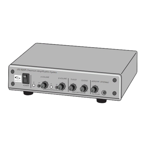
SECTION 1: OVERVIEW SYSTEM COMPONENTS AND UNPACKING The standard configuration of the 820iR will contain: LES 820iR Classroom Amplification System A VOLUME B VOLUME TV/VCR CD/DVD ASSISTIVE LISTENING POWER WIRELESS MICROPHONE VOLUME ALD VOLUME AUDIO INPUT VOLUME 820iR Amplifier Amplifier Power Supply SR70F Infrared Sensor and Cable... -
Page 5: System Components And Unpacking
SYSTEM COMPONENTS AND UNPACKING CONT’D The standard configuration of the CAT 855 or 885 Amplifier will contain: Amplifier Power Supply ISR Infrared Sensor/ Receiver and Cable REDMIKE® Classroom Microphone Cradle Charger and Power Supply Wall Bracket (855WB) for CAT 855 Amplifier... - Page 6 SYSTEM COMPONENTS AND UNPACKING CONT’D Speakers Systems can be configured with a variety of different speaker types, including the following: DRQ (x 4) NXQ (x 1) 4jCS (x4) WMQ (x 4) (plenum rated) (When shipped with 820iR, TCQ (x 1) TCQ does not include ISR.)
- Page 7 SYSTEM COMPONENTS AND UNPACKING CONT’D Standard Components 820iR L820 Infrared receiver/amplifier/mixer 24V-2.5-NA 24V/2.5A power supply for 820iR in U.S. and Canada 24V-2.5-_ 24V/2.5A power supply for 820iR, specify country SR70F Infrared sensor with mounting bracket PC50F 50’ plenum-rated sensor cable RMT2 REDMIKE classroom microphone with battery NH2A27...
-
Page 8: Optional Accessories
OPTIONAL ACCESSORIES CONT’D Optional equipment which may be part of your 820/885/855 system: REDMIKE® VC Volume Control Microphone (RMV2) LT71 LT-71 LightMic and Charger Cable (LT71) REDMIKE Share Handheld Mic & Charger Cable (RMS2) Infrared Media Connector (IRMC2) Page First Kit (PFSC) for 855/885 Amplifier Shelf... - Page 9 This jack sends audio to detected. external equipment such as an assistive listening device 4. A VOLUME: Controls the like Lightspeed’s 370 Personal volume level of the teacher FM System. Use the volume microphone (set to channel A). control to set the optimum Rotating the knob clockwise signal level for the device.
- Page 10 820iR: REAR PANEL CONTROLS AUDIO INPUT TV/VCR CD/DVD 2.06/2.54 SPEAKER OUTPUTS CHARGERS POWER AUDIO INPUT SENSOR INPUT TV/VCR CD/DVD 2.06/2.54 UTPUTS CHARGERS POWER SENSOR SHORT 1. SPEAKER OUTPUTS (1–4): 4. AUDIO INPUTS: These binding post connectors These connections accept are used to connect the an audio signal from other 820iR to the loudspeaker(s).
- Page 11 820iR: INFRARED SENSOR (SR70F) 1. POWER INDICATOR: This light will glow red when theSR70F is receiving power from the 820iR. 2. F-CONNECTOR: Connect the PC50F plenum-rated sensor cable to this connection to send audio from the microphones to the 820IR amplifier.
- Page 12 3. A VOLUME: Controls the assistive listening device like volume of the teacher Lightspeed’s 370 Personal microphone (set to channel A). FM System. Use the volume Rotating the knob clockwise control to set the optimum increases output level.
- Page 13 CAT 855: BACK PANEL CONTROLS 1. SPEAKER OUTPUTS (1-2): system to produce optimum This euro-block connector is audio quality from the used to connect the CAT 855 microphone(s). to the loudspeaker(s). Up to 6. AUX OUT AND VOL: This two 8-ohm speakers can be jack sends audio to external connected to each output.
- Page 14 Lightspeed’s 370 Personal (set to channel B). Rotating FM System. Use the volume the knob clockwise increases control to set the optimum output level.
- Page 15 CAT 885: BACK PANEL CONTROLS 1. SPEAKER VOLUME (1-6): 3. MONO/STEREO SWITCH: This Controls the output volume switch toggles between mono of the corresponding speaker. and stereo speaker output for Fully clockwise represents channels 5 (left) and 6 (right). maximum audio level supplied This switch impacts only the to the speaker.
- Page 16 8. 805iX INPUT: This input 12. SENSOR SHORT: This LED jack allows for interface glows red when there is a with the Lightspeed 805iX short in the ISR or cable. The wireless microphone system, system will not operate, but which adds two additional is protected from damage microphone channels.
- Page 17 CAT 855/885: INFRARED SENSOR/ RECEIVER 1. POWER INDICATOR: This light 3. SENSOR OUT: Connect the will glow blue when the ISR is Cat 5 sensor cable to this receiving power from the CAT connection to send audio from 855/885. the microphones to the CAT 855/885 amplifier.
- Page 18 (CH A/B): This switch allows for door downward. The battery selection between channel A should only be replaced by a or B. If you are using a single Lightspeed AA rechargeable microphone, we recommend sensing battery (NH2A27). using channel A. 4. YELLOW PROTECTIVE TAB: 7.
- Page 19 LT71 or the REDMIKE is sensed, (REDMIKE Yellow Share microphones here. Protective Tab may not have been completely removed— see page 19, item 4.) A blinking green LED means a non- Lightspeed battery has been installed (possibly an alkaline battery).
-
Page 20: Daily Operation
SECTION 2: DAILY OPERATION... -
Page 21: Charging The Redmike
REDMIKE incorporates alkaline protection into the microphone design. Always use a Lightspeed rechargeable sensing battery. Replacement AA NiMH batteries may only be purchased through Lightspeed Technologies (part# NH2A27). Do not attempt to charge alkaline batteries. They can overheat and expand creating a significant hazard and damaging the microphone (this is not covered by warranty). -
Page 22: Operating The Redmike
2. OPERATING THE REDMIKE Once the REDMIKE is charged, follow these steps to set it up for use. 1. Turn the 820/855/885 power on. The red LED will glow on the 820 and the blue LED will glow on the 855/885. 2. - Page 23 3. USING THE REDMIKE TO AMPLIFY EXTERNAL AUDIO EQUIPMENT The REDMIKE includes a 3.5mm audio input jack to connect to an audio source like a laptop or MP3 player. The REDMIKE will transmit the audio signal to be played through the system. If your system includes two REDMIKEs, we recommend using channel B (student mic) to amplify the external audio equipment so the teacher’s volume on the channel A (teacher mic) does not have to be adjusted.
- Page 24 The Lightspeed 370 Personal FM System requires a 3.5 mm to 3.5 mm patch cable (part# MMC3535, not included). 3. Connect a patch cable from the ALD’s microphone jack...
-
Page 25: Audio Integration
5. AUDIO INTEGRATION Your 820/855/885 system can be connected to the other multimedia devices in your classroom. You may have a computer, television, DVD/ VCR player, a visual projection system or other devices. Below are instructions on how to integrate TV/VCR, CD/DVD or computer directly into the 820/855/885. - Page 26 6. TIPS TO OBTAIN OPTIMUM AUDIO PERFORMANCE • Speak in a natural voice. A normal conversational speech level will provide an adequate signal. It is not necessary to increase the intensity of your voice—the audio system provides adequate amplification (approximately 5 – 10 dB) above ambient room noises.
-
Page 27: Section 3
(CH A/B): Use this to choose downward. The battery channel A or B. If you are should only be replaced by a using a single microphone, we Lightspeed AA rechargeable recommend using channel A. sensing battery 7. VOLUME CONTROLS (UP - (part# NH2A27). - Page 28 REDMIKE VC : Charging Before use, the REDMIKE VC should be charged. See page 21 and follow the same instructions for the REDMIKE. REDMIKE VC : Initial Set-up See page 22 and follow the same instructions for the REDMIKE to setup the REDMIKE VC.
- Page 29 REDMIKE Share: Controls and Connections 1. POWER SWITCH (CH A/B): Located in the battery compartment, this switch is set 2. POWER/CHARGE INDICATOR: to channel B at the factory. this light glows blue when turned on and turns off to 5. CHARGER INPUT: Plug the indicate low battery level.
- Page 30 REDMIKE Share: Charging 1. Ensure that the REDMIKE charging jack on the rear of Share is turned off. the cradle charger. 2. Make sure the cradle charger 4. The LED on the microphone is plugged into a wall outlet. will glow red to indicate Connect one end of the charging.
- Page 31 REDMIKE Share: Initial Set-up 1. Ensure the 820/855/885 is on. The LED on the power switch will glow red on the 820iR and blue on the 855/885. 2. Turn on the REDMIKE Share by sliding the switch to the up position.
- Page 32 OPTIONAL LT71: Controls and Connections LT-71 LT-71 1. ON/OFF/MUTE Switch laptop, MP3 player or other audio source into this jack to 2. CHANNEL SELECT SWITCH wirelessly transmit the audio (CH A/B): Use this to choose signal to be played through channel A or B.
- Page 33 LT71: Charging 1. Ensure that the LT71 is turned off. 2. Make sure the cradle charger is plugged into a wall outlet. Connect one end of the charging cable into the jack labeled CHARGER on the side of the LT71 and plug the other end into the charging jack on the rear of the REDMIKE cradle charger.
- Page 34 LT71: Initial Set-up Once the LT71 is charged, follow these steps to set it up for use. 1. Turn the 820/855/885 power switch to the on position. The 820 red LED or the blue 855/885 LED on the switch will glow.
- Page 35 OPTIONAL PAGEFIRST KIT This optional feature for CAT 855/885 interfaces with an independent classroom paging system. When the page is broadcast, all audio from the system is muted, ensuring important school-wide messages are never missed. Please note that PageFirst is not compatible with telephone or IP-based paging systems.
- Page 36 OPTIONAL IR MEDIA CONNECTOR: Initial Set-up 1. Turn off the second microphone. The iR Media Connector (iRMC) uses the same channel (channel B) as the optional second microphone (REDMIKE, LT71, or REDMIKE Share). As a result, they cannot be used simultaneously. If you have a second microphone, turn it off before transmitting audio from the iRMC.
- Page 37 OPTIONAL IR MEDIA CONNECTOR: Audio Integration The iRMC is designed to integrate with the 820/855/885 and multiple audio sources, allowing other instructional technologies to be clearly heard throughout the classroom. Video In Projector Projector IR Sensor IR Transmission Teacher’s Microphone Audio Out VGA Out Speaker(s)
-
Page 38: Troubleshooting
Connector If you review these instructions and still have questions, write down the serial number and model number of your system and call Lightspeed Technical Services at 800.732.8999, 5 a.m. – 5 p.m., PST. Customers outside the U.S. should contact their local reseller. - Page 39 820/855/885: AUDIO EQUALIZATION The 820/855/885 use a 4-band audio equalizer designed to optimize and fine-tune the microphone sound quality for the classroom. Below are some tips on proper system equalization: • The voice should be natural, very clear and without any audio feedback (ringing) • Walk the room listening for the overall quality and any feedback that is present...
-
Page 40: Warranty
(5) year warranty. 1. Warranty on infrared microphones is FIVE (5) YEARS. 2. Warranty on Lightspeed NiMH rechargeable batteries is one (1) year. 3. Prepaid shipping label provided by Lightspeed for warranty repairs within the U.S. Customers outside the U.S. should refer to the Lightspeed website (www.lightspeed-tek.com) for warranty repair... -
Page 41: Safety Warnings And Certifications
European Union Directives: 89/336/EEC, 92/31/EEC, 93/68/ EED, and 2004/108/EC Electromagnetic Compatibility Directives. Lightspeed Technologies launched a formal product recycle program in Europe that complies with the European Union Directive 2002/96/EC on Waste Electrical and Electronic Equipment (“WEEE Directive”). Please visit our website at www.Lightspeed-tek.com for more... -
Page 42: Declaration Of Conformity
DECLARATION OF CONFORMITY ACCORDING TO EC LVD DIRECTIVE 2006/42/EC Manufacturer: Lightspeed Technologies,lnc. Address: 11509 SW Herman Rd, Tualatin, Oregon 97062 We Herewith declare, that the following system complies with the appropriate basic safety and health requirements of the Directive based on its design and type, as brought into circulation by us. ln case of alteration of the system, not agreed upon by us, this declaration will lose its validity. - Page 43 DECLARATION OF CONFORMITY ACCORDING TO EC LVD DIRECTIVE 2006/42/EC Manufacturer: Lightspeed Technologies,lnc. Address: 11509 SW Herman Rd, Tualatin, Oregon 97062 We Herewith declare, that the following system complies with the appropriate basic safety and health requirements of the Directive based on its design and type, as brought into circulation by us. ln case of alteration of the system, not agreed upon by us, this declaration will lose its validity.
- Page 44 DECLARATION OF CONFORMITY ACCORDING TO EC LVD DIRECTIVE 2006/42/EC Manufacturer: Lightspeed Technologies,lnc. Address: 11509 SW Herman Rd, Tualatin, Oregon 97062 We Herewith declare, that the following system complies with the appropriate basic safety and health requirements of the Directive based on its design and type, as brought into circulation by us. ln case of alteration of the system, not agreed upon by us, this declaration will lose its validity.
- Page 45 SYSTEM SPECIFICATIONS OVERALL SPECIFICATIONS 820 iR Power Output 12 W per channel (24 W total) Amplifier Frequency Response 40 Hz to 20 kHz ±3 dB Carrier Frequencies (IR) 2.06/2.54; 3.2/3.7 MHz Signal-to-Noise Ratio > 73 dB Dynamic Range > 73 dB Maximum Deviation ±50 dB RECEIVER SPECIFICATIONS...
-
Page 46: System Specifications
SYSTEM SPECIFICATIONS CONT’D AMPLIFIER SPECIFICATIONS Image and Spurious Rejection > 70 dB Dimensions (W x D x H) 8.6” x 6.8” x 2.2” Weight 2.75 lbs. ISR SENSOR SPECIFICATIONS Receiver Type Superheterodyne µV for 60 dB S/N Receiver Sensitivity Operating Range Up to 1600 square feet Cable 50 ft, Plenum-rated Cat 5e... - Page 48 LIG HTSPEE D TECH NO LO GIE S 1 1509 SW HERMAN RO AD / TUAL ATI N, OR 970 62 TOL L F REE: 800.732 .89 99 / PHO NE: 503.68 4.5 538 / FAX: 503.684.3197 LIG HTSPEE D-TEK. COM MN0455US01-1...
Need help?
Do you have a question about the 800 Series and is the answer not in the manual?
Questions and answers