Sign In
Upload
Download
Table of Contents
Contents
Add to my manuals
Delete from my manuals
Share
URL of this page:
HTML Link:
Bookmark this page
Add
Manual will be automatically added to "My Manuals"
Print this page
×
Bookmark added
×
Added to my manuals
Manuals
Brands
Lenovo Manuals
Server
BladeCenter HX5
Installation and user manual
Lenovo BladeCenter HX5 Installation And User Manual
Blade server
Hide thumbs
1
2
Table Of Contents
3
4
5
6
7
8
9
10
11
12
13
14
15
16
17
18
19
20
21
22
23
24
25
26
27
28
29
30
31
32
33
34
35
36
37
38
39
40
41
42
43
44
45
46
47
48
49
50
51
52
53
54
55
56
57
58
59
60
61
62
63
64
65
66
67
68
69
70
71
72
73
74
75
76
77
78
79
80
81
82
83
84
85
86
87
88
89
90
91
92
93
94
95
96
97
98
99
100
101
102
103
104
105
106
107
108
109
110
111
112
113
114
115
116
117
118
119
120
121
122
123
124
125
126
127
128
129
130
131
132
133
134
135
136
137
138
139
140
141
page
of
141
Go
/
141
Contents
Table of Contents
Bookmarks
Table of Contents
Table of Contents
Safety
Safety Statements
Chapter 1. Introduction
Related Documentation
The IBM Documentation CD
Hardware and Software Requirements
Using the Documentation Browser
Notices and Statements in this Document
Features and Specifications
What Your Blade Server Offers
Reliability, Availability, and Serviceability Features
IBM Systems Director
Major Components of the Blade Server
Working with a Scalable Blade Complex
Chapter 2. Power, Controls, and Indicators
Turning on the Blade Server
Turning off the Blade Server
Blade Server Controls and Leds
Scalability Indicators
Blade Server Connectors - Bladecenter HX5
Blade Server Connectors - IBM MAX5
Input/Output Connectors and Devices
Chapter 3. Installing Optional Devices
Installation Guidelines
System Reliability Guidelines
Handling Static-Sensitive Devices
Removing the Blade Server from the Bladecenter Chassis
Removing the Blade Server Cover
Disassembling a Scalable Blade Complex
Removing the 2-Node Scalability Card
Removing the IBM MAX5 1-Node Scalability Card
Removing an IBM MAX5
Installing an Expansion Unit
Removing an Expansion Unit
Installing a DIMM - IBM MAX5
Removing a DIMM - IBM MAX5
Installing an SSD Expansion Card
Removing an SSD Expansion Card
Installing a Solid State Drive
Removing a Solid State Drive
Installing a DIMM - Bladecenter HX5
Removing a DIMM - Bladecenter HX5
Installing a Hypervisor Key
Removing a Hypervisor Key
Installing an I/O Expansion Card
Installing a Ciov Expansion Card
Installing a Cffh Expansion Card
Removing an I/O Expansion Card
Removing a Cffh Expansion Card
Removing a Ciov Expansion Card
Installing a Microprocessor and Heat Sink
Installing the 1-Node Speed Burst Card
Removing the 1-Node Speed Burst Card
Completing the Installation
Assembling a Scalable Blade Complex
Installing an IBM MAX5
Installing the IBM MAX5 1-Node Scalability Card
Installing the Blade Server Cover
Installing a Blade Server in a Bladecenter Chassis
Updating the Blade Server Configuration
Chapter 4. Configuring the Blade Server
Partitioning a Scalable Blade Complex
Using the Setup Utility
Using the PXE Boot Agent Utility Program
Using the Boot Selection Menu Program
Using the Advanced Settings Utility (ASU)
Updating the Universal Unique Identifier (UUID)
Updating the DMI/SMBIOS Data
Using the LSI Logic Configuration Utility Program
Updating Firmware and Device Drivers
Updating Firmware for Blade Servers Operating as a Single Partition
Updating Firmware for each Blade Server Independently
Chapter 5. Installing the Operating System
Using the Serverguide Setup and Installation CD
Serverguide Features
Typical Operating-System Installation
Installing the Operating System Without Using Serverguide
Using IBM Serverguide Scripting Toolkit
Chapter 6. Accessing the IMM
Potential Conflicts with the LAN over USB Interface
Resolving Conflicts with the IMM LAN over USB Interface
Configuring the LAN over USB Interface Manually
Installing the LAN over USB Windows Device Driver
Installing the LAN over USB Linux Device Driver
Chapter 7. Solving Problems
Diagnostic Tools Overview
Serverguide Problems
Appendix A. Getting Help and Technical Assistance
Before You Call
Using the Documentation
Getting Help and Information from the World Wide Web
How to Send DSA Data to IBM
Creating a Personalized Support Web Page
Software Service and Support
Hardware Service and Support
IBM Taiwan Product Service
Appendix B. Notices
Trademarks
Important Notes
Particulate Contamination
Documentation Format
Telecommunication Regulatory Statement
Electronic Emission Notices
Federal Communications Commission (FCC) Statement
Industry Canada Class a Emission Compliance Statement
Avis de Conformité À la Réglementation D'industrie Canada
Australia and New Zealand Class a Statement
European Union EMC Directive Conformance Statement
Germany Class a Statement
Japan VCCI Class a Statement
Japan Electronics and Information Technology Industries Association (JEITA) Statement
Korea Communications Commission (KCC) Statement
Russia Electromagnetic Interference (EMI) Class a Statement
People's Republic of China Class a Electronic Emission Statement
Taiwan Class a Compliance Statement
Index
Advertisement
Quick Links
Download this manual
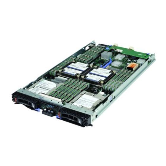
BladeCenter HX5 Blade Server
Installation and User's Guide
Machine Types: 7873, 7872, 1910, 1909
Table of
Contents
Previous
Page
Next
Page
1
2
3
4
5
Advertisement
Table of Contents
Need help?
Do you have a question about the BladeCenter HX5 and is the answer not in the manual?
Ask a question
Questions and answers
Related Manuals for Lenovo BladeCenter HX5
Server Lenovo HX3510-G Installation And Service Manual
Converged hx series server (1240 pages)
Server Lenovo HX5510 Installation And Service Manual
Converged hx series server (1240 pages)
Server Lenovo HX1310 Installation And Service Manual
Converged systems converged hx series (1002 pages)
Server Lenovo HX3310 Installation And Service Manual
Converged systems converged hx series (1002 pages)
Server Lenovo ThinkAgile HX1320 Product Manual
Thinkagile hx series (32 pages)
Server Lenovo ThinkAgile HX2320-E Product Manual
(33 pages)
Server Lenovo ThinkAgile HX5521 User Manual
(106 pages)
Server Lenovo ThinkAgile HX1521-R User Manual
(106 pages)
Server Lenovo ThinkAgile HX7521 User Manual
(106 pages)
Server Lenovo ThinkAgile HX3320 Hardware Replacement Manual
1u models (26 pages)
Server Lenovo ThinkAgile HX1321 Series User Manual
Node (104 pages)
Server Lenovo ThinkAgile HX3321 Series User Manual
Node (104 pages)
Server Lenovo ThinkAgile HX2320 Appliance User Manual
(100 pages)
Server Lenovo ThinkAgile HX2321 Certified Node User Manual
(100 pages)
Server Lenovo Converged HX3710 Installation And Service Manual
(246 pages)
Server Lenovo Converged HX Series Installation And Service Manual
(246 pages)
This manual is also suitable for:
7873
7872
1910
1909
Table of Contents
Save PDF
Print
Rename the bookmark
Delete bookmark?
Delete from my manuals?
Login
Sign In
OR
Sign in with Facebook
Sign in with Google
Upload manual
Upload from disk
Upload from URL


Need help?
Do you have a question about the BladeCenter HX5 and is the answer not in the manual?
Questions and answers