Chapters
Table of Contents

Related Manuals for BK Precision 0-30V


Summary of Contents for BK Precision 0-30V
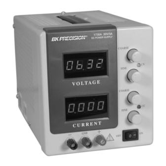
- Page 1 INSTRUCTION MODEL 1735A MANUAL MODELO 1735A El Manual de la Instrucción Manual de Instruccion 0-30V, 0-3A DC POWER SUPPLY With Dual 4-Digit LED Displays Fuente de poder DC Con doble LED indicador...
-
Page 2: Test Instrument Safety
If the equipment under test is “powered up” (and that equipment uses high voltage in any of its circuits), the power supply outputs may be floated to the potential at the point of connection. Remember that high voltage may appear at unexpected points in defective equipment. - Page 3 Instruction Manual Model 1735A 0-30 V, 0-3 A DC POWER SUPPLY With Dual LED Display 22820 Savi Ranch Parkway Yorba Linda, CA 92887 www.bkprecision.com...
-
Page 4: Table Of Contents
TEST INSTRUMENT SAFETY ----------------inside front cover INTRODUCTION------------------------------------------------------ 5 FEATURES ------------------------------------------------------------- 6 SPECIFICATIONS ---------------------------------------------------- 7 CONTROLS AND INDICATORS---------------------------------- 9 OPERATING INSTRUCTIONS ---------------------------------- 11 Safety Precautions--------------------------------------------------11 Equipment Precautions --------------------------------------------11 Hook-Up -------------------------------------------------------------11 Typical Constant Voltage Operation -------------------------- 14 Setting Current Limit ----------------------------------------------15 Typical Constant Current Operation --------------------------- 16 Constant Voltage/Constant Current Characteristic ----------17 Connecting Two Power Supplies in Series ------------------- 17 Connecting Two Power Supplies in Parallel ------------------20... -
Page 5: Introduction
The B+K Precision Model 1735A DC Power Supply is a high quality, general purpose dc power source. It provides 0-30 volts dc output, adjustable with both coarse and fine voltage controls for precise settability. The current output is 0-3 amps, adjustable with both coarse and fine current controls. -
Page 6: Features
Fully adjustable current limiting (from 5% to 100% of maximum output current) protects circuit under test and the power supply. REVERSE POLARITY PROTECTION Prevents damage to power supply from external voltage of reverse polarity. STYLING Modern functional styling. Configuration conserves bench space and aids portability. -
Page 7: Specifications
OUTPUT VOLTAGE: 0 to 30VDC, coarse and fine adjustment. OUTPUT CURRENT: 0 to 3A, coarse and fine adjustment. CONSTANT VOLTAGE OPERATION Voltage Regulation Line (108-132 V): 0.01% + 3mV. Load (no load to full load): 0.01% + 3mV. Recovery Time: 100 µs typical. -
Page 8: Temperature Range
Thermal Drift: Since this power supply has greater resolution than standard bench power supplies they are more susceptible to Thermal Drift. Thermal Drift occurs on almost every type of power supply but is more apparent on high resolution types. Thermal Drift results in the metering of the power supply to either slowly increase or decrease with the change in the power supply’s internal temperature. -
Page 9: Controls And Indicators
INDICATORS Either the “CC” or “CV” and the LED indicators will be lit whenever the unit is operating, thus serving as a pilot light. The unit automatically changes from CV to CC operation when the preset current limit is reached. 1. -
Page 10: Rear Panel Controls
CONTROLS AND INDICATORS REAR PANEL CONTROLS 13. Fuse. 14. Power Cord. 15. 110/220 Line Voltage Conversion Switch. Figure 1. Front Panel Controls and Indicators. Figure 2. Rear Panel... -
Page 11: Operating Instructions
(referenced to a voltage rather than earth ground) turn off the power supply and the equipment under test when making connections. Never float the power supply to a potential greater than 100 volts peak with respect to earth ground. EQUIPMENT PRECAUTIONS Avoid using the power supply in ambient temperatures above +40°... - Page 12 OPERATING INSTRUCTIONS Equipment Equipment Being Powered Being Powered Strap Strap Grounded, common with Grounded, common with positive polarity negative polarity Figure 3 (A and B). Grounding Possibilities.
- Page 13 Strap No ground reference Figure 3 (C and D). Grounding Possibilities. Equipment Being Powered Strap Grounded, not common with Negative or positive polarity. OPERATING INSTRUCTIONS Equipment Being Powered...
-
Page 14: Typical Constant Voltage Operation
2. Set Fine VOLTAGE control to center and Coarse VOLTAGE control to minimum (fully counterclockwise). 3. Turn off power supply and connect it to the device to be powered (see “Hook-Up” procedure in this section). 4. Turn on POWER switch. The C V indicator should light. -
Page 15: Setting Current Limit
7. If the load current exceeds the preset current limit, the CV indicator will go off and the CC indicator will light. In this case, the power supply automatically switches to the constant current mode, and further rotation of the VOLTAGE control will not increase the output voltage. -
Page 16: Typical Constant Current Operation
2. Determine the desired constant current value. 3. Set the Coarse and Fine CURRENT control to minimum (fully counterclockwise). 4. Turn off the power supply and connect it to the device to be powered. 5. Turn on the power supply. The CC indicator should light. -
Page 17: Constant Voltage/Constant Current Characteristic
Fig. 7 shows the relationship between this crossover point and the load. For example, if the load is such that the power supply is operating in the constant voltage mode, a regulated output voltage is provided. The output voltage remains constant as the load increases, up until the point where the preset current limit is reached. - Page 18 OPERATING INSTRUCTIONS Output voltage equals sum of both displays “in voltage metering mode” Output current equals value on either ammeter (both read identical) Load Figure 8. Connecting Two Power Supplies in Series.
- Page 19 Output current equals sum of both displays Figure 9. Connecting Two Power Supplies in Parallel. OPERATING INSTRUCTIONS Adjust both power supplies to same voltage Use load equalizing resisters Load...
-
Page 20: Connecting Two Power Supplies In Parallel
When connected in parallel and operating in the constant voltage mode, determine the total load current limit and preset the current limiting for each power supply to half the total load current value. Then when the load is connected, set the VOLTAGE controls on the two power supplies for equal voltage readings. -
Page 21: Applications
ELECTRONICS SERVICING Most electronics troubleshooting and repair is performed on a test bench. This power supply can provide the dc power source to operate a module or circuit board on the test bench when it is removed from its parent equipment. It can be used to power portable, battery -operated equipment and check the effect of low battery voltage. -
Page 22: Electronics Design Lab
BATTERY CHARGING The power supply can be used as a battery charger to restore the charge in rechargeable batteries such as lead-acid, nickel-cadmium, and some alkaline types. Refer to the battery manufacturer’s charging specifica tions for proper... -
Page 23: Fuse Replacement
FUSE REPLACEMENT If the fuse blows, the CV or CC indicators will not light and the power supply will not operate. The fuse should not normally open unless a problem has developed in the unit. Try to determine and correct the cause of the blown fuse, then replace only with a fuse of the correct rating as listed below. -
Page 24: 1735A Calibration
MAINTENANCE 1735A CALIBRATION If readjustment is required, use the following procedure. Locations of the adjustments are shown in Fig. 11. 1. Set the front panel controls of the Model 1735A as follows: Coarse and Fine VOLTAGE controls fully clockwise. Coarse and Fine CURRENT controls fully clockwise. - Page 25 MAINTENANCE Figure 11. Location of Adjustments.
- Page 26 NOTES...
-
Page 27: Warranty Service Instructions
Service Information Warranty Service: Please return the product in the original packaging with proof of purchase to the address below. Clearly state in writing the performance problem and return any leads, probes, connectors and accessories that you are using with the device. Non-Warranty Service: Return the product in the original packaging to the address below. -
Page 28: Limited Two-Year Warranty
Limited Two-Year Warranty B&K Precision Corp. warrants to the original purchaser that its products and the component parts thereof, will be free from defects in workmanship and materials for a period of two years from date of purchase. B&K Precision Corp. will, without charge, repair or replace, at its option, defective product or component parts. Returned product must be accompanied by proof of the purchase date in the form of a sales receipt. - Page 29 4. If possible, familiarize yourself with the equipment being tested and the location of its high voltage points. However, remember that high voltage may appear at unexpected points in defective equipment. 5. Use an insulated floor material or a large, insulated floor mat to stand on, and an insulated work surface on which to place equipment;...
-
Page 30: Spanish Manual
SEGURIDAD DE EL INSTRUMENTO DE PRUEBA Uso normal de probado de prueba te espose a cierta cantidad de peligro por un choque eléctrico porque revisiones son algunas veces hechas donde hay alto voltaje descubierto. Un choque eléctrico que cause 10 milliamps pasar a través del corazón pararía la mayoría de los corazones humanos. - Page 31 Manual de instrucciones Modelo 1735A Fuente de poder DC Con doble LED indicador...
- Page 32 SEGURIDAD DE EQUIPO DE PRUEBA INTRODUCCION...33 CARACTERISTICAS...34 ESPECIFICACIONES...35 CONTROLES & INDICADORES...37 INTRODUCIONES DE OPERACIÓN...39 precauciones de segundad ...39 precauciones del equipo...39 Conexión ... Típica operación de voltaje constante...42 Estableciendo el limite de corriente...43 Típica operación de corriente constante...44 Voltaje constante / corriente constante Características ...45 Conectando dos fuentes de poder en series ...45 TABLA DE CONTENDIDO...
-
Page 33: Introduccion
INTRODUCCION El B & K Precision Modelo 1735 CD Fuente de Poder es de una alta calidad, propósito general cd fuente de poder. Provee 0 –30 voltios cd salida, ajustable con ambos grueso y fino controles de voltaje para precisos ajustes. La salida de corriente es 0-3 amperios, ajustable grueso y fino controles de corriente. -
Page 34: Caracteristicas
0-30 VOTIOS Continuamente variable sobre 0 a 30 voltios rango con grueso y fino controles 0-3 AMPERIOS 0 a 3 amps corriente probada para continuo servido al la completa salida de corriente . Grueso y fino controles de ajuste de corriente CALIDAD DE LABORATORIO Excelente regulacio,baja onduracio VOLTAJE CONSTANTE O CORRIETE CONSTANTE... -
Page 35: Especificaciones
VOLTAJE DE SALIDA: 0 a 30VDC grueso y fino ajuste CORRIENTE DE SALIDA: 0 a 3A grueso y fino ajuste OPERACIÓN DE CONSTANTE VOLTAJE Regulación de voltaje Línea (108-132V): Carga (no carga a carga completa):0.01% + 3 mv Tiampo de reoperación: Voltaje deondulación Pico a pico: RMS:... - Page 36 ESPECIFICACIONES RANGO DE TEMPERATURA Operación: 0° a +40°C, 75%R.H Almacenamiento: -15° a +70°C, 85% R,H DIMENSIONES (AxAxP): 6.2x5.5x12.5” PESO: 10.5 LB ACCESORIOS INCLUIDOS : Fusible extra, Manual de instrucciones NOTA: Las especificaciones y la información están conforme a cambio sin el aviso de B&K Precision Corp. Por favor visite www.bkprecision.com para las especificaciones más corriente y información de nuestros productos.
-
Page 37: Controles & Indicadores
INDICADORES Sea el “CC” o “CV” y los LED indicadores pueden ser prendidos cuando sea que la unidad este operando, de este modo sirviendo como una luz piloto. La unidad automáticamente cambia de CV a CC operación cuando el preseleccionado limite de corriente es alcanzado. -
Page 38: Controles E Indicadores
CONTROLES E INDICADORES Figura 1.Controles e indicadores de el panel delantero CONTROLES DEL PANEL TRASERO 13. Fusible 14. Cordón de poder Figura 2.Panel trasero... -
Page 39: Introduciones De Operación
PRECAUCIONES DE SEGURIDAD Use solo a polarizado 3 -conductores ca enchufe. Esto asegure que la fuente de poder chasis, caja, y la terminal de tierra son conectada a una buena tierra y reduce el peligro de un choque eléctrico. Hay un pequeño peligro de choque eléctrico dela salida de la fuente de poder, cual produce un máximo de 30 voltios cd. -
Page 40: Instrucciones De Operación
INSTRUCCIONES DE OPERACIÓN Equipo encendido Equipo encendido Corto Corto Tierra,comun con Tierra,comun con Polaridad negativas polaridad positiva Figura A y B .Posibilidades de conecciones etierra... - Page 41 INSTRUCCIONES DE OPERACIÓN Equipo encendido Equipo encendido Corto Corto No referencia a tierra A tierra,no comun con Polaridades Negativas o positivas Figura 3 (C y D)
-
Page 42: Típica Operación De Voltaje Constante
INSTRUCCIONES DE OPERACIÓN Si la referencia de tierra no es requerida, la configuración de Fig. 3C puede ser usada. El diagrama in Fig.3C debería también ser usado donde no es conocido si el chasis es común con la polaridad positiva o negativa. el chasis o común de el equipo encendido es separado de ambas polaridades negativa y positiva entradas de poder, use la conexión en Fig. -
Page 43: Estableciendo El Limite De Corriente
INSTRUCCIONES DE OPERACIÓN xAumente la posición de el VOLTAJE hasta que la Voltaje LED pantalla lea el valor deseado. El control FINO permite mas fácil colocación a un valor especifico. 6. Note la carga de la corriente en la Corriente LED pantalla. 7. -
Page 44: Típica Operación De Corriente Constante
OPERACION TIPICA DE CORRIENTE CONSTANTE 1. Antes de conectar el dispositivo que va ha ser encendido por la fuente de poder, determine el voltaje máximo seguro que va ha ser aplicado, y coloque los controles de VOLTAJE obtener esa lectura de voltaje en la Voltaje LED pantalla. 2. -
Page 45: Voltaje Constante/ Corriente Constante
VOLTAJE CONSTANTE/ CORRIENTE CONSTANTE CARACTERISTICAS La característica de trabajo de esta fuente de poder es llamada un constante voltaje/ constante corriente automático cruce tipo. Esto permite continua transición de constante corriente a constante voltaje modo en respuesta al cambio de carga. La intersección de constante voltaje y constante corriente modos es llamada él punte de cruce. - Page 46 Voltaje de salida es igual a la suma de ambas pantallas Lea la corriente de cualquier Los dos lean idénticamente Carga Figura 8 .Conectando dos fuentes de poder en serie...
- Page 47 salida de corriente es igual a la suma de las dos pantallas 0.1? 0.1? Figura 9. Conectando dos fuentes de poder en paralelo Ajuste ambas fuentes de poder a el mismo voltaje Uso de resistores igualadores Carga...
-
Page 48: Conectando Dos Fuentes De Poder En Paralelo
CONECTANDO DOS FUENTES DE PODER EN PARALELO Dos fuentes de poder pueden ser conectadas en paralelo para doblar la corriente máxima de corriente. En esta configuración las dos fuentes proveerán dos 0-30 voltios salida hasta 6 amps (mas grueso de sondas es recomendable). Resistor igualador de corriente debe de ser usados como se muestra en la Fig. -
Page 49: Aplicaciones
GENERAL El modelo 1735A fuente de poder tiene una muy ancha variedad de aplicaciones en el servicio eléctrico y electrónico, laboratorios de ingeniería, manufactura y lugares de prueba, escuelas, para el aficionado. La salida de la fuente de poder es totalmente ajustable desde 0 a 30 voltios y de 0 a 3 amps. -
Page 50: Laboratorio De Diseño Electrónico
LABORATORIO DE DISENO ELECTRONICO El técnico o el ingeniero trabajando en un laboratorio de ingeniería recrié de una fuente de energía cd para prender tableros y circuitos. Esta fuente de poder es ideal porque ve la corriente de salida, el volare de salida, limita la corriente para proteger el circuito, y es ajustable sobre un ancho rango, además tiene excelente regulación y muy baja ondulación. -
Page 51: Mantenimiento
PRECAUCION Las siguientes instrucciones son solo para el uso de personal calificado. Para evitar choque eléctrico, no haga ningún servicio otro que el contenido en las instrucciones de operación al menos que este calificado para hacerlo. REMPLAZO DE FUSIBLE Si el fusible se quema, la CV,CC o LED medidores indicadores se encenderán y la fuente de energía no funcionara. -
Page 52: Calibración
1735A CALIBRACION Si ajustes son requeridos, use el siguiente procedimiento. Lugares de ajuste son mostrados en Fig. 11. Ponga el panel delantero de controles de el Modelo 1735 como sigue: Grueso y Fino VOLTAJE controles completamente en la dirección de la anejillas del reloj Grueso y Fino CORRIENTE controles completamente en la dirección de las manejillad del reloj Switch de poder en encendido... -
Page 54: Information De Servicio
INFORMACION DE SERVICIO Servicio de Garantía: Por favor regrese el producto en el empaquetado original con prueba de la fecha de la compra a la dirección debajo. Indique claramente el problema en escritura, incluya todos los accesorios que se estan usado con el equipo. Servicio de No Garantía: Por favor regrese el producto en el empaquetado original con prueba de la fecha de la compra a la dirección debajo. -
Page 55: Dos-Anos De Garantia Limitada
DOS-ANOS DE GARANTIA LIMITADA B&K Precision Corp. Autorizaciones al comprador original que su productos y componentes serán libre de defectos por el periodo de dos anos desde el día en que se compro. B&K Precision Corp. sin carga, repararemos o sustituir, a nuestra opción, producto defectivo o componentes. Producto devuelto tiene que ser acompañado con prueba de la fecha del la compra en la forma de un recibo de las ventas. - Page 56 Si es posible, familiarícese con el equipo que va ha ser revisado y el lugar de los puntos de alto voltaje. Pero, recure que alto voltaje puede aparecer en puntos inesperados en equipo defectivo Use un piso de material insuflado o un largo, insuflado tapete para parase en el, y una superficie de trabajo insuflada el la cual pueda poner el equipo;...
- Page 57 Responsible Party B&K Precision Corporation Manufacturer’s Name: 22820 Savi Ranch Pkwy. Manufacture’s Address: Yorba Linda, CA 92887-4610 Declares that the below mentioned product DC Power Supplies Product Name: 1651A, 1652, 1653A, 1655A, 1710A, 1711A, 1715A, 1730A, 1735A, 1740A, 1740B, 1743A, 1744, 1745, Part Numbers: 1745A, 1746A, 1760A, 1761 complies with the essential requirements of the following applicable European Directives:...
- Page 58 22820 Savi Ranch Parkway Yorba Linda, CA 92887 www.bkprecision.com © 2005 B&K Precision Corp. 481-395-9-001 Printed in Taiwan...
Need help?
Do you have a question about the 0-30V and is the answer not in the manual?
Questions and answers