Sign In
Upload
Download
Table of Contents
Contents
Add to my manuals
Delete from my manuals
Share
URL of this page:
HTML Link:
Bookmark this page
Add
Manual will be automatically added to "My Manuals"
Print this page
×
Bookmark added
×
Added to my manuals
Manuals
Brands
BK Precision Manuals
Power Supply
1760A
Instruction manual
BK Precision 1760A Instruction Manual
Triple output dc power supply with dual 4digit led displays
Hide thumbs
1
2
3
Table Of Contents
4
5
6
7
8
9
10
11
12
13
14
15
16
17
18
19
20
21
22
23
24
25
26
27
28
29
30
31
32
33
34
35
36
37
38
39
40
41
42
43
44
45
46
47
48
49
50
page
of
50
Go
/
50
Contents
Table of Contents
Bookmarks
Table of Contents
Test Instrument Safety
Table of Contents
Introduction
Features
Specifications
Controls and Indicators
General Controls and Indicators
4-6.5 V Supply Controls and Indicators
A" Supply Controls and Indicators
B" Supply Controls and Indicators
Rear Panel Controls
Independent Use of "A" or "B" Supply
Operating Instructions
Safety Precautions
Equipment Precautions
Hook-Up
Typical Constant Voltage Operation
Setting Current Limit
Typical Constant Current Operation
Constant Voltage/Current Characteristic
Series Tracking Operation
Parallel Tracking Operation
4-6.5 V Power Supply Operation
Application
General
Electronics Servicing
Electronics Manufacturing
Electronics Design Lab
Electronics Education
Battery Charging
Split Supply
Maintenance
Fuse Replacement
Line Voltage Conversion
A" Supply and "A" Metering Adjustments
Adjustments
B" Supply and Metering Adjustments
4-6.5 V Supply and 6.5 V Metering Adjustments
B" Series Tracking Adjustment
Instrument Repair Service
Warranty Service Instructions
Limited Two-Year Warranty
Advertisement
Quick Links
1
Specifications
2
Operating Instructions
Download this manual
INSTRUCTION
MANUAL
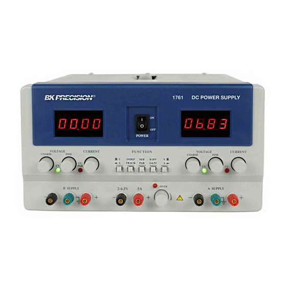
MODELS: 1760A, 1761, 1762
Triple Output
DC POWER SUPPLY
With Dual 4-Digit LED Displays
Table of
Contents
Previous
Page
Next
Page
1
2
3
4
5
Advertisement
Table of Contents
Need help?
Do you have a question about the 1760A and is the answer not in the manual?
Ask a question
Questions and answers
Related Manuals for BK Precision 1760A
Power Supply BK Precision 1761 Instruction Manual
Triple output dc power supply with dual 4digit led displays (50 pages)
Power Supply BK Precision 1762 Instruction Manual
Triple output dc power supply with dual 4digit led displays (50 pages)
Power Supply BK Precision 1794 Instruction Manual
B&k instruction manual high current power supply 1794 (42 pages)
Power Supply BK Precision 1785B Instruction Manual
B&k precision programmable dc power supplies instruction manual (38 pages)
Power Supply BK Precision 1785B Instruction Manual
Programmable dc power supplies (38 pages)
Power Supply BK Precision 1785B Instruction Manual
B&k precision programmable dc power supplies instruction manual (38 pages)
Power Supply BK Precision 1739 Instruction Manual
Dc power supply with 0.1ma settable resolution (36 pages)
Power Supply BK Precision 1743B Instruction Manual
0-35v, 0-6a dc power suply with dual 4-digit led display (27 pages)
Power Supply BK Precision 1743B Instruction Manual
0-35 v, 0-6 a dc power supply with dual 4-digit led displays (28 pages)
Power Supply BK Precision 1737 Instruction Manual
Dual range dc power supply (31 pages)
Power Supply BK Precision 1790 Operation & Maintenance Manual
High current power supply (48 pages)
Power Supply BK Precision 0-30V Instruction Manual
0-30v, 0-3a dc power supply with dual 4-digit led displays (58 pages)
Power Supply BK Precision 1715A Instruction Manual
0-60v, 0-2a. with dual led display (25 pages)
Power Supply BK Precision 1744A Instruction Manual
0-35 v, 0-10 a dc power supply with dual displays (28 pages)
Power Supply BK Precision 1710 Instruction Manual
0-30 v dc power supply 0-1a (1710) 0-3a (1730) (27 pages)
Power Supply BK Precision 1730 Instruction Manual
0-30 v dc power supply 0-1a (1710) 0-3a (1730) (27 pages)
This manual is also suitable for:
1761
1762
Table of Contents
Print
Rename the bookmark
Delete bookmark?
Delete from my manuals?
Login
Sign In
OR
Sign in with Facebook
Sign in with Google
Upload manual
Upload from disk
Upload from URL


Need help?
Do you have a question about the 1760A and is the answer not in the manual?
Questions and answers