Icom IC-FR6000-L Instruction Manual
Vhf fm repeater, uhf fm repeater
Hide thumbs
Also See for IC-FR6000-L:
- Instruction manual (16 pages) ,
- Service manual addendum (341 pages)
Table of Contents
Advertisement
Quick Links
Advertisement
Table of Contents

Related Manuals for Icom IC-FR6000-L


Summary of Contents for Icom IC-FR6000-L
- Page 1 INSTRUCTION MANUAL VHF FM REPEATER iFR5000 UHF FM REPEATER iFR6000 iFR6000-L...
-
Page 2: Important
IMPORTANT Thank you for choosing this Icom product. This product is designed and built with Icom’ s state of the art technology and craftsmanship. With proper READ THIS INSTRUCTION MANUAL care, this product should provide you with years of CAREFULLY before attempting to operate the re- trouble-free operation. -
Page 3: Table Of Contents
NEVER leave the transceiver in an insecure place to avoid use by unauthorized persons. For U.S.A. only CAUTION: Changes or modifications to this repeater, not expressly approved by Icom Inc., could void your authority to operate this repeater under FCC regula- tions. -
Page 4: Safety Training Information
Electromagnetic Interference/Compatibility ficient distance from a properly installed external- During transmissions, your Icom radio generates RF ly-mounted antenna to satisfy the RF exposure energy that can possibly cause interference with other requirements in the applicable RF exposure com- devices or systems. - Page 5 Interférence électromagnétique et compatibilité Cette distance de sécurité assurera que les per- sonnes soient placées suffisamment loin d’une En mode de transmission, votre radio Icom produit de antenne correctement fixée à l’extérieur pour sat- l’énergie de RF qui peut provoquer des interférences isfaire aux exigences en matière d’exposition aux...
-
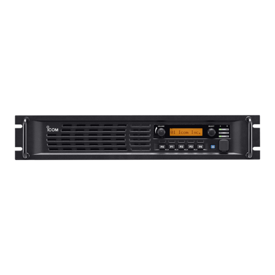
Page 6: Panel Description
PANEL DESCRIPTION n Front panel Function display q INTERNAL SPEAKER u MICROPHONE CONNECTOR [MIC] Outputs the received audio. This 8-pin modular jack accepts an optional micro- phone. w VOLUME CONTROL [VOLUME] (p. 7) KEEP the [MIC] connector cover attached to the Adjusts the audio output level. -
Page 7: D Function Display
PANEL DESCRIPTION D Function display I C O M I n c . q SIGNAL STRENGTH INDICATOR r COMPANDER INDICATOR Indicates relative signal strength level. Appears when the compander function is activated. w LOW POWER INDICATOR t SCRAMBLER/ENCRYPTION INDICATOR Appears when low output power is selected. Appears when the voice scrambler/encryption function is activated. -
Page 8: D Accessory Connector
PANEL DESCRIPTION D Accessory connector Pin No. Pin Name Description Specification No connection — Output terminal for serial communication data. — Input terminal for serial communication data. — Output terminal for request-to-send data. — Input terminal for clear-to-send data. — No connection —... -
Page 9: Installation And Connections
INSTALLATION AND CONNECTIONS n Unpacking n Antenna connection After unpacking, immediately report any damage to For radio communications, the antenna is a critical the delivering carrier or dealer. Keep the shipping car- component, along with output power and sensitivity. tons. Select antenna(s), such as a well-matched 50 ø... -
Page 10: Front Panel Connection
Input port for PC programming CAUTION: DO NOT short pin 1 to ground as this can damage the internal 8 V regulator. DC voltage is applied to pin 1 for microphone operation. Only Icom micro- phones are recommended. n Rear panel connection... -
Page 11: Power Supply Connection
INSTALLATION AND CONNECTIONS n Power supply connection n Mounting the repeater D Using the supplied handles Make sure the repeater’s power is turned OFF when connecting a DC power cable. The supplied handles are used when mounting the re- peater into a 19 inch rack. The handles are installed on R WARNING! NEVER apply more than 16 V DC to the repeater’s front panel. -
Page 12: Operation
OPERATION n Receiving and transmitting D Base station operation D Repeater operation Receiving Ask your dealer for details of the repeater’s preset- q Push [POWER] to turn ON the power. tings. w Set the audio and squelch levels. ➥ Rotate [SELECT]* fully counterclockwise in ad- ➥ W hen the power is turned ON, the [PWR] indicator vance. -
Page 13: Maintenance
If you are unable to locate the cause of a problem The following chart is designed to help you correct or solve it through the use of this chart, contact your problems that are not equipment malfunctions. nearest Icom Dealer or Service Center. PROBLEM POSSIBLE CAUSE SOLUTION REF. -
Page 14: Options
OPTIONS • SP-35 external speaker Compact and easy-to-install. Input impedance: 4 ø Rated input: 5 W Maximum input: 7 W • HM-152 hand microphone • SM-26 desktop microphone • UR-FR5000/UR-FR6000 channel extension modules • UC-FR5000 trunking network controller • UT-109R voice scrambler unit Non-rolling type (32 codes maximum). -
Page 15: Information
INFORMATION • ABOUT VOICE CODING TECHNOLOGY The AMBE+2™ voice coding Technology embodied in this product is protected by intellectual property rights including patent rights, copyrights and trade secrets of Digital Voice Systems, Inc. This voice coding Tech- nology is licensed solely for use within this Communi- cations Equipment. - Page 16 A6635H-1EX-9a Printed in Japan © 2007–2018 Icom Inc. 1-1-32 Kamiminami, Hirano-ku, Osaka 547-0003, Japan Printed on recycle paper with soy ink.
Need help?
Do you have a question about the IC-FR6000-L and is the answer not in the manual?
Questions and answers