Ruijie RG-S6250-48XS8CQ Hardware Installation And Reference Manual
Hide thumbs
Also See for RG-S6250-48XS8CQ:
- Hardware installation and reference manual (47 pages) ,
- Hardware installation (55 pages)

Subscribe to Our Youtube Channel
Related Manuals for Ruijie RG-S6250-48XS8CQ


Summary of Contents for Ruijie RG-S6250-48XS8CQ
- Page 1 Ruijie RG-S6250-48XS8CQ Switch Hardware Installation and Reference Guide Document Version: V2.0 Date: August 15, 2023 Copyright © 2023 Ruijie Networks...
- Page 2 Due to product version upgrades or other reasons, the content of this document will be updated from time to time. Ruijie Networks reserves the right to modify the content of the document without any notice or prompt. This manual is for reference only. Ruijie Networks endeavors to ensure content accuracy and will not shoulder any responsibility for losses and damages caused due to content omissions, inaccuracies or errors.
-
Page 3: Preface
Preface Intended Audience This document is intended for: Network engineers Technical support and servicing engineers Network administrators Technical Support Ruijie Networks website: https://www.ruijienetworks.com/ Technical support website: https://ruijienetworks.com/support Case portal: https://caseportal.ruijienetworks.com Community: https://community.ruijienetworks.com ... - Page 4 Specification An alert that contains a description of product or version support. 2. Note The manual offers configuration information (including model, port type and command line interface) for indicative purpose only. In case of any discrepancy or inconsistency between the manual and the actual version, the actual version prevails.
-
Page 5: Table Of Contents
Contents Preface ..............................I 1 Overview ............................1 1.1 About the RG-S6250-48XS8CQ ....................1 1.2 Component Modules ........................1 1.3 Chassis ............................2 1.3.1 Appearance ........................2 1.3.2 LEDs ..........................4 1.3.3 Ports ..........................5 1.3.4 Cooling ........................... 7 1.3.5 Technical Specifications ....................8 1.3.6 Nameplate ........................ - Page 6 1.7 Pluggable Modules ........................29 2 Preparing for Installation ......................... 31 2.1 Safety Guidelines ........................31 2.1.1 General Precautions ....................31 2.1.2 Chassis-Lifting Guidelines ................... 31 2.1.3 Electricity Safety ......................32 2.1.4 Preventing ESD Damage ..................... 32 2.1.5 Laser Safety ......................... 33 2.1.6 Storage Guidelines ......................
- Page 7 3 Installing the Switch ........................41 3.1 Installation Procedure ......................41 3.2 Installing the Rack........................42 3.2.1 Installation Guidelines ....................42 3.2.2 Procedure ........................43 3.3 Installing the Chassis ....................... 43 3.3.1 Installation Guidelines ....................43 3.3.2 Mounting the Brackets ....................43 3.3.3 Mounting the Chassis on the Rack ................
- Page 8 4 Commissioning ..........................56 4.1 Setting Up the Configuration Environment ................56 4.2 Powering on the Device ......................58 4.2.1 Checklist Before Power-on ..................58 4.2.2 Power-on ........................58 4.2.3 Checklist Before Power-on ..................58 5 Monitoring and Maintenance ......................59 5.1 Monitoring ..........................
- Page 9 7 Appendix ............................64 7.1 Labeling Process ........................64 7.1.1 Hand Writing on Labels ....................64 7.1.2 Pasting Labels ......................65 7.1.3 Label Contents ......................66 7.2 Connectors and Media ......................66 7.2.1 10GBASE-T Port ......................66 7.2.2 1000BASE-T Port ......................68 7.2.3 100BASE-TX/10BASE-T Port ..................
-
Page 10: Overview
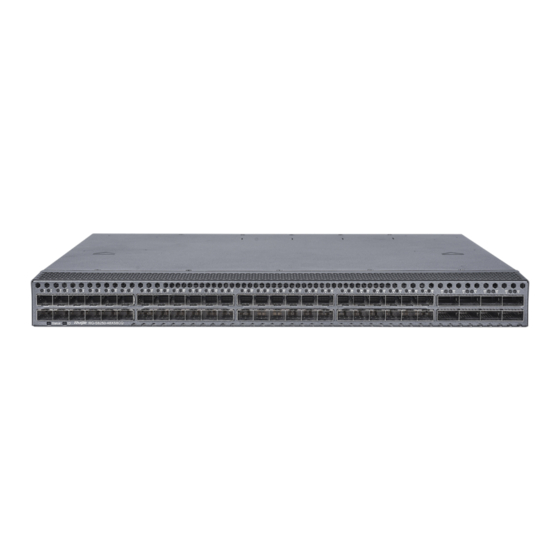
Ruijie Networks for data centers and high-end campuses. The RG-S6250-48XS8CQ switch provides high-density 10GE access, 100GE uplink ports, and diverse data center features. It can be used with Ruijie’s RG-N18000- X and RG-S6920-4C switches for a high-performance and high-reliability data center network. -
Page 11: Chassis
For example, input 1 uses mains electricity (AC power) and input 2 use Uninterrupted Power Supply (UPS) DC power. Chassis The RG-S6250-48XS8CQ hardware system consists of a chassis, a power supply system, and a cooling system. Power supply system: provides two power module slots and supports 1+1 power redundancy. - Page 12 Hardware Installation and Reference Guide Overview 2. Structure Figure 1-3 Front Panel Structure Table 1-3 Front Panel Components Component Status LED Locating LED SFP28+ port SFP28+ port LED QSFP28 port QSFP28 port LED Figure 1-4 Rear Panel Structure Table 1-4 Rear Panel Components Component Power module slot Fan module slot...
-
Page 13: Leds
Hardware Installation and Reference Guide Overview Component Locating LED Management port USB port Grounding stud Asset tag Status LED Console port 1.3.2 LEDs Table 1-5 LEDs Silkscreen Description Label Solid green: The system is operating normally. Blinking green: The system is starting up. Solid red: ○... -
Page 14: Ports
Hardware Installation and Reference Guide Overview Silkscreen Description Label Solid green: The port has made a successful link. QSFP28 port 49F to 56F Blinking green: The port is sending and receiving traffic. Off: No link is detected for the port. Solid yellow: The port has made a successful 10/100 Mbps link. - Page 15 Hardware Installation and Reference Guide Overview Port Connector Type Description Accessory transmission. module Standards compliance: IEEE802.3ba Working mode: Full- duplex Optical attributes: Subject to the module or cable The management port is used to set up the onsite or remote configuration environment.
-
Page 16: Cooling
○ Default value: 9,600 bit/s 1.3.4 Cooling 1. Overview The RG-S6250-48XS8CQ adopts the front-to-rear airflow. Air flows in through the ports and out through the power module, as shown in Figure 1-5. Caution Maintain a minimum clearance of 200 mm (7.87 in.) around the equipment for air circulation. -
Page 17: Technical Specifications
Hardware Installation and Reference Guide Overview 1.3.5 Technical Specifications Table 1-7 Technical Specifications Class Item Specification 1.2 GHz quad-core Memory 4 GB, DDR4 (compatible with 8 GB) Technical indicators NOR flash: MB (for BootROM) Flash memory NAND flash: 8 GB Without packing materials: 442 mm x 387 mm x 44 Dimensions mm (17.40 in. - Page 18 Hardware Installation and Reference Guide Overview Class Item Specification Operating altitude: 0–5,000 m (16,404.20 ft.) Altitude Storage altitude: 0–5,000 m (16,404.20 ft.) Operating temperature: 0° C to 40° C (32° F to 104° F) at an altitude in the range of 0–2,000 m (0–6,561.68 ft.) Note Temperature...
- Page 19 Hardware Installation and Reference Guide Overview Class Item Specification HVDC: 160 V DC to 400 V DC RG-PA550I-F: Rated voltage: 110 V AC/220 V AC Rated voltage range: 100 V AC to 120 V AC/ 200 V AC input AC to 240 V AC (50 Hz to 60 Hz) Max.
- Page 20 Hardware Installation and Reference Guide Overview Class Item Specification power module panel) Cooling mode Fan cooling Cooling Fan type Swappable fan Mean Time Between 38.5 years Failure (MTBF) Mean Time to Recovery 0.5 hours (MTTR) Reliability Availability 0.9999985 Power redundancy redundancy Hot swapping Hot swappable power and fan modules...
-
Page 21: Nameplate
Hardware Installation and Reference Guide Overview 1.3.6 Nameplate The nameplate is at the bottom of the chassis, as shown in Figure 1-6. The equipment is no more than 18 kg (39.68 lbs.) in weight. Figure 1-6 Nameplate Location 1.3.7 Asset Tag The asset tag is in the lower right corner of the rear panel. -
Page 22: Power Modules
Hardware Installation and Reference Guide Overview Power Modules The smart power modules for the RG-S6250-48XS8CQ support power consumption management and hot swapping. They can obtain the output power, output current, and operating temperature in real time. Caution To improve system stability and availability, you are advised to configure 1+1 power redundancy. - Page 23 Hardware Installation and Reference Guide Overview Figure 1-9 Structure Table 1-8 Components Component Description Handle Handle of the power module Forward fan Power Three-pin connector connector Power status LED Latch Latch of the power module 2. LED Table 1-9 Silkscreen Description Label Solid green: The power module is outputting power normally.
- Page 24 Hardware Installation and Reference Guide Overview outputting power. Solid red: ○ The power module is not functioning properly (overcurrent, overvoltage, or fan failure). ○ The power module in redundancy mode is removed. Blinking red at 1 Hz: The power module is operating but with alarms, such as high power, high current, high temperature, and low fan rotation speed.
-
Page 25: Rg-Pd800I-F
Hardware Installation and Reference Guide Overview Item Specification Hot swapping Supported Cooling Front-to-rear airflow (air exhaust on power module panel) Power redundancy Overvoltage protection Supported Overcurrent protection Supported Over-temperature protection Supported 1.4.2 RG-PD800I-F 1. Appearance Figure 1-10 Appearance... - Page 26 Hardware Installation and Reference Guide Overview Figure 1-11 Structure Table 1-11 Components Component Description Handle Handle of the power module Forward fan Power Three-pin connector connector Power status LED Latch Latch of the power module 2. LED Table 1-12 Silkscreen Description Label Solid green: The power module is outputting power...
- Page 27 Hardware Installation and Reference Guide Overview standby output. ○ The power module is in the cold standby status and not outputting power. Solid red: ○ The power module is not functioning properly (overcurrent, overvoltage, or fan failure). ○ The power module in redundancy mode is removed. Blinking red at 1 Hz: The power module is operating but with alarms, such as high power, high current, high temperature, and low fan rotation speed.
-
Page 28: Rg-Phd550I-F
Hardware Installation and Reference Guide Overview Item Specification 800 W (–42 V DC to –72 V DC) consumption Hot swapping Supported Cooling Front-to-rear airflow (air exhaust on power module panel) Overvoltage protection Supported Overcurrent protection Supported Over-temperature protection Supported 1.4.3 RG-PHD550I-F 1. - Page 29 Hardware Installation and Reference Guide Overview Figure 1-13 Structure Table 1-14 Components Component Description Handle Handle of the power module Forward fan Power Three-pin connector connector Power status LED Latch Latch of the power module 2. LED Table 1-15 Silkscreen Description Label Solid green: The power module is outputting power...
- Page 30 Hardware Installation and Reference Guide Overview standby output. ○ The power module is in the cold standby status and not outputting power. Solid red: ○ The power module is not functioning properly (overcurrent, overvoltage, or fan failure). ○ The power module in redundancy mode is removed. Blinking red at 1 Hz: The power module is operating but with alarms, such as high power, high current, high temperature, and low fan rotation speed.
-
Page 31: Fan Module
Hardware Installation and Reference Guide Overview Item Specification Hot swapping Supported Cooling Front-to-rear airflow (air exhaust on power module panel) Overvoltage protection Supported Overcurrent protection Supported Over-temperature protection Supported Fan Module 1.5.1 M1EFAN II-F 1. Appearance Figure 1-14 Appearance... - Page 32 Hardware Installation and Reference Guide Overview Figure 1-15 Structure Table 1-17 Components Component Description Captive screw Captive screw of the fan module Handle Handle of the fan module Fan status LED Airflow direction Front-to-rear airflow (air exhaust on fan module panel) notation 2.
-
Page 33: Cables
Hardware Installation and Reference Guide Overview 3. Technical Specifications Table 1-19 Technical Specifications Item Specification Without packing materials: 46.4 mm x 131.9 mm x 81.2 mm (1.83 in. x 5.19 in. x 3.20 in.) Dimensions (W x D x H) With packing materials: 245 mm x 125 mm x 85 mm (9.65 in. -
Page 34: Ethernet Cable
Hardware Installation and Reference Guide Overview Figure 1-16 Console Cable Structure Table 1-20 Console Cable Components Component Description B connector RJ45 connector with shielded crystal head A connector DB9 RS-232 female connector with blue rubber core Screw Screw Cable UL2464, 26 AGW sleeve 1.6.2 Ethernet Cable... -
Page 35: Power Cord
2. AC/HVDC Power Cord Select power cords based on the types of power sockets used in your equipment room. Ruijie provides the following types of power cords to suit different the power sockets: ... - Page 36 Hardware Installation and Reference Guide Overview Figure 1-18. China, as shown in Figure 1-17 IEC Standard Power Cord Structure Figure 1-18 GB Standard Power Cord Structure The HVDC power cord for the RG-PHD550I-F module is connected in the following way: ...
- Page 37 Hardware Installation and Reference Guide Overview Figure 1-20 DC Power Cord Structure Table 1-22 DC Power Cord Components Component Description Cable sleeve UL1015, 12 AWG Housing D99602-10300-W, black Terminal stud S99601-000G9-W 313053VM Cable tie 2.5 x 80 mm (3.15 in.) cable tie 4.
-
Page 38: Grounding Wire
Hardware Installation and Reference Guide Overview 1.6.4 Grounding Wire Table 1-23 Grounding Wire Components Component Description Cable sleeve UL1015 , yellow-green, crimping Small lug HRNB 2-4L or HX430A-21T lug Copper ID: 6.4 mm (0.25 in.), OD: 11.5 mm (0.45 in.), T: 1 mm (0.04 in.) washer Large lug HRNB 2-8 or RNB1.25-8 lug... - Page 39 Caution Always use Ruijie certified pluggable modules. Uncertified pluggable modules may lead to service instability. Ruijie will not claim responsibility for the service problems caused by uncertified pluggable modules or provide a solution. The models of pluggable modules applicable to the chassis are subject to update without prior notification.
-
Page 40: Preparing For Installation
Hardware Installation and Reference Guide Preparing for Installation Preparing for Installation Safety Guidelines Note To avoid personal injury or equipment damage, review the safety guidelines in this chapter before you begin the installation. The following safety precautions may not include all the potentially hazardous situations. 2.1.1 General Precautions ... -
Page 41: Electricity Safety
Hardware Installation and Reference Guide Preparing for Installation packing carton during transportation. Avoid placing the chassis side up or upside down. Do not stack bare demo units. Separate demo units using foam blocks. Do not stack over three layers, each with a height of up to 1 meter (3.28 ft.). Lay the foam blocks side-by-side. 2.1.3 Electricity Safety ... -
Page 42: Laser Safety
Hardware Installation and Reference Guide Preparing for Installation 2.1.5 Laser Safety The optical transceivers are Class I laser products. Attention should be paid to the following items: When an optical transceiver is working, ensure that the port is connected to an optical cable or covered by a dust cap to keep out dust and prevent burning your eyes. -
Page 43: Temperature
Hardware Installation and Reference Guide Preparing for Installation easily. The front and rear of the chassis must remain unobstructed to ensure adequate airflow and prevent overheating inside the chassis. 2.2.4 Temperature To ensure normal operation and prolonged service life of the equipment, maintain an appropriate temperature in the equipment room. -
Page 44: System Grounding
Hardware Installation and Reference Guide Preparing for Installation Table 2-1 Dust and Particles Requirement Minimum Dust and Unit Maximum Quantity Particles Diameter 0.5 μm 3.5 x 10 Particles/m 5 μm Particles/m 3.0 x 10 Apart from dust, there are also requirements on the salt, acid, and sulfide in the air of the equipment room. -
Page 45: Preventing Electromagnetic Interference
Hardware Installation and Reference Guide Preparing for Installation Ensure that the rack and power distribution system are securely grounded. Otherwise, electric shocks may occur when the insulation resistance between the power module and the chassis becomes small. Caution The building should provide a protective ground connection to ensure that the equipment is connected to a protective earth. -
Page 46: Surge Protection
Hardware Installation and Reference Guide Preparing for Installation Keep the equipment far away from the grounding facility and surge protector facility of the power device. Keep the equipment far away from high-frequency current devices such as the high-power radio transmitting station and radar launcher. -
Page 47: Tools
Hardware Installation and Reference Guide Preparing for Installation mm (6.10 in.). The rack depth (distance between front and rear doors) is at least 1,000 mm (39.37 in.). (4) The guide rails or tray can bear the weight of the chassis and its components. (5) The rack has a reliable grounding terminal for the chassis to connect to earth ground. -
Page 48: Unpacking The Container
Hardware Installation and Reference Guide Preparing for Installation Note The preceding items are delivered against the purchase contact. Check your goods carefully against Package Contents or purchase contract. If you have any questions, contact your distributor. 2.5.2 Unpacking the Container Cut off the packing straps on the shipping box with scissors, place the box on a flat surface, and check whether the seal on top of box is intact. - Page 49 Hardware Installation and Reference Guide Preparing for Installation Figure 2-5 Figure 2-6 Place the switch with the panel foam facing upwards. Remove the panel foam and set it aside. Move the switch with both hands onto the shipping box of another product, and remove the foam on the other side.
-
Page 50: Installing The Switch
Hardware Installation and Reference Guide Installing the Switch Installing the Switch Make sure that guidelines and requirements in chapter 2 have been met before you begin the installation. Plan for the installation site, networking mode, power supply, and cabling in advance. -
Page 51: Installing The Rack
Hardware Installation and Reference Guide Installing the Switch Installing the Rack Installing the Chassis Installing the Protective Grounding Wire Installing and Removing the Fan Module Installing and Removing the Power Module Installing and Removing the Pluggable Module Verifying Installation Connecting the Power Cord Installing the Rack 3.2.1 Installation Guidelines... -
Page 52: Procedure
Hardware Installation and Reference Guide Installing the Switch Note Site Selection for site selection guidelines. 7.5 Recommended Cabling for cabling guidelines. 3.2.2 Procedure (1) Make sure that there is enough space before installing the rack. Reserve enough clearance before the front and rear doors for equipment maintenance. -
Page 53: Mounting The Chassis On The Rack
Hardware Installation and Reference Guide Installing the Switch Figure 3-2 Installing the Brackets 3.3.3 Mounting the Chassis on the Rack The chassis can be installed on a standard 19-inch EIA rack. Mount the chassis on the rack with its front panel facing forward. You are advised to use a tray or guide rails to assist in installing the chassis on the rack. -
Page 54: Mounting The Chassis On The Workbench
Hardware Installation and Reference Guide Installing the Switch Caution Install the L-bracket by driving screws into the four among six screw holes on each side. Distinguish left and right rack-mount guide rails according to the notations. The rack-mount guide rails delivered with the chassis are applicable to a cabinet with a depth ranging from 800 mm (31.50 in.) to 1,200 mm (47.24 in.). -
Page 55: Installing And Removing The Fan Module
Hardware Installation and Reference Guide Installing the Switch (2) Crimp one end of the grounding wire to the grounding terminal of the chassis and the other end to the grounding terminal of the rack or the grounding bar of the equipment room. Danger ... -
Page 56: Removing The Fan Module
Hardware Installation and Reference Guide Installing the Switch Warning Slide the fan module all the way into the chassis gently. Align the fan module in the right orientation to the open fan slot. If you are not able to push the fan module all the way into the slot, carefully slide the module out of the slot and repeat step 2 to reinstall the module. -
Page 57: Installing The Rg-Pa550I-F
Hardware Installation and Reference Guide Installing the Switch 3.6.1 Installing the RG-PA550I-F 1. Installing the Power Module (1) Remove the power module from its packing materials. Make sure the input indicators meet the requirements. (2) Remove the filler panel from the slot by unscrewing the captive screw. Keep the panel with the nameplate facing upwards. - Page 58 Hardware Installation and Reference Guide Installing the Switch Figure 3-8 Retainer Strip, Retainer Clamp, and Latches (2) Thread the retainer strip through the hole at the bottom of the clamp and lock it into place, as shown in Figure 3-9. If you want to remove the strip, press the retainer strip latch and pull the strip out.
-
Page 59: Installing The Rg-Phd550I-F
Hardware Installation and Reference Guide Installing the Switch Figure 3-10 Retainer Clamp 3.6.2 Installing the RG-PHD550I-F (1) Remove the power module from its packing materials. Make sure the input indicators meet the requirements. (2) Remove the filler panel from the slot by unscrewing the captive screw. Keep the panel with the nameplate facing upwards. - Page 60 Hardware Installation and Reference Guide Installing the Switch Figure 3-11 Installing the RG-PHD550I-F (4) Slide the retainer clamp around the power cord. Press the latch to adjust the retainer clamp for securing the power cord. Figure 3-12 Installing the Power Cord Retainer Warning ...
-
Page 61: Installing The Rg-Pd800I-F
Hardware Installation and Reference Guide Installing the Switch 3.6.3 Installing the RG-PD800I-F (1) Remove the power module from its packing materials. Make sure the input indicators meet the requirements. (2) Remove the filler panel from the slot by unscrewing the captive screw. Keep the panel with the nameplate facing upwards. -
Page 62: Removing The Power Module
Hardware Installation and Reference Guide Installing the Switch Figure 3-15 Installing the RG-PD800I-F Warning Slide the power module all the way into the chassis gently. Align the power module in the right orientation to the open power slot. If you are not able to push the power module all the way into the slot, carefully slide the module out of the slot, align the module with guide rails, and reinstall the module. -
Page 63: Installing And Removing The Pluggable Module
Make sure that you have mounted the chassis on the rack before installing the pluggable module. For procedure, see Ruijie Optical Module Hardware Installation and Reference Guide for details. The documentation is subject to update without prior notification. Please access Ruijie Networks at https://www.ruijienetworks.com/... -
Page 64: Connecting The Power Cord
Hardware Installation and Reference Guide Installing the Switch The chassis has been mounted on the rack and all cables have been fastened to the rack. Select the proper fan module and tighten captive screws. Select the proper power module. ... -
Page 65: Commissioning
Hardware Installation and Reference Guide Commissioning Commissioning Setting Up the Configuration Environment Connect the serial port of a PC to the console port of the device with a cable, as shown in Figure 4-1. Figure 4-1 Configuration Environment Device Console port Serial port Console cable The first login to the device must be performed through the console port. - Page 66 Hardware Installation and Reference Guide Commissioning b Click Serial in the left column. Set Bits per second to 115,200, Data bits to 8, Parity to None, Stop bits to 1, and Flow control to None. Click Open to set up the connection.
-
Page 67: Powering On The Device
Hardware Installation and Reference Guide Commissioning (4) After setting up the configuration environment, power on the device. If the device is already configured with a password, a notification will appear. Click Accept, and enter your username and password for connection. Powering on the Device 4.2.1 Checklist Before Power-on... -
Page 68: Monitoring And Maintenance
Hardware Installation and Reference Guide Monitoring and Maintenance Monitoring and Maintenance Monitoring 5.1.1 Monitoring the LEDs Each module installed in the chassis features a LED, which can be used to monitor the status of each module while the switch is running. See 1 Overview for details. -
Page 69: Maintenance
Hardware Installation and Reference Guide Monitoring and Maintenance Maintenance 5.2.1 Replacing the Power Module The power failure will be prompted through monitoring signals. In the case of a power failure, contact your distributor or technical support team. Installing and Removing the Power Module for procedure. -
Page 70: Replacing The Fuse
5.2.4 Replacing the Fuse To replace the fuse, please contact your distributor or technical support team. Table 5-2 Fuse Specifications Chassis Fuse Bits Specifications RG-S6250-48XS8CQ F 5 A/125 V... -
Page 71: Troubleshooting
Hardware Installation and Reference Guide Troubleshooting Troubleshooting Flowchart The equipment is not working properly. Check whether the rack is installed properly. Check whether the chassis is mounted on the rack properly. Check whether the power cord is connected properly. Check whether the power module is installed properly. -
Page 72: Common Issues
Hardware Installation and Reference Guide Troubleshooting Common Issues 6.2.1 Forgetting Login Password Symptom The login password is forgotten. Handling Method Contact technical support team. 6.2.2 AC Power Module Failure Symptom All LEDs on the front panel are off. The fan status LED is off, and the fan does not rotate. Handling Method Unplug the power cord from the power module. -
Page 73: Garbled Output On The Console
Hardware Installation and Reference Guide Appendix 6.2.5 Garbled Output on the Console Symptom The console output is garbled. Handling Method The fault is related to the serial port configuration. Check whether baud rate configuration is consistent with that in Configuration Guide. 6.2.6 Optical Port Linkdown Symptom... -
Page 74: Pasting Labels
Hardware Installation and Reference Guide Appendix 7.1.2 Pasting Labels Fill in the label content on the full-page label paper before attaching the label, and then paste it on the power cord or signboard wire buckle. (1) Label pasting position Paste the label 2 cm (0.79 in.) away from the plug. In some specific situations, avoid cable bending or the position that affects power cord installation. -
Page 75: Label Contents
Hardware Installation and Reference Guide Appendix Figure 7-2 Signal Cable Labeling Procedure 7.1.3 Label Contents The contents of the two sides of the label identify the location of the ports connected to the two ends of the power cord. Fill in the label according to the specific environment. (1) Fill the content of the local end of the cord location in area ①. - Page 76 Hardware Installation and Reference Guide Appendix Table 7-1 10GBASE-T Cables Cable CAT7 STP CAT6a STP CAT6a UTP CAT6 STP CAT6 UTP Standard Standard Standard Standard Standard CAT6 CAT7 CAT6a CAT6a CAT6 Description unshielded shielded twist shielded twist unshielded shielded twist pair pair pair twist pair...
-
Page 77: 1000Base-T Port
Hardware Installation and Reference Guide Appendix 7.2.2 1000BASE-T Port Compliant with the IEEE 802.3ab standard, 1000BASE-T requires CAT5, CAT5e or higher standard 100-ohm twisted pairs with a distance of up to 100 meters (328.08 ft.). The 1000BASE-T port employs four pairs of wires for data transmission. Figure 7-4 shows the twisted pair connection for the 1000BASE-T port. -
Page 78: 100Base-Tx/10Base-T Port
Hardware Installation and Reference Guide Appendix Figure 7-5 1000BASE-T Twisted Pair Connections 7.2.3 100BASE-TX/10BASE-T Port Table 7-3 100BASE-TX/10BASE-T Pin Assignment MDI Mode MDI-X Mode Output Transmit Data+ Input Receive Data+ Output Transmit Data– Input Receive Data-– Input Receive Data+ Output Transmit Data+ Input Receive Data–... -
Page 79: Surge Protection
Hardware Installation and Reference Guide Appendix Figure 7-6 100BASE-TX/10BASE-T Twisted Pairs Surge Protection 7.3.1 Installing an AC Power Arrester When an AC power cord from outdoors is directly plugged into the power port of the switch, the AC power connector must be connected to an external surge protector power strip to protect the switch against lightning strikes. -
Page 80: Installing An Ethernet Port Arrester
Hardware Installation and Reference Guide Appendix Note The power arrester does not come with the equipment. Please purchase it based on actual requirements. Important points: Make sure that the PE terminal of the power arrester is well grounded. After the AC power plug of the switch is connected to the socket of the power arrester (surge protector power strip), the surge protection function is implemented only if the LED indicating operation status is green and the LED indicating alarm status is OFF. -
Page 81: Site Selection
Hardware Installation and Reference Guide Appendix Figure 7-8 Installing an Ethernet Port Arrester Note The Ethernet port arrester is only for the 10/100 Mbps electrical ports with an RJ-45 connector. The Ethernet port arrester is not delivered with the switch. Please purchase it as required. The Ethernet port arrester user manual contains technical parameters and maintenance and installation instructions for the Ethernet port arrester. -
Page 82: Recommended Cabling
Hardware Installation and Reference Guide Appendix temperature control. Saline soil cannot be used for construction. Otherwise, you should select equipment with advanced protection against severe environment. Do not build the equipment room in the proximity of livestock farms. Otherwise, the equipment room should be located on the windward side of the pollution source perennially. - Page 83 Hardware Installation and Reference Guide Appendix diameters. ○ The bend radius of a fixed common coaxial cable should be over seven times greater than its diameter. The bend radius of the common coaxial cable that is often bent or plugged should be over 10 times greater than its diameter. ○...
- Page 84 Hardware Installation and Reference Guide Appendix Use cable ties to bundle up cables properly. Please do not connect two or more cable ties to bundle up cables. After bundling up cables with cable ties, cut off the remaining part. The cut should be smooth and trim, without sharp corners, as shown in Figure 7-10.
- Page 85 Hardware Installation and Reference Guide Appendix For the cable terminals fastened by screw threads, tighten the bolt or screw and take cable retention measures, as shown in Figure 7-12. Figure 7-12 Cable Fastening Hard power cords should be fastened in the terminal connection area to prevent stress on terminal connection and cable.
Need help?
Do you have a question about the RG-S6250-48XS8CQ and is the answer not in the manual?
Questions and answers