Table of Contents
Advertisement
Advertisement
Table of Contents

Related Manuals for EMS iris+


Summary of Contents for EMS iris+
- Page 1 ©2018 EMS Ltd. All rights reserved. MK192 Iss9 08/05/2018 AJM...
-
Page 3: Table Of Contents
Contents Menu structure Introduction Tools & test equipment Accessing the engineering menus Receiver and transmitter location Checking background interference levels How to reduce interference Monitoring transmitter signals Installation 10-12 Iris+ back box connections explained 13-14 Post installation testing Operating instructions Adding a transmitter Naming a transmitter 18-19... -
Page 4: Menu Structure
Menu structure (part 1) *Main Menu* PINs & Access *Pins & Access* System Support User Log On Serial Comms View User Pager Setup Change PIN Engineer Ctrl Add 6 Digit User Time & Date Add 4 Digit User Radio Setup Edit User Output Setup Delete User... -
Page 5: Menu Structure
Menu structure (part 2) *Main Menu* *Radio Setup* PINs & Access Add Transmitter System Support Txer Details Serial Comms Set Radio Rules Pager Setup Replace Txer Engineer Ctrl Suspend Txer Time & Date Reinstate Txer Radio Setup Test Routines Output Setup Delete Transmitter Logging Relay Setup... -
Page 6: Introduction
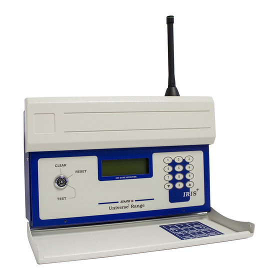
Introduction The Iris+ is a wireless personal attack system ideal for use in all types of nancial, industrial and commercial premises, where sta need the security of a personal attack alarm with total mobility. The use of the latest techniques in design with the extensive use of surface mount technology and microprocessors makes Iris+ a highly reliable, exible and user friendly system. -
Page 7: Accessing The Engineering Menus
Accessing the engineering menus To access the engineering menus, follow the steps listed below: Once powered and the Iris+ has completed system and System Clear con guration checks, the LCD screen will display: 08/05/18 13:26 Turn the front panel key to reset. The screen will change *** SYSTEM RESET *** to display: 13:26... -
Page 8: Checking Background Interference Levels
Checking background interference levels ‘Accessing the Access the Main Menu by following the operations listed under the previous engineering menus ’ section. The Iris+ should now be set up to Monitor Background Signals as their presence at a high level may e ect the performance of the system. -
Page 9: How To Reduce Interference
Using one or a combination of the above it should be possible to reduce the background carrier signal at the Iris+ receiver to an acceptable level. Should the above steps fail to suitably reduce interference, contact EMS Technical Support for more information. -
Page 10: Installation
Installation The Iris+ receiver consists of two sections, rstly the front casing which houses the receiver / processor PCB and secondly the rear casing which houses the external connection PCB. The installation of the Iris+ receiver requires the separation of the two sections and the xing of the rear back box section to the wall. - Page 11 7 Check rear tamper 8 Fix back box O er the back box to the wall. All four circled positions must Ensure that the rear tamper switch be used, to OUT- OUT+ TAMPER TAMPER operates. If necessary, remove the unit ensure a HARDWIRED INPUTS REMOTE...
- Page 12 PAGER RS485 BUSY RX TX RX TX RX VALID TX 3 WAY KEY 10 Re-attach front section 11 Replace wing nuts SWITCH COMMON POS 3 POS 2 USB-BOOT POS 1 NORMAL PORT RADIO RX BATTERY +3V3 Re-attach front Replace all four NORMAL Iris II END OF...
-
Page 13: Iris+ Back Box Connections Explained
The Pager 232 connector is a RS232 port which is used for (CTS, RX, 0V, DTR & TX) connection to an EMS text pager transmitter . The port is also used to receive information from EMS alarm control equipment and also pass this to the pager transmitter. - Page 14 Iris 12V OUT 12Vdc output which can be used if required, to trigger inputs 1-8. INPUT 8 Hardwired Input 8 programmable for N/O or N/C operation. 5-12Vdc applied or removed to trigger dependant on programming. INPUT 7 Hardwired Input 7 programmable for N/O or N/C operation. 5-12Vdc applied or removed to trigger dependant on programming.
-
Page 15: Post Installation Testing
Post installation testing Having installed the Iris+ receiver and transmitters, re-test all transmitters from their xed positions. With the Iris+ key turned to the test position, tested transmitter’s unique identities will displayed on the screen, along with their signal strength readings. A typical screen shot is shown below. -
Page 16: Operating Instructions
Operating instructions Keyswitch TEST position; all transmitters or hard wired inputs programmed to the system are able to be tested. A full alarm / local transmission or hard wired input activation will be acknowledged on the LCD screen and the buzzer will sound for approximately 1 second. With the unit set to the factory preset, whilst in this key position none of the relays should be observed to change state upon receipt of a valid transmission or hard wired input activation. -
Page 17: Adding A Transmitter
Adding a transmitter To add any additional transmitters, access the Main Menu by following the operations listed under the previous ‘Accessing the engineering menus ’ section. Now, follow the steps listed below: Press the button four times, the screen will now Time and Date display: >... -
Page 18: Naming A Transmitter
Naming a transmitter To change the name of any transmitters, access the Main Menu by following the operations listed under the previous ‘Accessing the engineering menus ’ section. Now, follow the steps listed below: Press the button four times. The screen will now Time and Date display: >... - Page 19 By using the button to move left or the button to move right, move to the letter or number required. Press button to select the character. Repeat until all letters have been selected. Once completed press the button to save the information.
-
Page 20: Deleting A Transmitter
Deleting a transmitter To delete a transmitter, access the Main Menu by following the operations listed under the ‘Accessing the engineering menus’ section. previous Now, follow the steps listed below: Press the button four times. The screen will now Time and Date display: >... -
Page 21: Add A New User
Add a new user To gain access to Iris+ a valid PIN number must be entered from the keypad. Each PIN programmed into the system will have a security level associated with it, this is know as the access level and will determine which features are available to the holder of a particular PIN. - Page 22 Press the button once and the screen will display: View Users > Change Pin < Add 6 Digit User 2=Help 13:55 Press the button once and the screen will display: | * Change PIN for ? * | > 00/ Engineer, 01 <...
-
Page 23: Transmitter Grouping
Transmitter grouping Each of the transmitters programmed into Iris can be allocated to a transmitter group. These groups can then be assigned to make one or more relays operate. This will allow a wide variety of options to be set up where designated transmitters will operate speci c relays. The Menu structure for the Grouping Task is shown below. - Page 24 Example transmitter grouping The following example shows how to assign an alarm transmission from handpush 001, to transmitter group 1 (Tgroup1). Follow the steps below: ‘Accessing the Access the Main Menu by following the operations listed under the previous engineering menus ’...
-
Page 25: Relay Output Con Guration
Relay output con guration Available events that can be used to make the Iris+ relay outputs operate are as follows: NOTHING No action to be taken GROUP: HUA ALARM* Raid alarm transmissions GROUP: HUA LOCAL* Raid local alert transmissions GROUP: DISPLAY* Events to be displayed, not logged GROUP:... - Page 26 The following example shows how to con gure Output 4 (Relay 3) to change state upon an alarm transmission. This example could be used to operate a Piezo Sounder. Follow the steps listed below: ‘Accessing the Access the Main Menu by following the operations listed under the previous engineering menus ’...
-
Page 27: Example Relay Wiring
Example relay wiring The example below shows the wiring of the Piezo Sounder into Relay 3, to match the previously Relay output con guration detailed section: Iris+ back box OUT- OUT+ TAMPER TAMPER HARDWIRED INPUTS REMOTE BUZZER HARDWIRED INPUTS Important note: This is an example only. -
Page 28: Helpful Hints
Receiver does Transmitter See appendix 1 for compatible respond to a transmitter compatible with system transmitters Receiver does Transmitter damaged Replace transmitter or return respond to a transmitter to EMS for repair Page 28 of 32... -
Page 29: Glossary
Glossary *Carrier received (precedes time on display) Aerial Tamper Aerial has been removed or tampered with Call In Fail Transmitter failed to call in three successive times (precedes Txer Details) Call In Fail Transmitter has failed to call in a rst or second time (log event only) RFI Detected after a period of 30 seconds (precedes time on display) 12Vdc PSU below 10.2Vdc, +/- 0.3Vdc threshold (precedes time on display) R.F.I... -
Page 30: Technical Speci Cations
Technical Speci cations Dimensions H 195mm x W 296mm x D 110mm Physical Weight 4 kg Environmental Temperature -10 to +55 degrees C Humidity Up to 75% non-condensing 458.5 to 458.8 MHz Operating frequency channel spacing 25khz (MPT 1329) -120 dBm for 12 dB sinad NBFM radio strength RF sensitivity indication dynamic range of 60 dB AFC capture and hold +/- 3 KHz... - Page 32 The information contained within this document is correct at time of publishing. EMS Ltd reserves the right to change any infomation regarding products as part of its continual development, enhancing new technology and reliability. The latest issue of this document can be found by visiting www.emsgroup.co.uk.
Need help?
Do you have a question about the iris+ and is the answer not in the manual?
Questions and answers