
Related Manuals for EMS FusionRLM


Summary of Contents for EMS FusionRLM
- Page 1 PROGRAMMING MANUAL ©2024 EMS Ltd. All rights reserved. Page 1 of 30 TSD062-99 (Issue 7) 10/09/2024 AJM...
-
Page 2: Table Of Contents
Audio Detect Batt Smooth Analogue Value 35 Mode Serial Data Radio Channels Channel Spacing Manual Channel Selection How to improve signal levels Analogue value table ©2024 EMS Ltd. All rights reserved. Page 2 of 30 TSD062-99 (Issue 7) 10/09/2024 AJM... -
Page 3: Introduction
All products should be kept in their packaging until they are due to be installed, to minimise the risk of damage. Retain all packaging until the installation activities have been completed. Should any product be found to be surplus to requirements, or require returning to EMS, the original packaging should be used. ©2024 EMS Ltd. All rights reserved. -
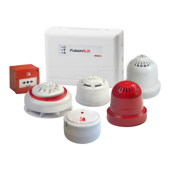
Page 4: Equipment Identification
Other wireless devices Wireless infrastructure Wireless input / Wireless door Fusion loop output unit control (WDC) module Wireless call point Wireless remote indicator module (RIM) ©2024 EMS Ltd. All rights reserved. Page 4 of 30 TSD062-99 (Issue 7) 10/09/2024 AJM... -
Page 5: Loop Module Overview
Exiting from a menu option is achieved automatically after 30 seconds or by pressing the ‘BACK’ button located on the loop module. ©2024 EMS Ltd. All rights reserved. Page 5 of 30 TSD062-99 (Issue 7) 10/09/2024 AJM... -
Page 6: Menu Structure
Batt Smooth † Analogue 35† Serial Data † Currently Used Scan Time Auto Select ‡ Manual Select ‡ First Channel Second Channel ©2024 EMS Ltd. All rights reserved. Page 6 of 30 TSD062-99 (Issue 7) 10/09/2024 AJM... -
Page 7: Loop Module Address
01010110 11110110 00101110 10011110 01100110 11010110 00001110 10101110 01011110 11100110 00110110 10001110 01101110 11011110 00010110 10110110 01001110 11101110 00111110 10010110 01110110 11001110 00011110 10111110 01111110 ©2024 EMS Ltd. All rights reserved. Page 7 of 30 TSD062-99 (Issue 7) 10/09/2024 AJM... -
Page 8: Loop Module Menu Options
Further device status information on the displayed device is available by pressing the rotary control . This allows the following menus to be viewed (see overleaf). ©2024 EMS Ltd. All rights reserved. Page 8 of 30 TSD062-99 (Issue 7) 10/09/2024 AJM... -
Page 9: Fault Status
The analogue values seen on the fire control panel for devices in this state are shown below: Analogue value Detector Manual call point Sounder Input / output device ©2024 EMS Ltd. All rights reserved. Page 9 of 30 TSD062-99 (Issue 7) 10/09/2024 AJM... - Page 10 The analogue values seen on the fire control panel for devices in this state are shown below: Analogue value Detector Manual call point Sounder Input / output device ©2024 EMS Ltd. All rights reserved. Page 10 of 30 TSD062-99 (Issue 7) 10/09/2024 AJM...
-
Page 11: Alarm Status
This menu shows information on the current alarm status of the device. The available alarm descriptions are described below: No Alarm Present – this indicates the device is currently not in an alarm or pre-alarm condition. ©2024 EMS Ltd. All rights reserved. Page 11 of 30 TSD062-99 (Issue 7) 10/09/2024 AJM... - Page 12 * The analogue value for the normal and closed input status is shown in relation to the devices signal strength. Therefore this can vary between 16, 14 or 13. ©2024 EMS Ltd. All rights reserved. Page 12 of 30 TSD062-99 (Issue 7) 10/09/2024 AJM...
-
Page 13: Battery Level
Pack 2 Missing – this indicates a battery from pack 2 is missing. The battery must be inserted on the device for continued reliable operation. This is represented by displaying an ‘X’ symbol. ©2024 EMS Ltd. All rights reserved. Page 13 of 30... -
Page 14: Signal Level
A level from 0 - 45dB is shown to indicate the levels. A table with additional signal level details is shown at the end of this section. ©2024 EMS Ltd. All rights reserved. Page 14 of 30... - Page 15 123 seconds. The loop module to device information is automatically updated every 6 hours or if a manual update is requested. The minimum recommend level is 20dB on each channel. ©2024 EMS Ltd. All rights reserved. Page 15 of 30 TSD062-99 (Issue 7) 10/09/2024 AJM...
-
Page 16: Manual Update
Ident This menu shows the device’s unique 5 digit identification number. Software version This menu shows the device’s current software version. ©2024 EMS Ltd. All rights reserved. Page 16 of 30 TSD062-99 (Issue 7) 10/09/2024 AJM... -
Page 17: Device Address
‘ON’ and ‘OFF’ . It is also possible to select individual output devices and send commands to turn the unit’s relay outputs ‘ON’ and ‘OFF’ . Note: If the unit is a dual output device, both outputs will operate. ©2024 EMS Ltd. All rights reserved. Page 17 of 30... - Page 18 Press the rotary control to confirm the device address. The screen will Detector Added display: Press the ‘BACK’ button, to return to the front display: DEV06 AL00 FT00 ©2024 EMS Ltd. All rights reserved. Page 18 of 30 TSD062-99 (Issue 7) 10/09/2024 AJM...
- Page 19 ‘BACK’ button to return to the previous display. If the device ident displayed is correct, turn the rotary control until the IDENT: 23456 screen displays: Continued overleaf. ©2024 EMS Ltd. All rights reserved. Page 19 of 30 TSD062-99 (Issue 7) 10/09/2024 AJM...
- Page 20 Press the rotary control to confirm the device address. The screen will 01 Added Sounder display: Press the ‘BACK’ button, to return to the front display: DEV07 AL00 FT00 ©2024 EMS Ltd. All rights reserved. Page 20 of 30 TSD062-99 (Issue 7) 10/09/2024 AJM...
-
Page 21: Equipment Familiarisation
Ident number PRESS HERE TO LOG ON www.emsgroup.co.uk Combined Sounder and Detector Base 1d872 Status LED RevX DD/MM/YY Note; as viewed at 180 degree device rotation. ©2024 EMS Ltd. All rights reserved. Page 21 of 30 TSD062-99 (Issue 7) 10/09/2024 AJM... - Page 22 OUTPUT 1 OUTPUT 2 EXPAN1 Device IP- IP+I P- IP+ 3VDC SET RST 3VDC SET RST N/OC OM N/C N/OC OM N/C powered (both pins linked) ©2024 EMS Ltd. All rights reserved. Page 22 of 30 TSD062-99 (Issue 7) 10/09/2024 AJM...
-
Page 23: Remove Device
This menu when entered shows detailed information on the fault status of the loop module. If multiple faults are outstanding for the interface then by turning the rotary control they can be individually viewed. The available fault descriptions are described overleaf: ©2024 EMS Ltd. All rights reserved. Page 23 of 30 TSD062-99 (Issue 7) 10/09/2024 AJM... -
Page 24: Background Level
The analogue value seen on the fire control panel for when both channel 1 and channel 2 are in this state, is shown below: Indicates HIGH background level Indicates CAUTION background level Indicates MEDIUM background level Indicates GOOD background level ©2024 EMS Ltd. All rights reserved. Page 24 of 30 TSD062-99 (Issue 7) 10/09/2024 AJM... -
Page 25: Fast Test
Fast Test 00:59 required and press the rotary control. The display will show: Press the ‘BACK’ button, to return to the front display: DEV06 AL00 FT00 ©2024 EMS Ltd. All rights reserved. Page 25 of 30 TSD062-99 (Issue 7) 10/09/2024 AJM... -
Page 26: Ident
When using multiple loop modules, the radio channels should be checked to ensure the same channels are not used on loop modules that are in range of each other. For further assistance, follow the channel spacing guidance overleaf, or contact EMS technical support. -
Page 27: Channel Spacing
Ch20: 868.824 MHz Loop module 2 Ch8: 868.223 MHz Ch24: 868.924 MHz Ch12: 868.323 MHz Ch28: 869.024 MHz Ch16: 868.423 MHz Ch32: 869.125 MHz Loop module 1 ©2024 EMS Ltd. All rights reserved. Page 27 of 30 TSD062-99 (Issue 7) 10/09/2024 AJM... -
Page 28: Manual Channel Selection
Signal levels successfully Carry out a survey to re-check signal improved. levels. Contact technical support department for further advice. ©2024 EMS Ltd. All rights reserved. Page 28 of 30 TSD062-99 (Issue 7) 10/09/2024 AJM... -
Page 29: Analogue Value Table
Background level good Detector Radio signal strength medium Detector Radio signal strength good Detector Detector head dirty Detector Pre-alarm Call point Alarm condition Detector Alarm condition ©2024 EMS Ltd. All rights reserved. Page 29 of 30 TSD062-99 (Issue 7) 10/09/2024 AJM... - Page 30 The information contained within this literature is correct at time of publishing. EMS reserves the right to change any information regarding products as part of its continual development enhancing new technology and reliability. EMS advises that any product literature issue numbers are checked with its head office prior to any formal specification being written.
Need help?
Do you have a question about the FusionRLM and is the answer not in the manual?
Questions and answers