Table of Contents
Advertisement
Advertisement
Table of Contents

Subscribe to Our Youtube Channel
Related Manuals for Arjohuntleigh Maxi 500


Summary of Contents for Arjohuntleigh Maxi 500
- Page 1 Maxi 500 Maintenance and Repair Manual 5001-00553-EN rev 5 • 1/2018...
- Page 2 © ArjoHuntleigh 2014. As our policy is one of continuous improvement, we reserve the right to modify designs without prior notice. The content of this publication may not be copied either whole or in part without the consent of ArjoHuntleigh.
-
Page 3: Table Of Contents
Table of Contents Safety Instructions ........................4 General Information..........................4 Product and Technical Description ..................5 Introduction............................... 5 Features ..............................5 Risk Assessment Checklist for Service Technician.................. 6 Suggested Tools ............................7 Recommended Spares..........................7 Threadlocker Application.......................... 8 Torque, Lubrication and Threadlocker Data..................... 9 Preventive Maintenance Schedule.................. -
Page 4: Safety Instructions
B. Unauthorized modifications on any ArjoHuntleigh equipment may affect its safety and are in breach of any warranty on it. ArjoHuntleigh will not be held responsible for any accidents, incidents or lack of performance that occur as a result of unauthorized modifications to its products. -
Page 5: Product And Technical Description
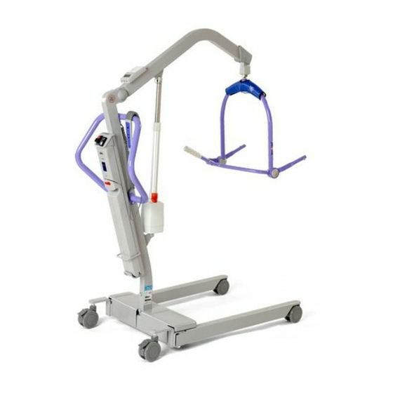
Product and Technical Description Introduction The Maxi 500 is a mobile patient lifter and is used for transferring patients from the bed, chair or the toilet. The floor lift has a maximum safe working load (SWL) of 227kg (500lb). NOTE: The SWL will depend on the lift’s configuration and attachments. Always refer to the maximum SWL of the lowest rated attachment. -
Page 6: Risk Assessment Checklist For Service Technician
Failure to meet these requirements could result in personal injuries and/or unsafe equipment. Risk Assessment Checklist for Service Technician WARNING: IF IN DOUBT, CONTACT YOUR LOCAL ArjoHuntleigh REPRESENTATIVE. DO NOT TAKE UNNECESSARY RISKS. The following assessment MUST be made before carrying out servicing, repair work or installations: •... -
Page 7: Suggested Tools
Suggested Tools • Standard tool kit. • Socket Allen key: (4 mm ST82) (5 mm ST274) (6 mm ST55) (8 mm ST87). • Sling clip gauge ST331. • Load test equipment Recommended Spares • Casters • Fuse • Hand Control LEFT RIGHT Fig. -
Page 8: Threadlocker Application
Threadlocker Application Refer to the manufacturer’s instructions found on the container before use, in addition to the following information: The procedure for correctly applying Loctite 242 and Loctite 243 (Blue color) threadlocking is as follows: • Clean both of the joint faces with Loctite 7063 cleaner or a lint-free cloth moistened with acetone or another suitable solvent. -
Page 9: Torque, Lubrication And Threadlocker Data
Torque, Lubrication and Threadlocker Data Thread retaining: Apply Loctite 243 when no threadlocking patch has been pre-applied. When replacing a part with pre-applied threadlocking, the part should be replaced by a new part using pre-applied threadlocking. Loctite 243 Loctite 243 Loctite 243 Loctite 243 Loctite 243... - Page 10 Loctite 243 40 N•m (29.5 lbf•ft) (2) Loctite 243 Loctite 243 50 N•m (37 lbf•ft) (2) 40 N•m (29.5 lbf•ft) (2) Loctite 243 40 N•m (29.5 lbf•ft) (2) Loctite 243 Loctite 243 22 N•m 16 N•m (12 lbf•ft) (2) (16 lbf•ft) Loctite 243 35 N•m (26 lbf•ft) (2) Food grade...
-
Page 11: Preventive Maintenance Schedule
Preventive Maintenance Schedule WARNING: Service must be carried out by qualified personnel, using correct tools and with a knowledge of procedures. Failure to meet these requirements could result in personal injuries and/ or unsafe equipment. Call out TO BE INSPECTED ANNUALLY BY A QUALIFIED TECHNICIAN reference (page 12-13) •... -
Page 12: Technician Inspections
Technician Inspections Fig. 4... - Page 13 Fig. 5...
-
Page 14: Troubleshooting
• Call for service (charger may be faulty). seated but no lights are visible. Yellow indicator light does • Internal batteries need replacing. Call ArjoHuntleigh for not go off after several hours replacement. of charging time. Battery pack indicates it is •... -
Page 15: Service Procedures
Service Procedures SP1 - Checking for Updates SP2 - Checking the Battery and Charger SP3 - Checking for Corrosion and Damage SP4 - Full Feature Test SP5 - Checking the Anti-Crush System Replacing Boom - SP17 Replacing Scale Calibration - SP19 DPS/Spreader Replacing Scale - SP18 Bar from a Load... -
Page 16: Service Procedure 1 - Check For Updates
Service Procedure 2 - Checking the Battery and Charger Checking the Battery ArjoHuntleigh has added a fuse in battery NDA0100-20. There is no noticible difference between the former and the new battery version other than the labeling (see following pictures for more details on the former battery labeling and the new battery labeling). -
Page 17: Battery Test
condition on a meter. Battery Test Battery without fuse - former labeling With former battery tester. The battery to be tested must be charged for at least 12 hours before the test. Connect the tester to the battery. When the tester is fully connected, turn the test switch right or left for 1-2 seconds and take a quick reading on the meter. -
Page 18: Check The Battery Charger (Nda8200)
Check the battery charger (NDA8200) Inspect charger and cable for damage. Battery charger Test charger for operational condition as follows: • Measure charger output voltage (directly on output socket prongs). Charger status indicator LED should be GREEN. Voltage reading should be between 27.04V and 28.16V. •... -
Page 19: Service Procedure 3 - Checking For Corrosion And Damage
Service Procedure 3 - Checking for Corrosion and Damage This verification will help preserve the safety and performance of the product. To Verify: 1) Front caster 2) Legs 3) Braked caster 4) Base 5) Mast 6) Battery 7) Control box 8) Handle 9) Hand Control 10) Boom... -
Page 20: Service Procedure 4 - Full Feature Test
Service Procedure 5 - Verifying the Anti-Crush System Place an object beneath the boom (e.g. place Maxi 500 boom over a table). Press the “down” button on the unit’s control panel. The actuator should stop operating and the downward motion should cease immediately when the boom makes contact with an object. -
Page 21: Service Procedure 6 - Replacing The Front Wheel
Service Procedure 6 - Replacing the Front Wheel OLDER STYLE CASTER Position the Maxi 500 base in order to get easy access to the front wheels. Remove leg cover. Using a rubber mallet, unclip the caster by hammering on top of it. -
Page 22: Service Procedure 8 - Replacing The Leg Actuator
Service Procedure 7 - Replacing the Back Wheels Position the Maxi 500 base in order to get access to the back wheels. Flat Head Remove the caster by unscrewing the flat head socket Socket Screw screw, securing the wheel by the hexagonal section (see Fig. - Page 23 Remove cotter pins from pivots at both ends of leg actuator, and dispose of them. Unscrew the left tie rod end kit from the left leg and remove from bracket. Unscrew the shoulder bolt that holds the shifter plate in place and pull it away from the base. You will need enough clearance to allow removal of the actuator (see Fig.
-
Page 24: Service Procedure 9 - Replacing The Legs
Service Procedure 9 - Replacing the Legs Lock the rear casters to make sure the lift stays stable during maintenance. Remove the base cover and unscrew the tie rod end from the leg to be replaced and remove from bracket (see Fig. 16). Dispose of the nylon nut. Unscrew the leg pivot bolt that holds the leg to the base assembly and remove leg (see Fig. -
Page 25: Service Procedure 10 - Adjusting The Legs
Service Procedure 10 - Adjusting the Legs Check if the legs are square with the base. If not, perform the following procedure: Using a heat gun, heat the area between the tie rods and the nuts so as to liquefy any loctite that had been applied there previously. -
Page 26: Service Procedure 11 - Replacing The Base Assembly
Service Procedure 11 - Replacing the Base Assembly Lock the rear casters to make sure the lift stays stable during maintenance. Dismantle the mast assembly (see “Service Procedure 12 - Replacing the Mast”). (Note: Leave the actuator attached to mast). Lock the casters on the new base assembly to make sure the lift stays stable. -
Page 27: Service Procedure 12 - Replacing The Mast
Service Procedure 12 - Replacing the Mast Lock the rear casters to make sure the lift stays stable during maintenance. Remove the battery pack. Dismantle the boom and DPS/spreader bar assembly (see “Service Procedure 17 - Replacing the Boom”). Dismantle the actuator from the mast (see “Service Procedure 16 - Replacing the Boom Actuator”). -
Page 28: Service Procedure 13 - Replacing The Handle
Service Procedure 13 - Replacing the Handle Lock the rear casters to make sure the lift stays stable during maintenance. Unscrew the two screws at the lower end of the handle on each side of the mast and the one at the top (see Fig. -
Page 29: How To Close The Control Box
How to Close the Control Box Insert the top end of the cover under the switch panel (see Fig. 24). Carefully position the wires. Be sure not to pinch a wire behind a screw or the edge of the control box. Fasten both screws (Phillips #2) near the bottom end (see Fig. - Page 30 NEW STYLE BOARDS Remove control box cover (see service procedure 14). Unplug J1 and J2 connectors (see Fig. 27). connector Using long nose pliers, remove the cirucit board from the plastic standoffs holding it in place. Replace the new main PCB circuit in place as shown on Fig.
- Page 31 NEW STYLE BOARDS a) Safe working load: By actuating the handset, make sure that the lift raises the safe working load on its entire stroke (227-238 kg [500-525 lb]). If not, adjust the current limiter with the potentiometer RV1 (see Fig. 29). Keep the safe working load raised for the next step.
-
Page 32: Service Procedure 15 - Replacing The Battery Discharge Indicator Pcb
Service Procedure 15 - Replacing the Battery Discharge Indicator PCB Remove control box cover. Unplug J5 and J7 connectors as shown on electric diagram from battery discharge indicator PCB. Unscrew both nuts holding the battery discharge indicator PCB using a 5mm socket, and remove device. -
Page 33: Service Procedure 16 - Replacing The Boom Actuator
Service Procedure 16 - Replacing the Boom Actuator Lock the rear casters to make sure the lift stays stable during maintenance. Top of actuator Disconnect the actuator from the power supply. The connector is located under the base cover, together with the connector for the leg actuator, on the left side of the lift (see Fig. - Page 34 Fig. 32 Install the DPS or spreader bar (see “Service Procedure 20 - Replacing the DPS/Spreader Bar from a Load Cell”) and slide the boom end cap in place over the fasteners. Install the scale on the boom. Assemble the actuator to the boom. NOTE: If the boom is reassembled using an attachement with a shoulder bolt, make sure to secure the shoulder bolt with Loctite 243 and the stover locknut.
-
Page 35: Service Procedure 18 - Replacing The Scale
Service Procedure 18 - Replacing the Scale NOTE: From SN300155061, the scale is sold with the accessory and cannot be separated. Removing the scale Lock the rear casters to make sure the lift stays stable during maintenance. Remove the battery pack. Dismantle the scale display cover by removing the four screws behind the box (see Fig. -
Page 36: Installing The Scale
Remove the load cell from the boom. Slide back the boom end cap. If necessary, use soap and water to ease displacement. Warning: Remove the cotter pin from the clevis pin, Make sure slide it out and dispose of it (see Fig. 32). that the inclined Pull out load cell wire from boom. - Page 37 Process #1 Adjust switch SW4 to the CAL position (DOWN) (see Process #2). With zero weight applied to the system (including sling), press SW1 (weight button) to adjust R3 (offset potentiometer) so that the display reads a +30 pound offset. Note: Display will periodically flash CAL to let you know you are in CAL mode.
- Page 38 “zero” No calibrated weight applied. “2 pt” Two- point calibration curve, zero and full scale. “3 pt” Three-point calibration curve; zero, half and full scale. “save” Saves the calibration data. “quit” Quits without saving the calibration data To enter the CAL mode, access the calibration button by removing the four (4) screws from the back of the display assembly.
- Page 39 d) Press the left button to save or right button to toggle to "quit". Select "quit" by pressing the left button to quit without saving changes. e) Press the left button again to save and the display will show “SAV’d”. Calibrate the scale with Three-point calibration curve;...
-
Page 40: Error Messages
Error Messages RUN MODE Battery will display for Approximately 10 sec Battery resource is low after start-up Battery without display Battery resource is critically low Over-range display Excessive load on scale Low data input to Excessive load on scale electronics CALIBRATION MODE Calibration slope is lower than expected ERROR CAL TO LOW... -
Page 41: Service Procedure 20 - Replacing The Dps/Spreader Bar From A Load Cell
Service Procedure 20 - Replacing the DPS/Spreader Bar from a Load Cell NOTE: From SN300155061, the scale is sold with the accessory and cannot be separated. Lock the rear casters to make sure the lift stays stable during maintenance. Extract the spring pin from the pivot bolt and the load cell extension block. Unscrew the pivot bolt from the load cell extension block. -
Page 42: Service Procedure 21 - Replacing The Hand Control
Service Procedure 21 - Unplug the hand control from the socket located on the left side of the Replacing the Hand Control control box. Remove the battery pack. Hand Control socket Fig. 37 Remove the top screw of the handle with a 4mm Allen key and slide out the wire from the bracket (see Fig. -
Page 43: Service Procedure 22 - Safe Working Load Test (Local Requirement)
Two-point spreader bar (with or without DPS (with or without scale) scale) • Set up the ArjoHuntleigh Load Test • Set up the ArjoHuntleigh Load Test Kit as shown and test to safe working Kit as shown and test to the safe load (SWL). -
Page 44: Service Procedure 23 - Verifying The Slings
• Refer to the above illustration and insert approved method of checking machined diameter of ST331 Sling Clip serviceability of the ArjoHuntleigh plastic Gauge into the large diameter the keyhole sling clip and other method should slot in the plastic clip. -
Page 45: Service Procedure 24 - Replacing The Dps Or Spreader Bar
Service Procedure 24 - Replacing the DPS or spreader bar 1. Lower the boom and lock the castors to make sure the lift stays stable during maintenance. 2. Slide up the boom end cap to access the DPS or spreader bar fastenings. With a damp cloth, lubricate the boom tubing to facilitate the cap movement. -
Page 46: Service Procedure 25 - Anti-Sway Adjustment
Service Procedure 25 - Anti- sway adjustment 1. Lower the boom and lock the castors to make sure the lift remains stable during maintenance. 2. Slide up the boom end cap to access the DPS or spreader bar fastenings. With a damp cloth, lubricate the boom tubing to facilitate the cap movement. 3. -
Page 47: Technical Specifications
WARNING: Radio transmitting devices such as mobile telephones, two-way radios, etc., should never be used near the MAXI 500, since they can interfere with the function of the lift. Cables from potentially strong sources of electromagnetic fields should not be placed near the unit. - Page 48 60 cm 12 cm 2.5 cm 56 cm 114 cm CSP stands for Central Suspension Point: a reference point on the lift for measurements. On the Maxi 500 the CSP is the Accessory attachment point located at the boom end.
-
Page 49: Electromagnetic Compatibility
Electromagnetic Compatibility Electromagnetic Compliance The Maxi 500 has been tested for compliance with current regulatory standards regarding its capacity to block EMI (electromagnetic interference) from external sources. Nonetheless, some procedures can help reduce electromagnetic interferences: • Use only ArjoHuntleigh cables and spare parts to avoid increased emissions or decreased immunity which can compromise the correct functioning of the equipment. -
Page 50: Electromagnetic Immunity
Guidance and Manufacturer’s Declaration - Electromagnetic Immunity - For all Equipment and Systems The Maxi 500 is intended for use in electromagnetic environment specified below. The customer or the user of the Maxi 500 should assure that it is used in such an environment. - Page 51 Recommended separation distances between portable and mobile RF communications equipment and the Maxi 500. The Maxi 500 is intended for use in electromagnetic environment in which radiated RF disturbances are controlled. The customer or the user of the Maxi 500 can help prevent electromagnetic interference by...
- Page 52 AUSTRALIA FRANCE POLSKA ArjoHuntleigh Pty Ltd ArjoHuntleigh SAS ArjoHuntleigh Polska Sp. z o.o. 78, Forsyth Street 2 Avenue Alcide de Gasperi ul. Ks Piotra Wawrzyniaka 2 O’Connor CS 70133 PL-62-052 KOMORNIKI (Pozna ) AU-6163 Western Australia FR-59436 RONCQ CEDEX Tel: +48 61 662 15 50 Tel: +61 89337 4111 Tél: +33 (0) 3 20 28 13 13...
- Page 53 Hans Michelsensgatan 10 211 20 Malmö, Sweden www.arjohuntleigh.com ArjoHuntleigh is a world-leading provider of integrated products and solutions that improve the lives of patients and residents with reduced mobility. We help healthcare facilities deliver wellness and effective everyday care, early mobilisation, safe patient handling, venous thromboembolism prevention, pressure injury prevention, hygiene routines, bariatric care and diagnostics.
Need help?
Do you have a question about the Maxi 500 and is the answer not in the manual?
Questions and answers