Table of Contents
Advertisement
Quick Links
Advertisement
Table of Contents

Related Manuals for Arjohuntleigh Maxi Sky 600


Summary of Contents for Arjohuntleigh Maxi Sky 600
- Page 1 Maxi Sky 600 Technical Manual 001.14155.33 rev. 8 • December 2017...
- Page 2 Design Policy and Copyright ® and ™ are trademarks belonging to the ArjoHuntleigh group of companies. © ArjoHuntleigh 2017. As our policy is one of continuous improvement, we reserve the right to modify designs without prior notice. The content of this publication may not be copied either whole or in part without the consent of...
-
Page 3: Table Of Contents
Table of Contents General Information ............4 Care and Maintenance............27 Preventive Maintenance Schedule........27 Introduction ................4 How to use this Manual ............4 User Inspections ..............27 Equipment Identification ............4 Inspections by an Authorized Service Technician ....28 Safety Instructions .............. -
Page 4: General Information
WARNING: Do not attempt to use this equipment Please take the time to read the entire without understanding this manual. manual, including the section on “Safety Instructions and Warnings”. To ensure a safe operation of the Maxi Sky 600, read the Your manual contains important entire manual carefully, especially the section on “Safety... -
Page 5: Safety Instructions
Safe Working Load kg (750 lb). • ArjoHuntleigh ceiling lifts are specifically designed for The Maxi Sky 600 has been designed with a lifting use with KWIKtrak ceiling rail systems, and capacity of 272 kg (600 lb). ArjoHuntleigh slings and accessories. -
Page 6: Part Designation
Part Designation Lift Cassette and Charger Station Legend 1) Maxi Sky 600 lift 10) Safety latch 2) Emergency lowering mechanism button 3) Allen key button DOWN 4) Track 13) Green power light* 5) Charging station 14) Emergency switch plastic insert... -
Page 7: Led Behavior
Hand Control The Maxi Sky 600 hand control can be infrared or wired. Universal Charger The Maxi Sky 600 comes equipped with a universal charging system that can be customized to fit the AC voltage outlets wherever they are sold. -
Page 8: Service Procedures
Remove the spreader bar. Place the Maxi Sky 600 on a solid table with the trolley facing downwards. Use pieces of wood under each side of the trolley to stabilize it and prevent it from moving. Make sure not to damage the contact blades. -
Page 9: Service Procedure #2- Replacing The Handset
#9 from step 9. Fig. 9 DO NOT ATTEMPT TO USE A BATTERY NOT AUTHORIZED BY ArjoHuntleigh. ArjoHuntleigh batteries are specially designed for ArjoHuntleigh charging systems. Attempting to use an unauthorized battery may seriously damage the lift and/or the charger. -
Page 10: Service Procedure #4 - Main Circuit Board Replacement
Service Procedures Service Procedure #4 - Main Circuit Board Replacement Remove the plastic shell from the chassis by performing service procedure #1, steps 1 to 9. Disconnect the main connector (see Fig. 10). Unscrew the 3 hexagonal screws using of an 8 mm socket (5/16) (see Fig. - Page 11 Service Procedures b. Unwind the strap completely. Fig. 11 Fig. 12 Rotate the drum to align the strap bolt with the large hole on the frame (see Fig. 13). Completely unscrew the strap bolt with a 6 mm Allen Large key and remove the old strap.
- Page 12 Service Procedures 11) Engage the transmission by turning the main shaft clockwise with the 8 mm Allen key (see Fig. 17). 12) Reassemble the lift by performing service procedure FOR LIFTS EQUIPPED WITH THE HIGH LIMIT SWITCH KIT (700-14075) Unscrew the high limit switch kit assembly’s 2 socket head cap screws with a 4 mm Allen key.
-
Page 13: Service Procedure #6 - Replacing The Trolley
Service Procedures Service Procedure #6 - Replacing the Trolley Remove the plastic shell from the chassis by performing service procedure #1, steps 1 to 9. Locking Locking Device Unfold the locking tab which is used to secure the trolley. Remove the trolley locking device with an 8 mm socket (see Fig. - Page 14 Service Procedures FOR LIFTS EQUIPPED WITH LIMIT PLATE (200.14070) Unscrew the two locknuts holding the limit switch plate (A) using an 8 mm socket tool and an 8 mm (5/16) wrench (see Fig. 25). Unscrew the two nuts of the limit switch (B) using a 3/16 in or 5-mm socket (see Fig.
-
Page 15: Service Procedure #8 - Replacing The Transmission
Service Procedures Service Procedure #8 - Replacing the Transmission Remove the plastic shell from the chassis by performing service procedure #1, steps 1 to 9. Remove the circuit board (refer to service procedure #4 steps 2 to 3). Remove the high limit switch (refer to service procedure #7 step 3 to 5). Remove the trolley (refer to service procedure #6 steps 2 to 4). - Page 16 Service Procedures Replace the 8 screws to fix the shell in place, use the long screws for plastic (a) and the shorter ones for metal (b) (see Fig. 33). Connect the hand control to the main circuit board making sure that the ferrite is not interfering inside the battery cavity and that the cable is secured passing through the cord grip built inside the main shell (see Fig.
- Page 17 Service Procedures For units equipped with a Brake Board circuit: Connect the hand control to the main circuit board and insert the ferrite over the brake circuit board (see Fig 34_a). Route the hand control cable as shown in Fig 35_a. Figure 35_a Figure 34_a Reinstall the batteries.
-
Page 18: Service Procedure #10 - Replacement Of Vertical Motor
Service Procedures Service Procedure #10 - Replacement of Vertical Motor Remove the plastic shell from the chassis by performing service procedure #1, steps 1 to 9. Disconnect the main connector from the circuit board. With an extracting tool (#005.00374), remove the two vertical motor wires from the main connector, position numbers 11 and 12 (see Fig. -
Page 19: Service Procedure #11 - Replacement Of Horizontal Motor
Service Procedures Service Procedure #11 - Replacement of Horizontal Motor Remove the plastic shell from the chassis by performing service procedure #1, steps 1 to 9. Disconnect the main connector from the circuit board. With an extractor tool (#005.00374), remove the two wires of the horizontal motor from the main connector (position numbers 3 and 6). -
Page 20: Connection Diagram, Main Connector
Service Procedures #13a - 13e for ECS Track System The Maxi Sky 600 is now available for use with the Kwiktrak Enhanced Charging System. This track system allows the cassette to benefit from automated charging wherever it is on the track. It eliminates the need to send the unit back to a charge station after the patient transfer. - Page 21 Service Procedure 13a: Emergency Stop/Plastic Insert Switch The Maxi Sky 600 is now equipped with a different main circuit board, which functions with a new power switch. Previous models were both turned on and off by pulling the red emergency cord. The current model is still turned off by pulling on the red cord.
- Page 22 Service Procedures Service Procedure 13c: Replacing the ECS Wire Harness After removing the cassette’s plastic bottom panel and its main housing (as per the technical manual): Remove the contact box (see Fig. 49), and remove the clear plastic cable guard from the cassette’s trolley using an 8 mm (5/16”) socket.
- Page 23 Service Procedures Service Procedure 13d: Replacing the ECS Circuit Board CAUTION: Before performing this procedure, make sure that ESD (Electro-Static Discharge) protection is being employed to avoid damaging the electronic components Remove using an 8 mm socket spacer CAUTION: When reinserting the ECS circuit board, be careful to align the connector pins perfectly to their socket...
- Page 24 Service Procedures Service Procedure 13e: Replacing the Plastic Insert for the On/off Switch After getting access to the cassette’s frame and after removing the ECS circuit board (see Fig. 51): Unplug the hand set wire from the circuit board. Unplug main circuit board connector and the wires to the on/odd switch. Unscrew the bolts that secure the main circuit board to the frame using an 8 mm (5/16”) socket.
-
Page 25: Connection Diagram
Service Procedures Connection Diagram Main Connector Main Circuit Connector Wiring Positions 1) Red/white - From switch 2) Not used 3) Red - Lateral motor 4) Blue - High limit switch 5) Not used 6) Blue - Lateral motor 7) Not used 8) Blue - High limit switch 9) Black/white - Battery 10) Orange - From switch... -
Page 27: Care And Maintenance
WARNING: Safety related maintenance and authorized service must be carried out by qualified personnel, fully trained in servicing procedures by ArjoHuntleigh and equipped with proper tools. Failure to meet these requirements could result in personal injuries and/or unsafe equipment. -
Page 28: Inspections By An Authorized Service Technician
Care and Maintenance FREQUENCY Before Every two Every four Every year Every two Inspections for spreader Initially every months or months or years or bar and slings 500 cycles 1000 cycles 2500 cycles 5000 cycles Inspect all sling parts (attachments, fabric, stitch areas and strap) for signs of wear, discoloration, deterioration or loose... -
Page 29: Cleaning
WARNING: Always reinstall the rail end stoppers (if removed) after servicing. Cleaning To clean the Maxi Sky 600, wipe it down with a damp cloth using warm water and a disinfectant cleaner. Disinfectant wipes, supplied already impregnated with a 70% v/v solution of isopropyl alcohol, can also be used. -
Page 30: Strap Inspection
Loose threads in stitched areas danger for the resident or caregiver. ArjoHuntleigh recommends a thorough inspection of the straps every 2 months as follows: Noticeable... -
Page 31: Handling And Storage
Replace the battery when there is a noticeable reduction in the number of transfers that can be performed between charges. If you hear the Maxi Sky 600 lift beeping and notice a red light flashing, see the instructions in the “Troubleshooting” section of this manual to determine if it is a problem with the battery. -
Page 32: Annual Inspection
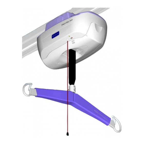
Weight Load Test As stated in the Maxi Sky 600 Instructions for Use, it is recommended that a load test on the ceiling lift at its save working load (SWL) be performed. This annual verification should the verify the following aspects: •... - Page 33 Care and Maintenance Using a measuring tape, measure between the track and the laser line at every track bracket, always taking the same reference point—either the top or the bottom of the track (see Fig. 61). NOTE: Be sure to use the same measuring tape throughout, as different measuring tapes may have varying looseness in their tape end hooks.
- Page 34 Care and Maintenance 12) Take measurements of the height of the track verses the laser line as you pass under each bracket (see Fig. 65 and Fig. 66). Fig. 65 Fig. 66 13) With the measurements mentioned above, fill the corresponding column (height loaded) in the weight load test form. Compare the measurements of the track height when loaded and unloaded.
-
Page 35: Testing The Ceiling Lift
Care and Maintenance Testing the Ceiling Lift Verifying the Soft Start and Soft Stop Features Without Load Press the button on the hand control. Observe as the vertical motor unravels the strap. The motor DOWN should not reach its top speed instantly. Top speed should be achieved only after approximately 1 second of time has elapsed. -
Page 36: Troubleshooting
Troubleshooting WARNING: Only a qualified technician is authorized to open the Maxi Sky 600 ceiling lift cassette. Alterations made to the Maxi Sky 600 ceiling lift cassette by someone other than a certified technician may cause serious injury. PROBLEM TO CHECK •... - Page 37 Clip it to the rail and charge the unit for 3 hours. If the yellow light is still The charging light on the ceiling lift cassette flashing, contact your local ArjoHuntleigh representative. continues flashing yellow and the light does •...
-
Page 38: Labels On The Lift
Labels on the Lift Maximum capacity/Service telephone number Date of manufacture, serial number, product code Product name ArjoHuntleigh Logo Emergency lowering system access identification Emergency stop identification Travel direction indicators Charger information Fig. 70... -
Page 39: Technical Specification
Maxi Sky 600 and should be kept at least 2.3 m away from it. Cables from potentially strong sources of electromagnetic fields should not be placed near the unit. - Page 40 Package Cardboard recyclable The lift Separated and recycled, according to the European Directive 2002/96/EG (WEEE). ArjoHuntleigh resident Handling products meet the requirements of Electromagnetic Compatibility (EMC) as stated in clause 12.5 of Annex 1 of the Medical Devices Directive 93/42/EEC.
- Page 41 Lift Dimensions Fig. 71...
-
Page 42: Electromagnetic Compatibility
Electromagnetic Emissions - For all Equipment and Systems The Maxi Sky 600 is intended for use in the electromagnetic environment indicated below. The customer or the user of the Maxi Sky 600 should assure that it is used in such an environment. -
Page 43: Electromagnetic Immunity
Electromagnetic Immunity - For all Equipment and Systems The Maxi Sky 600 is intended for use in electromagnetic environment specified below. The customer or the user of the Maxi Sky 600 should assure that it is used in such an environment. - Page 44 RF transmitters, an electromagnetic site survey should be considered. If the measured field strength in the location in which the Maxi Sky 600 is used exceeds the applicable RF compliance level above, the Maxi Sky 600 should be observed to verify normal operation. If abnormal performance is observed, additional measures may be necessary, such as reorienting or relocating the Maxi Sky 600.
- Page 45 Recommended separation distances between portable and mobile RF communications equipment and the Maxi Sky 600. The Maxi Sky 600 is intended for use in electromagnetic environment in which radiated RF disturbances are controlled. The customer or the user of the Maxi Sky 600 can help prevent electromagnetic interference by maintaining a minimum distance between portable and mobile RF communication equipment (transmitters) and the Maxi Sky 600 as recommended below, according to the maximum output power of the communications equipment.
- Page 47 POLSKA AUSTRALIA FRANCE ArjoHuntleigh Pty Ltd ArjoHuntleigh SAS ArjoHuntleigh Polska Sp. z o.o. 78, Forsyth Street 2 Avenue Alcide de Gasperi ul. Ks Piotra Wawrzyniaka 2 O’Connor CS 70133 PL-62-052 KOMORNIKI (Pozna ) AU-6163 Western Australia FR-59436 RONCQ CEDEX Tel: +48 61 662 15 50 Tel: +61 89337 4111 Tél: +33 (0) 3 20 28 13 13...
- Page 48 Hans Michelsensgatan 10 211 20 Malmö, Sweden www.arjohuntleigh.com ArjoHuntleigh is a world-leading provider of integrated products and solutions that improve the lives of patients and residents with reduced mobility. We help healthcare facilities deliver wellness and effective everyday care, early mobilisation, safe patient handling, venous thromboembolism prevention, pressure injury prevention, hygiene routines, bariatric care and diagnostics.
Need help?
Do you have a question about the Maxi Sky 600 and is the answer not in the manual?
Questions and answers