Table of Contents
Advertisement
Advertisement
Table of Contents
Troubleshooting

Related Manuals for Harmonic Spectrum X


Summary of Contents for Harmonic Spectrum X
- Page 1 Spectrum ™ System Release 8.4 Installation Guide...
- Page 2 Harmonic assumes no responsibility or liability arising from the use of the products described herein, except as expressly agreed to in writing by Harmonic. The use and purchase of this product does not convey a license under any patent rights, copyrights, trademark rights, or any intellectual property rights of Harmonic.
- Page 3 System. As used herein, the term "Software" means the Harmonic owned software and/or firmware used in or with the Products and embedded into, provided with or loaded onto the Products in object code format, but does not include, and this Agreement does not address, any third-party or free or open source software separately licensed to you ("Third Party Software").
- Page 4 System. Every reasonable attempt has been made to comply with all licensing requirements for all components used in the system. Any oversight is unintentional and will be remedied if brought to the attention of Harmonic at support@harmonicinc.com. Documentation conventions In Harmonic documents, special symbols and fonts call your attention to important information.
-
Page 5: Table Of Contents
Rack mounting a Spectrum system with a MediaDirector.............. 21 Rack mounting a Spectrum system with a MediaCenter..............22 Rack mounting a Spectrum system including a Spectrum X with internal storage......24 Rack mounting a MediaStore 5100 or 5000 series..............25 Rack mounting the MediaStore 7200.................. - Page 6 Connecting to the Sage Digital ENDEC..................69 Connecting to a TFT EAS 911T Encoder/Decoder................ 72 Connecting to a Monroe DASDEC Encoder/Decoder..............74 Connecting multiple Spectrum X or ChannelPort channels to the same EAS........76 Connecting AC power........................78 Installing the power cord retention strap..................79 Powering up............................
- Page 7 Reference breakout cable......................117 Breakout cable: RS-422 connector pinout.................. 118 About RS-422 grounding......................119 Breakout cable: GPIO connector pinout..................120 About software licensing for Spectrum X, MediaDirectors, and MediaCenter 2200B......120 Spectrum X specifications........................121 Chapter 5: MediaDirector hardware reference ................126 About the MediaDirector 2252B, 2252B-DS, and 2251B..............126 MediaDirector bezel........................
- Page 8 Spectrum System MediaCenter 2200B bezel......................140 MediaDirector and MediaCenter 2200B front panel buttons............140 MediaCenter 2200B status LEDs......................142 MediaCenter 2200B and 2200B-DS rear panel................142 1 Gb Ethernet port status LEDs (for system management)............144 10 Gb Ethernet port LED states....................145 10 Gb fiber optic port LED states.....................
- Page 9 Disk drive LED indicators........................ 222 Rear panel components........................223 Power supply unit LED indicators.....................224 MediaStore 7200 series specifications..................... 224 Appendix A: Harmonic Technical Assistance Center contact information ......226 Harmonic corporate contact information..................227 Useful information for Harmonic technical support................227 Information about your Spectrum system...................
- Page 10 Spectrum System Important safety instructions......................230 Safety symbols & safety, warning & caution instructions..............231 Symboles de sécurité de sécurité, d'avertissement et Attention Instructions.......... 233 Sicherheit Symbole und Sicherheit, Achtung & Vorsicht Anleitung............236 Preparing the site........................... 240 Disassembling an end-of-life product....................242 Safety rules (English)........................
-
Page 11: Chapter 1: Introduction
MediaDirector system overview • MediaCenter system overview • Spectrum X system overview MediaDirector system overview Review the MediaDirector system overview to help plan your system before installing. A basic Spectrum system with the MediaDirector 2252B-DS, 2252B, or 2251B consists of the following components: •... - Page 12 Chapter 1: Introduction Figure 1-1: MediaDirector system layout Note that, in this sample system diagram, the following are not supplied by Harmonic: • Digital VTR (If an Analog VTR is used, external A-D converters are required.) • VGA Monitors •...
-
Page 13: Mediadirector Installation Overview
4. Connect MediaDirectors in EFS configuration (optional). Connecting MediaDirectors in an EFS configuration on page 50 5. Connect Spectrum X, MediaPorts, or ChannelPorts to the MediaDirector. See Connecting I/O modules to a MediaDirector 2252B or 2251B a MediaCenter 2200B on page 54. - Page 14 Chapter 1: Introduction Figure 1-2: MediaCenter system layout Note that, in this sample system diagram, the following are not supplied by Harmonic: • Digital VTR (If an Analog VTR is used, external A-D converters are required.) • VGA Monitors •...
-
Page 15: Mediacenter Installation Overview
A basic Spectrum X system with internal storage consists of the following components: • One Spectrum X in internal storage configuration with up to two SDI cards and four SAS drives (2 TB or 4 TB) installed. • Interconnection Cables •... -
Page 16: Spectrum X Installation Overview (Internal Storage Configuration)
SD video at 270 Mbps and HD video at 3.0 Gbps. Spectrum X installation overview (internal storage configuration) Make sure to install and cable your Spectrum X system in the order provided. 1. Rack mount the system. See Rack mounting instructions on page 19. - Page 17 Spectrum X system overview 5. (Optional) Connect to an automation system. See Connecting to an automation system on page 6. Connect reference video. See Connecting reference video on page 65. 7. Connect audio and video I/O. See Connecting audio and video I/O on page 67.
-
Page 18: Chapter 2: Spectrum System Installation
• Connecting to an Emergency Alert System (EAS) • Connecting AC power • Powering up • Verifying connectivity on a MediaPort 7000 • Setting the Spectrum X to "diskless" mode • Powering down • Managing and configuring your Spectrum system... -
Page 19: Unpacking And Inspecting The System
When you receive the component of a Spectrum system, inspect each shipping container for signs of damage. Contact your local Harmonic representative and the carrier immediately if you suspect any damage has occurred during shipping. Check the contents of each box against the packing list to be sure that all parts are included. -
Page 20: Spectrum Racking Requirements
Chapter 2: Spectrum system installation • To eliminate any possibility of tipping over, ensure that the equipment rack is securely fastened to the floor or wall. • Because of their weight, the MediaCenter, the MediaStore, and the (optional) automation system should be installed at the bottom of the equipment rack. -
Page 21: Rack Mounting A Spectrum System With A Mediadirector
MediaPort MediaPort and ChannelPort modules. Refer to the instructions which ship with the rail kit for instructions on rack mounting the chassis. 4. Label each of the three Spectrum X or MediaPort units with temporary labels for easy identification throughout the remainder of the installation procedures: •... -
Page 22: Rack Mounting A Spectrum System With A Mediacenter
MediaCenter directly above it. 2. Install the Spectrum X and the MediaPort chassis above the MediaCenter. The MediaPort 7002 is the chassis for both the MediaPort 7000 series and the ChannelPort modules. Refer to the instructions that ship with the rail kit for instructions on rack mounting the chassis. - Page 23 Rack mounting instructions Figure 2-2: Sample rack mount layout with a MediaCenter 2200B Spectrum System 8.4 Installation Guide...
-
Page 24: Rack Mounting A Spectrum System Including A Spectrum X With Internal Storage
SystemManager while seated or standing. If the depth of your rack is less than 30 in. from front to rear between the rack vertical rails, Harmonic recommends that before racking you trial fit the Spectrum X in your rack to verify that there will be no interference at the rear when the system chassis is slid fully into the rails. -
Page 25: Rack Mounting A Mediastore 5100 Or 5000 Series
Spectrum X. Refer to the documentation included with the SystemManager Platform for rack mounting details. 3. (Optional) If using an Automation System, install the Automation System below the Spectrum X. Refer to the documentation supplied with your automation system for rack mounting details. - Page 26 Chapter 2: Spectrum system installation 3. On the rack mount assembly, set the location pin at the rear of the rail into a rear rack post hole. Attach the bracket to the rear rack post using the washer and screws supplied. Leave the screws loose.
-
Page 27: Rack Mounting The Mediastore 7200
Rack mounting instructions Figure 2-6: Rack mount assembly, detailed view 7. Lift the MediaStore and align the slides with the rack rails. 8. Carefully slide the MediaStore onto the rack rails and push it firmly in. 9. Tighten the mounting screws in the rear rack bracket. 10. - Page 28 The current load and output power of loads shall be within the specification. IMPORTANT: • Use only the power cables provided by Harmonic. • The MediaStore must be connected to reliable grounding before applying power. •...
- Page 29 Rack mounting instructions c. Place the inner rail on the side of the chassis, aligning the hooks of the chassis with the rail extension holes. d. Slide the inner rail toward the front of the chassis until it clicks into the locked position. e.
- Page 30 Chapter 2: Spectrum system installation d. Repeat step 3a through step 3c to install the back end of the rail, extending the rail as needed. e. Repeat steps 3a through 3d to install the other outer rail.
- Page 31 Rack mounting instructions Installing the MediaStore 7200 in the rack Install the MediaStore chassis into the rack. IMPORTANT: Harmonic recommends that a minimum of three people lift the MediaStore 7200 when performing this procedure. Before you begin Confirm that the inner and outer rails are properly installed.
-
Page 32: Rack Mounting Spectrum X, Mediadirector 2252B-Ds, 2252B, Or 2251B, Or Mediacenter 2200B
Rack mount your Spectrum server and components as follows. Attaching the rack rails Attach the rails that hold the Spectrum server in place to the server rack. The Spectrum X, the MediaDirector 2252B-DS, 2252, or 2251B, and the MediaCenter 2200B ship with the Intel AXXVRAIL Mounting Rail Kit. - Page 33 Figure 2-8: Fastening slides to front rack posts d. Move the ball retainer to the front of the rack. Chassis warnings for rack mounting and servicing Review the warnings before rack mounting the Spectrum X, the MediaDirector 2252B-DS, 2252B, or 2251Bor the MediaCenter 2200B chassis. CAUTION: To prevent bodily injury when mounting or servicing this unit in a rack, you must take special precautions to ensure that the system remains stable.
- Page 34 Chapter 2: Spectrum system installation Figure 2-9: Installing inner member to chassis 2. Install the chassis to the fixed slides by pulling the release button in the inner member to release the lock and allow the chassis to close. Figure 2-10: Installing chassis to fixed slides 3.
-
Page 35: Installing Spectrum X Components
Install Spectrum X power supplies and drives before connecting the system. Installing the Spectrum X bezel Align the bezel in front of the chassis so that the Harmonic logo appears on the top left corner. CAUTION: The front panel on the Spectrum server is susceptible to electrostatic discharge (ESD) when the bezel is removed. -
Page 36: Installing The Spectrum X Drives
Chapter 2: Spectrum system installation Installing the Spectrum X drives Use only Harmonic-supplied drives. NOTE: When installing a drive, ensure that the adjacent drive is fully installed. Inserting a drive carrier and attempting to lock its handle next to a partially installed carrier can damage the partially installed carrier's shield spring and make it unusable. -
Page 37: Installing Mediacenter Components
Installing MediaCenter components Figure 2-11: Installing the Spectrum X drives Installing MediaCenter components Install MediaCenter power supplies and drives before connecting the system. Installing power supplies Install both power supplies to take advantage of the 1+1 redundant configuration. 1. Unpack a power supply unit. -
Page 38: Installing I/O Modules In The Mediaport 7002
Chapter 2: Spectrum system installation 2. Press the green button on the drive carrier to open the lever. 3. With the lever open, insert the drive assembly into the drive bay. 4. Push in the lever to lock the drive into place. 5. - Page 39 Installing I/O modules in the MediaPort 7002 3. Grasp the module handle and push firmly into the slot. Ensure the module is fully inserted by pressing on the connectors with the palm of your hand. CAUTION: Do not use the two lock screws on the rear panel of the module to pull it into position.
-
Page 40: Installing Mediastore 7200 Components
Chapter 2: Spectrum system installation Figure 2-13: Install module 5. If installing two modules, repeat steps 1-4 for the second module. Installing MediaStore 7200 components Install MediaStore drives and bezel before connecting the system. -
Page 41: Installing The Drives
Installing MediaStore 7200 components Installing the drives Install the MediaStore drives. NOTE: When installing a drive, ensure that the adjacent drive is fully installed. Inserting a drive carrier and attempting to lock its handle next to a partially installed carrier can damage the partially installed carrier's shield spring and make it unusable. -
Page 42: Installing The Bezel
Chapter 2: Spectrum system installation Installing the bezel The bezel ships separately from the MediaStore. Install the bezel before connecting to your system. Before you begin Make sure the MediaStore is mounted on the rack and the drives are installed prior to installing the bezel. 1. -
Page 43: Connecting The Mediacenter 2200B To The Mediastore 7200
Connecting the MediaCenter to the MediaStore 7200 Connecting the MediaCenter 2200B to the MediaStore 7200 Connect the MediaCenter 2200B to the MediaStore 7200 using the SAS connector. Please note the following about cabling the MediaCenter and the MediaStore: • Do not twist the SAS cable or bundle it with power cables—doing so will affect performance. •... -
Page 44: Connecting Mediadirectors And Mediastores Using Sas
Chapter 2: Spectrum system installation Figure 2-16: Connecting the MediaCenter 2200B-DS to the MediaStore 7200 using SAS 1. Connect one end of a SAS cable to the right-hand SAS port on the MediaCenter. 2. Connect the other end of the SAS cable to an open SAS port on the "Primary" SAS module of the MediaStore 7200. - Page 45 IMPORTANT: The MediaDirector models 2252B and 2251B require a different SAS cable than earlier MediaDirector models. To make sure you have the correct SAS cable, contact your Harmonic sales representative. Please note the following about cabling the MediaDirectors and the MediaStores: •...
-
Page 46: Connecting 3 Mediadirector 2252B Or 2251B Units In An Efs Configuration To 4 Mediastores Using Sas
Chapter 2: Spectrum system installation 5. MCP-1: B to MS-1 S: A 6. MS-1 S: B to MS-2 S: C 7. MS-2 S: B to MS-3 S: C 8. MS-3 S: B to MS-4 S: C Connecting 3 MediaDirector 2252B or 2251B units in an EFS configuration to 4 MediaStores using SAS Connect three MediaDirector 2252B or 2251B units in an EFS configuration to four MediaStore 5100 or 5000 series units by cabling the SAS connections. - Page 47 Connecting MediaDirectors and MediaStores using SAS Figure 2-18: Three MediaDirector 2252Bunits connected to four MediaStore 5000 series units with Using SAS cables, make the following connections. 1. MCP-1: A to MS-1 S: C 2. MS-1 S: B to MS-2 S: C 3.
-
Page 48: Connecting 4 Mediadirector 2252B-Ds Units In An Efs Configuration To 6 Mediastores Using Sas
Chapter 2: Spectrum system installation 11. MCP-2: A to MS-1 S: A 12. MCP-2: B to MS-1 P: C Connecting 4 MediaDirector 2252B-DS units in an EFS configuration to 6 MediaStores using SAS Connect the MediaDirectors in an EFS configuration to the MediaStore 5100 or 5000 series units by cabling via SAS connections. - Page 49 Connecting MediaDirectors and MediaStores using SAS Figure 2-19: Four MediaDirectors 2252B-DS units connected to six MediaStore 5000 series units with SAS Using SAS cables, make the following connections. 1. Connect the first MediaDirector to MediaStores 1 and 4 a. MCP-1: A to MS-1 P: A b.
-
Page 50: Connecting Mediadirectors In An Efs Configuration
MediaDirector units using the EFS Ethernet ports. Please note the following about cabling the MediaDirectors with EFS Ethernet: • EFS is a feature that requires a license. Consult with your Harmonic Sales Representative for more information. • When setting up an EFS Ethernet, you must connect your Ethernet cable between corresponding EFS Ethernet ports on the MediaDirectors. -
Page 51: Connecting 3 Mediadirectors 2252B Or 2251B Units In An Efs Configuration
MediaDirector units using the EFS Ethernet ports. Please note the following about cabling the MediaDirectors with EFS Ethernet: • EFS is a feature that requires a license. Consult with your Harmonic Sales Representative for more information. Spectrum System 8.4 Installation Guide... -
Page 52: Connecting 4 Mediadirector 2252B-Ds Units In An Efs Configuration
For the MediaDirector 2252B-DS, you can configure four units in an extended file system (EFS) configuration using the EFS Ethernet ports. Please note the following about cabling the MediaDirector 2252B-DS units with EFS Ethernet: • EFS is a feature that requires a license. Consult with your Harmonic Sales Representative for more information. - Page 53 Ethernet ports on the MediaDirectors. Do not use any other Ethernet ports for this purpose. • Refer to the Harmonic SystemManager User Guide for instructions on configuring a Spectrum system with EFS. CAUTION: Make sure each MediaDirector is running the same version of Spectrum...
-
Page 54: Connecting I/O Modules To A Mediadirector 2252B Or 2251B A Mediacenter 2200B
Connecting I/O modules to a MediaDirector 2252B or 2251B a MediaCenter 2200B Connect your ChannelPorts, MediaPorts, or Spectrum X units in shared storage configuration to the MediaPort Ethernet array on the MediaDirector 2252B or 2251B unit or the MediaCenter 2200B unit. -
Page 55: Connecting To The Systemmanager
Once you have connected to the SystemManager, power on the SystemManager and log in. Refer to the Harmonic SystemManager User Guide for login instructions. Note that Spectrum X can be operated and configured using the SystemManager or the Spectrum Management application that runs on the Spectrum X. - Page 56 Connecting a Spectrum X to the SystemManager Connect the Spectrum X to the SystemManager via your Ethernet network. If you are using the management application on the Spectrum X instead of the SystemManager, simply connect your client computer directly to your Ethernet switch.
- Page 57 Ethernet cable to the Gigabit Ethernet switch. 3. Attach an Ethernet cable to one of the two Gigabit Ethernet ports on the rear panel of the Spectrum X. Attach the other end to an open port on your Gigabit Ethernet switch.
-
Page 58: Connecting Spectrum X To Your Smpte 2022-6 Network
Chapter 2: Spectrum system installation Connecting Spectrum X to your SMPTE 2022-6 network The optional 10 Gb I/O module (IOM) on a Spectrum X provides two 10 Gb Ethernet connections for SMPTE 2022-6 video. IMPORTANT: Connect the 10 Gb I/O module directly to the 10 Gb switch dedicated to 2022-6 traffic. -
Page 59: Connecting To A Transport Stream Network
NOTE: Use only CAT 6 Ethernet cables or better. • Spectrum X: Connect one or more of the NICs from the four-port 1 Gb Ethernet card on the right-hand side of the Spectrum X (eth2, eth3, eth4, eth5) to a VLAN or a switch dedicated to transport streams. -
Page 60: Connecting To A Client System Or A Harmonic Mediagrid For File Transfers
Figure 2-28: Connecting the Spectrum X to a transport stream Connecting to a client system or a Harmonic MediaGrid for file transfers Connect your Spectrum video server to your Ethernet network for file transfers with a client system or a Harmonic MediaGrid. - Page 61 MediaDirector 2252B or 2251B, or the MediaCenter 2200B. Attach the other end to your network switch. 2. Attach one end of an Ethernet cable to your network client or your Harmonic MediaGrid client. Attach the other end to your network switch. For Harmonic MediaGrid connection details and hardware reference, see the Harmonic MediaGrid Installation Guide.
-
Page 62: Connecting To An Automation System
Chapter 2: Spectrum system installation Figure 2-30: Connecting to a client system for file transfers 1. Attach an Ethernet cable to one of the Gigabit Ethernet ports on the rear panel of the Spectrum X. Attach the other end to your network switch. -
Page 63: Connecting A Mediaport 7000 Module To An Automation System
1. Locate the DSUB 60 cable supplied with the Spectrum X. 2. Attach the 60 pin connector of the DSUB cable to the DSUB connector on the Spectrum X. 3. Attach two DB-9 connectors from the DSUB cable to customer-supplied DB-9 Male to Male extension cables. - Page 64 Chapter 2: Spectrum system installation Figure 2-32: Connecting a MediaPort 7000 module to an automation system 1. On the automation system chassis, ensure that you have properly connected the mouse, the keyboard, and the SVGA monitor (all customer-supplied, or supplied with the automation system). 2.
-
Page 65: Connecting A Channelport Module To An Automation System
Connecting reference video Make sure to connect reference video to at least one MediaPort or ChannelPort module in a MediaPort 7000 series, and at least one SDI I/O card in a Spectrum X. Follow the procedure that applies to your Spectrum device. -
Page 66: Connecting Reference Video To A Mediaport 7000 Or A Channelport Module
Connecting reference video to Spectrum X Make sure to always connect reference video to at least one SDI I/O card on the Spectrum X. If your Spectrum X includes two SDI I/O cards, one card passes reference through to the other. -
Page 67: Connecting Audio And Video I/O
Figure 2-35: Connecting Spectrum X to reference video 1. Connect the breakout cable to the 60 pin connector on one of the SDI I/O cards on the Spectrum X. 2. Connect the Reference connector on the breakout cable to reference video. -
Page 68: Connecting Audio And Video I/O To A Mediaport Or A Channelport
Connect the second SDI OUT connector to your Routing Switcher. 4. For each Spectrum X, if LTC is available, connect as follows. a. Connect the LTC IN(s) to the LTC output of a source device or the LTC output of a timecode generator. -
Page 69: Connecting An Ltc Generator To A Mediadirector 2252B Or 2251B Or A Mediacenter 2200B
Refer to the Harmonic SystemManager User Guide for more information. Connecting to the Sage Digital ENDEC Use the diagrams of a sample EAS installation to connect the ChannelPort or the Spectrum X to the Sage Digital ENDEC. 1. Connect to the Sage EAS as shown in the following example. - Page 70 Chapter 2: Spectrum system installation Figure 2-37: Overview of sample EAS installation with Sage Digital ENDEC Figure 2-38: Detailed view of sample EAS installation with Sage Digital ENDEC 2. The following table explains the pin signals and the assignments used in the detailed view of the Sage Digital ENDEC installation.
- Page 71 Connecting to an Emergency Alert System (EAS) Result: Table 2-1: GPIO/RS-422 Pin Signals and Assignments Spectrum X pin ChannelPort pin Signal Assignment RS-422 #1: shell Ground Ground on Com 2 connector RS-422 #1: pin 8 RS422_RX0_N Receive/Transmit on Com 2 connector...
-
Page 72: Connecting To A Tft Eas 911T Encoder/Decoder
Sage device. Connecting to a TFT EAS 911T Encoder/Decoder Use the diagrams of a sample EAS installation to connect the ChannelPort or the Spectrum X to the TFT EAS 911T Encoder/Decoder. 1. Connect to the TFT EAS as shown in the following example. - Page 73 2. The following table explains the pin signals and assignments used in the detailed view of the TFT EAS 911T installation. Use the following table for reference when connecting to the EAS. Result: Table 2-2: GPIO/RS-422 Pin Signals and Assignments Spectrum X pin ChannelPort pin Signal Assignment...
-
Page 74: Connecting To A Monroe Dasdec Encoder/Decoder
Chapter 2: Spectrum system installation Enable Char Gen Interface: Set to STD. • What to do next For more information on configuring the TFT EAS 911T, refer to the documentation that came with your TFT device. Connecting to a Monroe DASDEC Encoder/Decoder Set the Monroe DASDEC to emulate a Sage Digital ENDEC or a TFT EAS 911T Encoder/Decoder when connecting to it. - Page 75 GPI 0 and GPI 1 are used. Note that it does not matter which GPIO is used nor its name. 4. Configure the GPI triggers in SystemManager or Spectrum Management, as described the Harmonic SystemManager User Guide or the Spectrum Management help system.
-
Page 76: Connecting Multiple Spectrum X Or Channelport Channels To The Same Eas
Chapter 2: Spectrum system installation Example: 5. Configure the EAS settings for the ChannelPort or the Spectrum X. For details, refer to the Harmonic SystemManager User Guide or the Spectrum Management help system. Note the following: • The Decoder model should be set to SageDigitalENDEC •... - Page 77 Connecting to an Emergency Alert System (EAS) 1. Follow the instructions in the previous section to connect the master Spectrum X/ChannelPort to the EAS, leaving the Digital Audio Out unconnected. 2. Depending your EAS model, do one of the following: For the Sage Digital ENDEC and Monroe DASDEC: 1.
-
Page 78: Connecting Ac Power
Chapter 2: Spectrum system installation Figure 2-43: Connecting the TFT EAS 911T to Master and Slave Spectrum X/ChannelPorts NOTE: When using Channel B as a slave, make sure to connect the Digital Distribution Amplifier to the AES Audio In connector for Channel B. -
Page 79: Installing The Power Cord Retention Strap
3. Connect AC power cords to the two AC connectors on the MediaDirector 2252B, 2252B-DS or 2251B, the MediaCenter 2200B, or the Spectrum X. To take full advantage of the dual redundant power supplies, ensure that separate, isolated power sources are available. - Page 80 Chapter 2: Spectrum system installation 4. While pushing up the locking tab on the bottom of the slider, adjust the slider to the desired position. 5. Install the power cord into the power cord receptacle. 6. Pull the slider strap over the power cord and lock it securely into place. Tighten the retainer loop around the power cord by grasping the two plastic tabs and depressing Tab A so that the retainer clicks into place.
-
Page 81: Powering Up
If an error message appears indicating that a network connection is missing, acknowledge the message by clicking OK, and continue with the power-up sequence. 6. Apply power to each MediaDirector, MediaCenter, or Spectrum X in your system by connecting the AC cords to separate, isolated power sources. -
Page 82: About Mediastore 5000 Series Drive Startup
Chapter 2: Spectrum system installation 8. For the MediaDirectors, MediaCenters, or Spectrum X, verify that the status LEDs on the front panel are functioning and do not indicate an error condition. 9. For the MediaDirector 2252B, 2252B-DS, and 2251B only: check the MediaStore disk drive status LEDs to ensure that there are no problems. - Page 83 Verifying connectivity on a MediaPort 7000 2. Press the panel again to display the Color Bar Output panel, as shown in the following figure. To navigate within the Color Bar Output panel, press the left, right, top, or bottom sections of the display.
-
Page 84: Setting The Spectrum X To "Diskless" Mode
Setting the Spectrum X to "diskless" mode You can configure a Spectrum X (with or without drives) to run in "diskless" mode, in which it uses a Harmonic MediaGrid or a third-party network attached storage (NAS) file system instead its local file system. -
Page 85: Managing And Configuring Your Spectrum System
For the MediaStore 7200, press the power button on the control panel and hold for four seconds. Once the disk drive LEDs are off, disconnect the two power cords from the back of the unit. 6. Remove power from each MediaPort, ChannelPort, or Spectrum X by disconnecting the AC cord from the power source. -
Page 86: About Spectrum Management
Chapter 2: Spectrum system installation • How to create a file system and a RAID set for a MediaCenter or a Spectrum X using one-click functions. • How to configure a Spectrum video server file system for a MediaDirector. •... - Page 87 Automation” and most automation systems use “Serial Automation.” Automation that uses Oxtel over Ethernet is considered "Network Automation." In a Spectrum X, the left-hand SDI I/O card is com0 and the right-hand SDI I/O card is com1. If only one SDI I/O card is installed, that card is always com 0.
- Page 88 Chapter 2: Spectrum system installation Spectrum X or Spectrum X or Port number for Port number for ChannelPort Module ChannelPort channel network automation serial automation (FXTool) com 3 9106 9106 com 3 9107 9107 com 4 9108 9108 com 4...
-
Page 89: Chapter 3: Spectrum Firmware Upgrades
Chapter 3 Spectrum firmware upgrades Spectrum devices typically ship with the latest firmware factory-installed. At some point after initial system installation, or upon the recommendation of Harmonic Support, you may need to upgrade to a later version of Spectrum firmware. •... -
Page 90: Verifying Software Release Versions
Chapter 3: Spectrum firmware upgrades Verifying software release versions After a Spectrum software and firmware upgrade is complete and prior to commencing system operation, verify the software and firmware release versions in SystemManager match those described in the release notes. 1. -
Page 91: Upgrading Spectrum Video Server Firmware From The Upgrade Firmware Page
Upgrading Spectrum video server firmware The Spectrum video server Physical Configuration page appears. 6. Click the large video server icon to display the Properties page for the Spectrum video server, and then scroll to the bottom of the General Properties section, and click Upgrade Firmware. The Upgrade Firmware page is displayed. -
Page 92: Upgrading I/O Module Firmware
Chapter 3: Spectrum firmware upgrades What to do next When the upgrade process is complete, proceed with upgrading the MediaPort, the ChannelPort, or the Spectrum X firmware. Do not restart the video server at this time. Related information Verifying software release versions... -
Page 93: Upgrading I/O Module Firmware From The Upgrade Firmware Page
Upgrading I/O module firmware The Properties page appears. 6. Scroll to the bottom of the page and click Upgrade Firmware. The Upgrade Firmware page appears. 7. Click Upgrade Device to begin upgrading. What to do next When the upgrade process is complete, restart the upgraded I/O module. Related information Verifying software release versions on page 90... -
Page 94: Restarting An I/O Module
Chapter 3: Spectrum firmware upgrades What to do next When the upgrade process is complete, restart the upgraded I/O module. Related information Verifying software release versions on page 90 Restarting an I/O module Restart an upgraded I/O module using SystemManager. 1. -
Page 95: Handling Device Upgrade Failures
Handling device upgrade failures • Verify that start up is complete • Ensure that the most recent release of SystemManager has been installed. • Ensure that no recording or playback is taking place on the entire system. • Ensure that no file copies or transfers are in progress. •... -
Page 96: Replacing Pcapps Files
Chapter 3: Spectrum firmware upgrades 4. Start another upgrade. Replacing PCapps files PCapps may be used by Service for system troubleshooting. 1. Download the latest PCapps files from the Harmonic FTP site at ftp://ftp.omneon.com/Updates/ Omneon/Current/ The files unzip automatically to: D:\Upgrades\[release name]\[timestamp]\pcapp 2. -
Page 97: Upgrading Mediaport And Channelport Licenses
For example, CPT-8100-DMH may be upgraded to CPT-8100- DMHVC3P. Before you begin If you have purchased a new license file from Harmonic, you may upgrade your MediaPort or ChannelPort license. Refer to the Harmonic SystemManager User Guide for instructions on how to perform the upgrade. -
Page 98: Chapter 4: Spectrum X Hardware Reference
The Spectrum X can operate in either internal storage mode or shared storage mode. In internal storage mode, the Spectrum X provides four hot-swappable drives and up to 12 TB of usable storage. In shared storage mode, the Spectrum X can be connected to a MediaDirector 2252B, 2252B- DS, or 2251B, or a MediaCenter 2200B. -
Page 99: Spectrum X Bezel
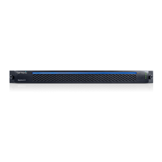
121 Setting the Spectrum X to "diskless" mode on page 84 Spectrum X bezel The Spectrum X bezel provides power and status indicators to quickly assess the status of the device. Figure 4-1: Spectrum X bezel Component Detail Air vents Air vents provide optimum air flow from the internal fans. -
Page 100: Spectrum X Status Leds
Chapter 4: Spectrum X hardware reference Spectrum X status LEDs The Spectrum X status LEDs indicate the status for reference, the Ethernet network connection, and the SDI I/O cards. Figure 4-2: Spectrum X status LED states Spectrum X front panel The Spectrum X front panel provides access to drives and other components. -
Page 101: Spectrum X Control Panel
Spectrum X front panel Spectrum X control panel The Spectrum X control panel provides basic system status. Figure 4-4: Spectrum X control panel Button/Indicator Description System ID button with The identification button can be used to locate a integrated LED particular system within a rack. -
Page 102: Spectrum X Rear Panel
Drive activity LED Indicates drive activity. Spectrum X rear panel The Spectrum X rear panel provides network connectivity, serial connections, and audio and video I/O connections. Figure 4-5: Spectrum X rear panel Component... - Page 103 Ethernet cable or better for these network interfaces. For lengths between 37m and 100m, or greater, use CAT 6a. VGA port Use only if instructed by Harmonic technical support to do so. RS-232 serial For Service only USB ports Use only if instructed by Harmonic technical support to do so.
-
Page 104: About Enhanced Channel Mode
Spectrum X supports UHD playout and record. Note that both SDI cards on the Spectrum X are used to play or record one channel of UHD. In order to configure a UHD player, in SystemManager, the Channel Configuration setting on the I/O Module Properties page for your Spectrum X must be set to Ultra. -
Page 105: Spectrum X Channel Mode Configurations
For instructions on creating a UHD player, see the SystemManager User Guide. Spectrum X channel mode configurations The Spectrum X offers eight DIN 1.0/2.3 connectors for video input and output. The connector configurations vary according to Standard Channel mode and Enhanced Channel mode. -
Page 106: Spectrum X Sdi I/O Connectors: Standard Channel Mode
The Spectrum X uses DIN 1.0/2.3 connectors for its SDI I/O connections. The connectors have specific functionality when the Spectrum X is in standard channel mode. Refer to the figure and the table for information on the different SDI I/O connections when the Spectrum X is in standard channel mode. -
Page 107: Spectrum X Sdi I/O Connectors: Enhanced Channel Mode
The Spectrum X uses DIN 1.0/2.3 connectors for its SDI I/O connections. The connectors have specific functionality when the Spectrum X is in enhanced channel mode. Refer to the figure and the table for information on the different SDI I/O connections when the Spectrum X is in enhanced channel mode. - Page 108 Chapter 4: Spectrum X hardware reference Figure 4-7: Spectrum X SDI I/O connectors: enhanced channel Component Description External Input 1/ Use for video input or External Key input 1. Refer to “Enabling External Key Input Enhanced Channel mode” in the Harmonic SystemManager User Guide for instructions on configuring Enhanced Channel mode to enable Key/Fill.
-
Page 109: Spectrum X Sdi I/O Connectors: Uhd Mode
The Spectrum X uses DIN 1.0/2.3 connectors for its SDI I/O connections. The connectors have specific functionality when the Spectrum X is in UHD channel mode. Refer to the figure and the table for information on the different SDI I/O connections when the Spectrum X is in UHD mode. -
Page 110: High Density Dsub 60 Connector Pinout
Chapter 4: Spectrum X hardware reference Component UHD link Output, Secondary or HD/SD Output: B branded NOTE: “HD/SD-branded” refers to Independent Branding mode. NOTE: For input of non-UHD content, use I/O 2. High Density DSUB 60 connector pinout The DSUB 60 connector provides connections for RS-422, GPIO, reference video, and multi-function I/O. -
Page 111: 10 Gb Fiber Optic Port Led States
Spectrum X rear panel LED/State Condition Speed: green Network traffic at 1 Gbps Speed: yellow Network traffic at 100 Mbps Speed: off No link CAUTION: If two power supplies are used, they must be of the same type and have the same maximum output power. -
Page 112: Power Supply Led States
CAUTION: If two power supplies are used, they must be of the same type and have the same maximum output power. About Spectrum X storage The Spectrum X in internal storage configuration provides four hot-swappable disk drives in a 3+1 RAID set. Refer to the following table for supported RAID configurations. -
Page 113: Spectrum X Drive Leds
About Spectrum X storage Table 4-9: Spectrum X RAID configurations Drives RAID set Capacity per drive Storage capacity 4 SAS 6 TB 18 TB 4 SAS 4 TB 12 TB 4 SAS 2 TB 6 TB NOTE: No other disk drive configurations are supported. -
Page 114: Breakout Cable
Chapter 4: Spectrum X hardware reference Breakout cable Harmonic provides a breakout cable for use with the DSUB 60 connector, which provides six RS-422 connectors, one GPIO connector, a Reference In connector, and four multi-function I/O (MFIO) connectors. Figure 4-13: Breakout cable overview... - Page 115 Reference In Use for Reference video For instructions on configuring a serial connection to control graphics, see "Configuring a Spectrum X and ChannelPort Channel" in the Harmonic SystemManager User Guide. For instructions on configuring GPIO, see "Configuring Spectrum X GPIO Triggers" in the Harmonic SystemManager User Guide.
-
Page 116: Partial Breakout Cable
Chapter 4: Spectrum X hardware reference Partial breakout cable Harmonic provides a partial breakout cable for use with the DSUB 60 connector, which includes one RS-422 connector, one GPIO connector, a Reference In connector, and four multi-function I/O (MFIO) connectors. -
Page 117: Reference Breakout Cable
"Attaching Devices and Setting Conversion Options"in the Harmonic SystemManager User Guide. Reference breakout cable Harmonic provides a partial breakout cable for use with the DSUB 60 connector, which includes a Reference In connector and four multi-function I/O (MFIO) connectors. Figure 4-15: Reference breakout cable overview... -
Page 118: Breakout Cable: Rs-422 Connector Pinout
Chapter 4: Spectrum X hardware reference Use the Attach Devices page in SystemManager to configure LTC or AES audio for a connector. For instructions, see "Attaching Devices and Setting Conversion Options" in the Harmonic SystemManager User Guide. Related information Partial breakout cable... -
Page 119: About Rs-422 Grounding
RS422_TS5- RS422_TS5+ About RS-422 grounding Note the Harmonic recommendations regarding RS-422 grounding. • RS-422 uses differential signaling, much like balanced audio. As long as the chassis grounds of the controller and the Spectrum device share a common ground through the AC power connections, no ground connection is needed on the RS-422 cable. -
Page 120: Breakout Cable: Gpio Connector Pinout
With Spectrum 8.2 and later, licensed features for Spectrum systems with Spectrum X are installed on the Spectrum video server regardless of whether the Spectrum X is in internal storage mode or shared storage mode. To view all installed licenses, open the Licensed Features page for your Spectrum video server in SystemManager. -
Page 121: Spectrum X Specifications
• 2 - 4 video outputs per channel with independently configurable up/ configuration) down/cross-conversion UHD channel Both SDI cards on the Spectrum X are required to play or record one (depends on channel of UHD configuration) • 8 inputs per channel •... - Page 122 Chapter 4: Spectrum X hardware reference Specification Details • 1080i @ 25, 29.97 fps • 720p @ 50, 59.94 fps HD 3G 1080p @ 50, 59.94 fps Ultra HD (UHD) • 2160p @ 50, 59.94 fps, Interleaved, Square Division •...
- Page 123 Spectrum X specifications Table 4-29: SD-SD Aspect Ratio Converter (ARC) Specification Detail RP-186 AFD • 16:9 SD to 4:3 Letterbox (Vertical Decimation) SMPTE-2016, ATSC • 16:9 SD to Full Screen (Horizontal Interpolation) A/53 • 16:9 SD to Crop 14:9 (Vertical Decimation, Horizontal Interpolation)
- Page 124 Chapter 4: Spectrum X hardware reference Specification Detail EIA-708 Digital caption data preserved on record and inserted on playout. Onboard Closed Onboard Closed Caption Insertion available as licensed feature; Cheetah, Caption Insertion NCI, and SCC are supported file types. Onboard subtitle Insertion OP47a Onboard Subtitle Insertion available as licensed feature;...
- Page 125 Power with one SDI I/O card, no drives 464 W Table 4-38: Environmental Altitude Maximum temp Maximum temp for Spectrum X in internal for Spectrum X in shared storage mode (four drives storage mode (no drives) installed) 3000m (10K') 30° C 33°...
-
Page 126: Chapter 5: Mediadirector Hardware Reference
The MediaDirector is the core of the Spectrum system, actively managing the flow of data to and from other Spectrum components, including the MediaStore 5000 series storage arrays and real-time I/O modules such as MediaPort 7000, ChannelPort, and Spectrum X. The MediaDirector 2252B includes 12 connections for I/O modules, as well as 10 Gb Ethernet ports for file transfers, SAS connections for storage, and EFS connections. -
Page 127: Mediadirector Bezel
MediaDirector bezel MediaDirector bezel The bezel provides power and status indicators to quickly assess the status of the MediaDirector products. Figure 5-1: MediaDirector bezel Component Detail Air vents Air vents provide optimum air flow from the internal fans. Do not obstruct the air vents. Power indicator This indicator lights when the system is powered on, and also provides a "wink"... - Page 128 Chapter 5: MediaDirector hardware reference Figure 5-2: Front panel buttons Component Description Power button Turns the unit On/Off. For use only if you are unable to use SystemManager to power down the system. Reset button Operates as a momentary switch to complete a “soft” reset of the MediaDirector or MediaCenter.
-
Page 129: Mediadirector Status Leds
MediaDirector status LEDs MediaDirector status LEDs The MediaDirector status LEDs indicate basic information about the system. Figure 5-3: MediaDirector status LEDs MediaDirector 2252B and 2252B-DS rear panel The rear panel for the MediaDirector 2252B and 2252B-DS includes connections for I/O modules, as well as 10 Gb Ethernet ports for file transfers, SAS connections for storage, and EFS connections. - Page 130 Chapter 5: MediaDirector hardware reference Figure 5-5: MediaDirector 2252B-DS rear panel Component Description Boot drive Top bay only Power button/LED This button/LED turns the unit On/Off. If a power cord is attached to the unit and the button is pressed, the LED flashes blue to indicate the unit is transitioning.
-
Page 131: Gb Ethernet Port Status Leds (For System Management)
VGA port For Service only RS-232 serial port For Service only USB ports Do not use unless instructed by Harmonic technical support. MediaPort Ethernet array Use these ports only to connect to MediaPorts, ChannelPorts, and Spectrum X devices. DO NOT use these ports for any other purpose, including plugging directly into a network. -
Page 132: Gb Ethernet Led States (For Efs Connections)
Chapter 5: MediaDirector hardware reference State On with 100 Mbps link 1000 On with 1 Gbps link Figure 5-7: 1 Gb Ethernet port LEDs (green, amber, yellow) LED/State Condition Link/Activity: green 1 Gbps Link/Activity: off No link Speed: amber 1 Gbps Speed: green 100 Mbps Speed: off... -
Page 133: Mediaport Ethernet Array Led States
MediaDirector 2252B and 2252B-DS rear panel MediaPort Ethernet array LED states The MediaPort Ethernet array ports provide access to MediaPort, ChannelPorts, and Spectrum X. Do not use these ports for any purpose other than I/O module connection. Figure 5-9: MediaPort Ethernet array LED states... -
Page 134: 10 Gb Fiber Optic Port Led States
Chapter 5: MediaDirector hardware reference 10 Gb fiber optic port LED states The optional 10 Gb fiber optic ports I/O module ports can be used for SMPTE 2022-6 video. The LEDs provide information on link status, activity, and speed. LED/State Condition Link/Activity: green (blink) Network activity... -
Page 135: Mediadirector 2251B Rear Panel
MediaDirector 2251B rear panel LED state Condition Amber, solid AC power is lost or a power supply is shut down. CAUTION: If two power supplies are used, they must be of the same type and have the same maximum output power. MediaDirector 2251B rear panel The rear panel for the MediaDirector 2251B includes 6 connections for I/O modules, as well as 10 Gb Ethernet ports for file transfers, SAS connections for storage, and EFS connections. - Page 136 Component Description MediaPort Ethernet array Use these ports only to connect to MediaPorts, ChannelPorts, and Spectrum X devices. DO NOT use these ports for any other purpose, including plugging directly into a network. Power supplies (0, 1 from Two power supplies, each including an...
-
Page 137: Mediadirector Specifications
1 Gb Ethernet 6 ports for EFS connections only Table 5-5: Timing Reference Per MediaPort/ The MediaDirector can support multiple timing standards on a single ChannelPort/ system. Reference is handled by MediaPorts independently. Spectrum X/ Spectrum System 8.4 Installation Guide... - Page 138 Chapter 5: MediaDirector hardware reference Table 5-6: Dimensions Weight (including rack rails) L x H x W (bezel attached, rack mountable per EIA-310 specification) 43.3 lbs 30.75" x 3.5" x 17.25" Table 5-7: MediaDirector power Specification Detail Power (max) 231 W Voltage 90 to 132V and 180 to 264V Frequency...
-
Page 139: Chapter 6: Mediacenter 2200B Hardware Reference
The MediaCenter 2200B provides a compact media server solution for up to 24 channels, and up to 32- TB of usable storage. Up to 10 Spectrum MediaPorts, ChannelPorts, or Spectrum X devices can be connected to the MediaCenter for real-time ingest and playout of video and audio content. -
Page 140: Mediacenter 2200B Bezel
Chapter 6: MediaCenter 2200B hardware reference Related information MediaCenter 2200B specifications on page 148 MediaCenter 2200B bezel The bezel provides power and status indicators to quickly assess the status of the device. Figure 6-1: MediaCenter 2200B bezel Component Detail Air vents Air vents provide optimum air flow from the internal fans. - Page 141 MediaCenter 2200B bezel Figure 6-2: Front panel buttons Component Description Power button Turns the unit On/Off. For use only if you are unable to use SystemManager to power down the system. Reset button Operates as a momentary switch to complete a “soft” reset of the MediaDirector or MediaCenter.
-
Page 142: Mediacenter 2200B Status Leds
Chapter 6: MediaCenter 2200B hardware reference MediaCenter 2200B status LEDs The MediaCenter 2200B status LEDs indicate basic system status. Figure 6-3: MediaCenter 2200B status LEDs MediaCenter 2200B and 2200B-DS rear panel The MediaCenter 2200B and 2200B-DS rear panels include connections for I/O modules, external storage, and 10 Gb Ethernet ports for file transfers. - Page 143 MediaCenter 2200B and 2200B-DS rear panel Figure 6-5: MediaCenter 2200B rear panel Component Description Boot drive Top bay only Power button/LED This button/LED turns the unit On/Off. If a power cord is attached to the unit and the button is pressed, the LED flashes blue to indicate the unit is transitioning.
-
Page 144: Gb Ethernet Port Status Leds (For System Management)
VGA port For Service only RS-232 serial port For Service only USB ports Do not use unless instructed by Harmonic technical support. BMC port For Service only 10 Gb optical SFP (optional) If installed, use these port for file transfers or communication with a public network. -
Page 145: 10 Gb Ethernet Port Led States
MediaCenter 2200B and 2200B-DS rear panel LED/State Condition Link/Activity: green 1 Gbps Link/Activity: off No link Speed: amber 1 Gbps Speed: green 100 Mbps Speed: off Inactive or 10 Mbps 10 Gb Ethernet port LED states The 10 Gb Ethernet ports can be used for file transfers. The LEDs provide link, activity, and link speed status. -
Page 146: Mediaport Ethernet Array Led States
Network traffic at 100 Mbps or no activity MediaPort Ethernet array LED states The MediaPort Ethernet array ports provide access to MediaPort, ChannelPorts, and Spectrum X. Do not use these ports for any purpose other than I/O module connection. Figure 6-9: MediaPort Ethernet array LED states... -
Page 147: About Mediacenter 2200B Storage
About MediaCenter 2200B storage LED state Condition Green, solid A valid AC source is connected to the power supply, and the power supply is operational. Green (1 Hz blink) AC is present, but the power switch on the front panel is off or in a cold redundant state due to low system power load. -
Page 148: Mediacenter 2200B Drive Leds
Chapter 6: MediaCenter 2200B hardware reference MediaCenter 2200B drive LEDs Each drive includes a status and activity LED, which provide information on the RAID set state, drive usage or faults, and a wink capability. Figure 6-12: Drive LEDs Table 6-2: Status LED (amber) State Description Solid... - Page 149 2 four-port mini SAS HD connectors (SFF-8644) Table 6-6: MediaPort Ethernet array Specification Details Private 1 Gb 10 ports available for MediaPort/ChannelPort/Spectrum X connectivity. Ethernet Table 6-7: Reference Per MediaPort/ The MediaCenter can support multiple timing standards on a single ChannelPort/ system.
-
Page 150: Chapter 7: Mediaport 7000 Series Hardware Reference
Chapter 7 MediaPort 7000 series hardware reference The MediaPort 7000 series includes hot-swappable modules, which provide SDI and GPIO connections as well as Gigabit Ethernet connectivity. MediaPort 7000 series modules can be licensed to record and play a variety of codecs, perform up, down, and cross conversion, record proxies, as well as support Playlist Control, onboard Media Fetch, onboard subtitle insertion, and onboard closed caption insertion. -
Page 151: Mediaport 7000 Bezel
MediaPort 7000 bezel • Simulcast for every channel, where SD-only channels include 2 identical outputs, and HD-capable channels include 2 independently-configurable outputs. An HD video channel can be presented in both 720p and 1080i. • A proxy option that enables simultaneous generation of both low- and high-resolution clips during recording. -
Page 152: About The Port Status Display
If the current clip does not contain any timecode, then the front panel reports timecode starting from 00:00:00:00. This behavior follows the conventions used by other Harmonic tools, such as ClipTool. •... -
Page 153: Power Supply Led States
AC In connector. If one supply fails, the load is transferred to the remaining supply without interruption of service. To take full advantage of the redundant supplies, Harmonic recommends that you use separate, isolated power sources for each AC input. -
Page 154: Mediaport 7000 Series Module Rear Panel
Chapter 7: MediaPort 7000 series hardware reference MediaPort 7000 Series module rear panel The MediaPort 7000 series modules share a common rear panel view. Figure 7-4: MediaPort 7000 series module rear panel Component Description HD/SD SDI IN Channel A Use for SDI video input on Channel A. HD/SD SDI OUT Channel A Use for SDI video output on Channel A. - Page 155 MediaPort 7000 Series module rear panel Component Description LTC IN Channel A Use these connectors for an analog LTC (longitudinal timecode) signal: two input (IN) LTC OUT Channel B and two output (OUT). When LTC is present at the IN port and a Player has been configured LTC IN Channel B to record LTC, LTC timecode will be embedded LTC OUT Channel B...
-
Page 156: Mediaport 7000 Gpio Signal Assignments
On both the MediaPort 7000 and the ChannelPort, the left-most RJ-45 connector is wired for two channels (Ch 0 and Ch 1). Harmonic supplies an RJ-45/ DB-9 splitter cable, which provides the Channel 0 on one DB-9 and the Channel 1 signals on the other. -
Page 157: Rj-45/Db-9 Splitter Cable Pinout
RJ-45 port. This cable splits the two sets of signals out to two DB-9 connectors. Use the Harmonic RJ45/DB-9 splitter cable to interface with controllers (or cables) using standard SMPTE/EBU ES bus wiring connections. This adapter converts the RJ45 connections on the back of the MediaPorts to standard SMPTE/EBU ES Bus. -
Page 158: About Rs-422 Grounding
Harmonic RJ45/DB-9 Splitter Cable to Standard RS-422 extension cable • Harmonic RJ45/DB-9 Splitter Cable to Automation System adapter cable NOTE: Harmonic does not provide RS-422 extension cables or RJ45 (Ethernet) extension cables. About RS-422 grounding Make sure to follow grounding guidelines for RS-422. -
Page 159: About Mediaport 7000 Support For Ac-3 And Dolby E
The audio samples will be “passed through” as received with no attempt at realignment. For instructions on adding audio tracks to players, refer to “Adding Audio Tracks” in the Harmonic SystemManager User Guide. - Page 160 Chapter 7: MediaPort 7000 series hardware reference Model H.264 MPEG-2 AVC-Intra AVC-Intra VC-3 rec/ ProRes proxy rec/play DVCPRO play play play rec/play MIP-7601 Table 7-2: MediaPort 7000 series license options Product Up, Down, MPEG-2 DV, AVC- VC-3 Cross DVCPRO Intra Convert, rec/play HD/SD...
- Page 161 MediaPort 7000 series module and license options Product ID Description MPU-7000-M2R License upgrade to add MPEG-2 RECORD to any MIP-760X MediaPort MPU-7000-S2H License upgrade to add HD SUPPORT to any SD MIP-7X0X MPU-7000-VC3P License upgrade to add VC-3 PLAY to any MIP-7X0X or ChannelPort MPU-7000-VC3R License upgrade to add VC-3 REC to any HD MIP-7X0X MPU-7100-D2M...
-
Page 162: Mediaport 7000 Module Specifications
Chapter 7: MediaPort 7000 series hardware reference Product ID Description AUTO-EXPORT Auto-export to Harmonic MediaGrid license for all channels of the MediaCenter and MediaDirector respectively. MediaPort 7000 module specifications The MediaPort 7000 series chassis can accommodate two modules. NOTE: For video codec and audio format support, see Spectrum Media and Wrapper Formats. - Page 163 MediaPort 7000 module specifications Table 7-10: Cross conversion Specification Detail Cross conversion 720p to 1080i 1080i to 720p Table 7-11: Video raster Specification Detail 720x486i (29.97fps) • 720x576i (25 fps) • 1280x720 (50 and 59.94 fps) • 1920x1080i (25 and 29.97 fps) •...
- Page 164 Chapter 7: MediaPort 7000 series hardware reference Specification Detail EIA-708 Digital caption data preserved on record and inserted on playout. Onboard Closed Onboard Closed Caption Insertion available as licensed feature; Cheetah, Caption Insertion NCI, and SCC are supported file types. Table 7-17: Onboard subtitle Insertion Specification Detail...
-
Page 165: Mediaport 7000 H.264 Proxy Options
MediaPort 7000 H.264 proxy options Specification Detail CISPR 22 Class A Australia, New Zealand, EU CNS 13438 Class A Taiwan ICES-003 Class A Canada En 55022 Class A KN22 Class A Korea Table 7-23: Dimension Specification Detail Height 4.4 cm (1.75”) 1RU Width 44.4 cm (17.15”) Chassis only, IEC rack compliant Depth... - Page 166 Chapter 7: MediaPort 7000 series hardware reference Table 7-26: Video bit rate Specification Detail 600 Kbps – 3.0 Mbps User configurable Table 7-27: Chroma sampling Specification Detail 4:2:0 Table 7-28: Audio encoding Specification Detail AAC-LC 0-8 two-channel pairs (up to 16 channels) Table 7-29: Audio bit rate Specification Detail...
- Page 167 MediaPort 7000 H.264 proxy options Table 7-35: Logo/watermark Specification Detail User-supplied PNG with alpha Position selectable by user Table 7-36: Link to hi-res Specification Detail SMPTE 330M Via parent UMID Spectrum System 8.4 Installation Guide...
-
Page 168: Chapter 8: Channelport Module Hardware Reference
Chapter 8 ChannelPort module hardware reference The ChannelPort 8100 and 8200 modules support clip playout, channel branding, key/fill input, emergency alert systems, and cuts-only switching between live inputs and prerecorded clips. Each ChannelPort module provides a “channel” or “channels” capable of playing and processing control commands. -
Page 169: About Enhanced Channel Mode
• Use an external device to generate key or fill graphics, and overlay the graphics onto the Spectrum X or the ChannelPort output video, along with graphics generated by the Spectrum X or the ChannelPort. Note that when the Spectrum X or the ChannelPort module is in Enhanced Channel mode, the functionality of some I/O connectors will change based on your I/O Configuration selection in the SystemManager or Spectrum Management. -
Page 170: Channelport 8100 Channel Mode Configurations
Chapter 8: ChannelPort module hardware reference ChannelPort 8100 channel mode configurations The ChannelPort 8100 includes six BNC connectors for SDI video input and output: two for input and four for output. The BNC connector configurations vary according to Standard Channel mode and Enhanced Channel mode. -
Page 171: About Channelport Modules
I/O 8 Out, Secondary About ChannelPort modules Harmonic offers two ChannelPort modules with options to support various video formats and a variety of add-on functionality. Each module can be installed in the MediaPort 7000. Additional licensed, add-on functionality for each module is available as described in the section on license options. -
Page 172: Channelport Module Rear Panel
“Enabling Enhanced Channel mode” in the Harmonic SystemManager User Guide for instructions on configuring Enhanced Channel mode to enable Key/Fill. Refer to the Spectrum X and ChannelPort Template Authoring Guide for information on External Key/Fill. Video Output (Primary) Use for primary video output or for HD-branded output when in Independent Branding mode. - Page 173 Blue, blinking: Indicates wink state is on. For information on changing the wink state, refer to “Changing the ChannelPort wink state” in the Harmonic SystemManager User Guide. GPIO Connector This connector can be used for player or graphics control, or for EAS connection. See "GPIO connector signal assignments"...
-
Page 174: Channelport 8100 Rear Panel: Standard Channel Mode
Use for primary video output or for HD-branded (Primary) output when in Independent Branding mode on Channel A. Refer to “Configuring a ChannelPort channel” in the Harmonic SystemManager User Guide for instructions on configuring Independent Branding mode. Video Output Channel A... - Page 175 Blue, blinking: Indicates wink state is on. For information on changing the wink state, refer to “Changing the ChannelPort wink state” in the Harmonic SystemManager User Guide. GPIO Connector This connector can be used for player or graphics control, or for EAS connection. See “GPIO connector signal assignments”...
-
Page 176: Channelport 8200 Rear Panel: Enhanced Channel Mode
Key Input 1 Refer to “Enabling Enhanced Channel mode” in the Harmonic SystemManager User Guide for instructions on configuring Enhanced Channel mode to enable Key/Fill. Refer to the Spectrum X and ChannelPort Template Authoring Guide for information on External Key/Fill. - Page 177 Use for video input, secondary video output, or for Output (Secondary) SD-branded output when in Independent Branding mode. Refer to “Configuring a ChannelPort channel” in the Harmonic SystemManager User Guide for instructions on configuring Independent Branding mode. Video Output (Primary)
-
Page 178: Channelport 8200 Rear Panel: Standard Channel Mode
Blue, blinking: Indicates wink state is on. For information on changing the wink state, refer to “Changing the ChannelPort wink state” in the Harmonic SystemManager User Guide. GPIO Connector This connector can be used for player or graphics control, or for EAS connection. See “GPIO connector signal assignments”... - Page 179 Use for secondary video output or for SD-branded output on Channel A when in Independent Channel A Branding mode. Refer to “Configuring a ChannelPort channel” in the Harmonic SystemManager User Guide for instructions on configuring Independent Branding mode. Video Output (Primary)
- Page 180 Blue, blinking: Indicates wink state is on. For information on changing the wink state, refer to “Changing the ChannelPort wink state” in the Harmonic SystemManager User Guide. GPIO Connector This connector can be used for player or graphics control, or for EAS connection. See “GPIO connector signal assignments”...
-
Page 181: About Mediaport 7000 And Channelport Timing
About MediaPort 7000 and ChannelPort timing NOTE: “HD/SD-branded” refers to Independent Branding mode. Related information About MediaPort 7000 and ChannelPort timing on page 156 GPIO/RS-422 connector signal assignments on page 181 About MediaPort 7000 and ChannelPort timing Timing works the same way on both MediaPort 7000 and ChannelPort modules. If reference VITC is present on the timing input of a MediaPort or ChannelPort, it will provide the timecode information to any Players associated with that MediaPort or ChannelPort, unless it is overridden by a LTC connection on the Spectrum video server. -
Page 182: Serial Control Connections For A Mediaport 7000 And A Channelport
On both the MediaPort 7000 and the ChannelPort, the left-most RJ-45 connector is wired for two channels (Ch 0 and Ch 1). Harmonic supplies an RJ-45/ DB-9 splitter cable, which provides the Channel 0 on one DB-9 and the Channel 1 signals on the other. -
Page 183: Rj-45/Db-9 Splitter Cable Pinout
RJ-45 port. This cable splits the two sets of signals out to two DB-9 connectors. Use the Harmonic RJ45/DB-9 splitter cable to interface with controllers (or cables) using standard SMPTE/EBU ES bus wiring connections. This adapter converts the RJ45 connections on the back of the MediaPorts to standard SMPTE/EBU ES Bus. -
Page 184: About Rs-422 Grounding
NOTE: Due to changes in the license structure, ChannelPort licenses issued for releases 7.0 and 7.1 will not have full graphics capabilities when used with release 7.2 or later. To correct this problem, contact Harmonic Technical Assistance Center to request a new ChannelPort license key. - Page 185 License options Product Up, Down, MPEG- AVC- VC-3 ProRes Cross 2 play DVCPRO Intra play play Convert, play play HD/SD Simulcast AVCI SPL- PRORES Table 8-10: Additional ChannelPort module licensed features Product ID Description CPL-8000-EAS Onboard emergency alert system support for ChannelPort, per channel CPL-COMBINED- License upgrade to enable ChannelPort combined channel mode.
-
Page 186: Channelport Specifications
SPL-AVCI-PLAY AVC-Intra playout upgrade license for one ChannelPort or MediaPort 7000 module (two channels). AUTO-EXPORT Auto-export to Harmonic MediaGrid license for all channels of the MediaCenter and MediaDirector respectively. ChannelPort specifications Find ChannelPort specifications here. Each MediaPort 7000 series chassis can accommodate two ChannelPort modules with up to two independent playout channels per module. - Page 187 ChannelPort specifications Table 8-12: Video I/O Specification Details SD: SMPTE 259M 8100 modules: 6 75 ohm BNC female connectors HD: SMPTE 292M 8200 modules: 8 DIN 1.0/2.3 connectors Note: The SMPTE specifications refer to BNC connectors only. However, the DIN connectors on the 8200 module are electrically equivalent to the specifications.
- Page 188 Chapter 8: ChannelPort module hardware reference Table 8-15: Video raster Specification Details 720x486i (29.97fps) 720x576i (25 fps) 1280x720p (50 and 59.94 fps) 1920x1080i (25 and 29.97 fps) 1920x1080p (25 and 29.97 fps carried as psf in HD-SDI*) Table 8-16: Audio channels Specification Details SMPTE 272M...
- Page 189 ChannelPort specifications Table 8-20: Onboard subtitle insertion Specification Details OP47a Onboard Subtitle Insertion available as licensed feature; STL, PAC, and 890 are supported file types. SMPTE-2031 Table 8-21: Ancillary data Specification Details Up to 6 lines (configurable) preserved. Line 21 caption data saved automatically VANC Up to 6000 bytes (configurable) preserved per frame...
- Page 190 Chapter 8: ChannelPort module hardware reference Specification Details VCCI Class A Japan CISPR 22 Class A Australia, New Zealand, EU CNS 13438 Class A Taiwan ICES-003 Class A Canada En 55022 Class A KN22 Class A Korea...
-
Page 191: Chapter 9: Mediastore 5100 And 5000 Series Hardware Reference
Chapter 9 MediaStore 5100 and 5000 series hardware reference The MediaStore 5100and 5000 series is a network storage device that employs Serial-attached SCSI (SAS) host bus adapters (HBA) to connect to a MediaDirector. The MediaStore 5100/5000 series is based on a storage subsystem together with a set of plug-in modules. •... -
Page 192: About The Mediastore 5000 Series
Chapter 9: MediaStore 5100 and 5000 series hardware reference About the MediaStore 5000 series Using 6 Gb/s SAS connections and the MediaDirector 2252B or 2251B, up to four MediaStore 5000 series can be connected together. A second MediaDirector can be added for Extended File Sharing. The MediaStore 5000 series include the following features: •... -
Page 193: Mediastore 5100 And 5000 Series Disk Carrier Module
MediaStore 5100 and 5000 series disk carrier module MediaStore 5100 and 5000 series disk carrier module A drive carrier module houses a single 5/8-inch high, 2.5-inch disk drive. Each drive carrier provides excellent thermal conduction, radio frequency and electro-magnetic induction protection and affords maximum protection for the drive. -
Page 194: Mediastore 5100 And 5000 Series Drive Carrier Components
Chapter 9: MediaStore 5100 and 5000 series hardware reference MediaStore 5100 and 5000 series drive carrier components The front of a drive carrier module consists of an anti-tamper lock, a drive latch, a Drive Status LED and Drive Activity LED. Figure 9-3: Front of drive carrier module Table 9-1: Drive carrier components Component... -
Page 195: Mediastore 5100 And 5000 Series: Drive Carrier Led States
MediaStore 5100 and 5000 series drive carrier components Drive activity LED Drive status LED Associated operator Status (green) (amber) panel LED Blink None Drive installed and operational Solid Blink (1 sec on/1 sec None SAS identity set off) Solid Solid Logical fault (amber) SAS device fault bit Solid... -
Page 196: Mediastore 5100 And 5000 Series Operator Panel Components
Chapter 9: MediaStore 5100 and 5000 series hardware reference MediaStore 5100 and 5000 series operator panel components The operator panel provides a number of LEDs to help with troubleshooting. Figure 9-4: MediaStore 5100/5000 series operator panel Component Descriptions Alarm Silence The Operators Panel incorporates an Audible Alarm that Button indicates when a fault state is present. - Page 197 MediaStore 5100 and 5000 series operator panel components Component Descriptions Audible Alarm The Audible Alarm can be activated for a variety of reasons. Refer to “MediaStore 5100/5000 series audible (behind panel) alarms” for additional details. Thermal Sensor The Operator Panel Thermal Sensor is on the outside the MediaStore and connects to another thermal sensor on (behind panel) the midplane of the MediaStore.
-
Page 198: Setting The Unit Id Number
I/O module and will appear in the Unit ID Display when the MediaStore is next powered • Harmonic recommends that you set the Unit ID of the first MediaStore in your Spectrum system to “01” and to increase Unit ID by one for each additional MediaStore. -
Page 199: Mediastore 5100 And 5000 Series Rear Panel
MediaStore 5100 and 5000 series rear panel 4. When the right-hand digit begins to flash, press the Alarm Silence Button to change the number, or press the button for five seconds to select “00.” MediaStore 5100 and 5000 series rear panel The MediaStore rear panel includes replaceable power cooling modules and I/O modules. -
Page 200: Mediastore 5100 Series I/O Module Components
Chapter 9: MediaStore 5100 and 5000 series hardware reference Component Description I/O Modules The MediaStore contains two I/O Modules for interfacing to additional MediaStores via SAS connection. Both modules are the same (mechanically and electronically). Each module includes three SAS ports and Status LEDs. The Primary I/O Module is installed in the top bay •... -
Page 201: Mediastore 5000 Series I/O Module Components
NOTE: The MediaDirector 2252B/2251B requires a different SAS cable than previous MediaDirector models. To make sure you have the correct SAS cable, contact your Harmonic sales representative. MediaStore5100: I/O module status LEDs The I/O modules include status LEDs for help with troubleshooting. - Page 202 NOTE: The MediaDirector 2252B/2251B requires a different SAS cable than previous MediaDirector models. To make sure you have the correct SAS cable, contact your Harmonic sales representative. MediaStore5000 series: I/O module status LEDs The I/O modules include status LEDs for help with troubleshooting.
-
Page 203: Mediastore 5100 And 5000 Series Power Cooling Modules (Pcms)
MediaStore 5100 and 5000 series rear panel Component Status Definition I/O Module Green (Solid) Power Green (Blink) Configuration error Clear I/O Module Amber Fault Condition Fault Clear Normal MediaStore 5000 series: SAS link activity LEDs During normal operations, the three SAS connections on an I/O module are measured for Link Activity. Figure 9-12: MediaStore 5000 series SAS link activity LEDs Indicator Status... - Page 204 Chapter 9: MediaStore 5100 and 5000 series hardware reference Refer to “Power cooling module replacement” in the MediaStore Component Replacement Guide for instructions. PCM voltage operating ranges are nominally 115V or 230V AC, selected automatically. MediaStore 5100 and 5000 series: power cooling module components PCMs include power supply status LEDs, power button, AC In connector, power supply retainer, as well as a latch and handle.
- Page 205 MediaStore 5100 and 5000 series rear panel MediaStore 5100 and 5000 series: power cooling module status LEDs Under normal conditions, the Power status LED is illuminated green and all other LEDs are off. If a problem occurs, the relevant LED lights amber. Figure 9-14: PCM status LEDs Table 9-4: PCM symbols and definitions Symbol...
-
Page 206: About Drive Start Up
Chapter 9: MediaStore 5100 and 5000 series hardware reference About drive start up Unless otherwise selected during installation, all drives in the MediaStore will automatically start their motors upon power-up. If this has not occurred, there may be a power problem (an alarm and power fault indication would normally be active). -
Page 207: Mediastore5100 And 5000 Series Troubleshooting And Maintenance
MediaStore 5100 and 5000 series operator panel components on page 196 About data security In order to prevent loss of data, Harmonic recommends that you follow some data security guidelines when handling a disk drive. • Each MediaStore contains up to 24 removable disk drives. Disk units are fragile. Handle them with care, observe static electricity precautions, and keep them away from strong magnetic fields. -
Page 208: Dealing With Hardware Faults
Chapter 9: MediaStore 5100 and 5000 series hardware reference Dealing with hardware faults Be sure to take certain precautions when dealing with hardware faults. Before you begin DANGER: If a MediaStore is powered up and you remove any module, replace it immediately. - Page 209 MediaStore5100 and 5000 series troubleshooting and maintenance muted, it continues to sound with short intermittent bleeps to indicate that a problem still exists. It will be silenced when all problems are cleared. The Alarm Silence Button can be used to test the LEDs on the Operators Panel. When the Alarm Silence Button is pressed and held, all LEDs will be illuminated if there are no faults present.
- Page 210 Chapter 9: MediaStore 5100 and 5000 series hardware reference Status Severity Alarm Drive power control fault Warning—no loss of drive power Drive power control fault Fault—critical—loss of drive power Troubleshooting subsystem recognition problems Follow this procedure when the MediaDirector does not recognize the MediaStore subsystem. 1.
-
Page 211: Troubleshooting Thermal Monitoring And Control Faults
MediaStore5100 and 5000 series troubleshooting and maintenance Symptom Cause Action Audible alarm Thermal condition that could Disconnect the PCM from the main cause PCM overheating power. Remove and then re-install the PCM. If the problem persists, replace the PCM. Refer to the Spectrum MediaStore Component Replacement Guide for instructions on removing and re- installing the PCM. -
Page 212: Overview Of Proactive Drive Alarming And Removal
Chapter 9: MediaStore 5100 and 5000 series hardware reference • Check that the local ambient environment temperature is below the given specifications. • Check the installation for any airflow restrictions at either the front or rear of the MediaStore. A minimum gap of 25 mm at the front and 50 mm at the rear is recommended. - Page 213 MediaStore5100 and 5000 series troubleshooting and maintenance • Persistent Login Failures: A warning alarm (yellow) is generated for any drive that experiences persistent Login failures. If a Spectrum server cannot log in to a disk for more than five seconds, that drive will be temporarily removed from the RAID set (subject to the conditions mentioned above), but no Spectrum server in the RAID set will attempt to start a rebuild on the drive's RAID set, even if a hot spare is available.
-
Page 214: About Bad-Block Auto-Repair
Chapter 9: MediaStore 5100 and 5000 series hardware reference cycled. When this condition is detected, the disk will be failed, regardless of any of the requisite conditions mentioned previously. In extreme circumstances, this may cause the MediaDirector to shut down its file system, stopping all playback and recording on that Spectrum server (but not affecting other Spectrum servers in an EFS system.) The drive will be automatically bypassed, and an alarm message will be generated instructing the operator to remove and reinsert the drive. -
Page 215: Performing Grounding Checks
MediaStore5100 and 5000 series specifications Notes about proactive drive alarming and removal Spectrum provides proactive drive alarming and removal for drives in the system. Alarms are generated for Warning level situations in addition to alarms for Critical and Failure level situations. - Page 216 Chapter 9: MediaStore 5100 and 5000 series hardware reference Specification Detail Total Capacity 24 drives Table 9-8: MediaStore 5000 series General Information Specification Detail External Interface 6 Gbps SAS ports (3 per I/O Module; 4 External links per port) Supported Hosts Single/dual active/dual independent bridge Total Capacity 16 –...
- Page 217 MediaStore5100 and 5000 series specifications Specification Detail Power consumption: 388 W at 240 VAC 24 drive model 396 W at 110 VAC Voltage 100 – 240 VAC rated Frequency 50 – 60 Hz Table 9-13: Safety Specification Detail UL 60950-1 2nd Information Technology Equipment –...
-
Page 218: Chapter 10: Mediastore 7200 Series Hardware Reference
Hot-swappable high-performance 2, 4, or 6 TB SAS hard disk drives. • Serial-attached SCSI (SAS) connections. NOTE: There are no user-serviceable parts on the MediaStore7200 series. Harmonic provides either 1 meter or 3 meter SAS cables to connect the MediaStore 7200 to the MediaCenter. -
Page 219: About The File System Configuration For Mediacenter 2200B With Mediastore 7200
About the file system configuration for MediaCenter 2200B with MediaStore 7200 About the file system configuration for MediaCenter 2200B with MediaStore 7200 The available file system configurations for the MediaCenter 2200B with a MediaStore 7200are described here. Table 10-1: MediaCenter 2200B (12 drives) with the MediaStore 7224 (24 drives) # Drives RAID Set Capacity per Drive... - Page 220 Chapter 10: MediaStore 7200 series hardware reference Component Description Control panel Displays power, temperature, fan, and system status LED indicators. System alarm mute Unused (alarm disabled). button Bezel LED control Powers the light bar on the bezel. connector Drive numbering Drives are numbered from 1-24, starting with the top left drive.
-
Page 221: Control Panel Indicators
Control panel indicators Control panel indicators The control panel provides LED indicators for power, system status, temperature, and fans. Figure 10-3: control panel State Description Power Blue Power is being supplied to both power supply units. Power supply fault detected. Power is off. -
Page 222: Disk Drive Led Indicators
Chapter 10: MediaStore 7200 series hardware reference Disk drive LED indicators Each disk drive has an Activity LED and a Status LED. Figure 10-4: MediaStore 7200 disk drive LED indicators Table 10-3: MediaStore 7200 disk drive LED indicators Drive State Activity LED (Blue) Status LED (Red) Drive is powered on... -
Page 223: Rear Panel Components
Rear panel components Rear panel components The rear panel includes dual redundant power supplies and SAS expander modules. Figure 10-5: MediaStore 7200 rear panel Component Description Serial port for remote Do not use. power on/off Expander modules Provides SAS I/O ports. May be replaced in the event of a failure. -
Page 224: Power Supply Unit Led Indicators
Chapter 10: MediaStore 7200 series hardware reference Power supply unit LED indicators Each power supply module has AC, DC, and Warning LED indicators. Figure 10-6: MediaStore 7200 power supply unit LED indicators PSU state AC LED DC LED Warning LED PSU normal, AC Solid Solid... - Page 225 MediaStore 7200 series specifications Specification Detail Depth 534.2 mm (21.03”) Height 173.8 mm (6.8”) , 4 RU Weight (with power 26 kg (57.3 lbs) supplies; without rails or disks) Table 10-7: Environmental Specification Detail Operating Temperature range: 0° to 35° C environment Humidity: 20% to 80% Table 10-8: Power...
-
Page 226: Appendix A: Harmonic Technical Assistance Center Contact Information
Appendix A Harmonic Technical Assistance Center contact information A list of phone numbers, e-mail addresses, and important links for the Harmonic Technical Assistance Center (TAC). Table A-1: Harmonic Technical Assistance Center phone numbers and email addresses Region Telephone Technical Email... -
Page 227: Harmonic Corporate Contact Information
Useful information for Harmonic technical support In order to expedite diagnosis and remediation, please gather helpful information about your Spectrum system as well as your SystemManager platform before contacting Harmonic technical support. Information about your Spectrum system In the event of a component or device failure, please gather information about your Spectrum system before contacting Harmonic technical support. -
Page 228: Information About The Systemmanager Client Pc
Appendix A: Harmonic Technical Assistance Center contact information Is the Automation using VDCP or API for communication control? • Information about the SystemManager client PC Please gather information about the SystemManager client PC, as well as the SystemManager database file, before contacting Harmonic technical support. - Page 229 = second of log start What to do next Once you obtain a Return Authorization Number (RA) from Harmonic Technical Support, email a copy of the requested file(s) to Technical Support and quote the RA number in the email.
-
Page 230: Appendix B: Safety And Regulatory Compliance Information
Legal disclaimer: Information in this document is provided in connection with Harmonic products. Unless otherwise agreed in writing Harmonic products are not designed nor intended for any application in which the failure of the product could cause personal injury or death. -
Page 231: Safety Symbols & Safety, Warning & Caution Instructions
To avoid personal injury or property damage, before you begin installing or replacing the product, read, observe, and adhere to all the following safety instructions and information. Harmonic products and/or product packaging may be marked with the safety symbols used throughout this document, when it is necessary to alert operators, users, and service providers to pertinent safety instructions in the manuals. - Page 232 Appendix B: Safety and regulatory compliance information Mark Notes Chassis warning • Before connecting or disconnecting ground or power wires to the chassis, ensure that power is removed from the DC circuit. • To prevent personal injury or damage to the chassis, lift the unit only by using handles that are an integral part of the chassis, or by holding the chassis underneath its lower edge.
-
Page 233: Symboles De Sécurité De Sécurité, D'avertissement Et Attention Instructions
Risk of explosion if battery is replaced incorrectly or with an incorrect type. • Dispose of used batteries according to the manufacturer's instructions. • There are no user-serviceable batteries inside Harmonic products. Refer to Harmonic qualified personnel only to service the replaceable batteries. Caution Symboles de sécurité de sécurité, d'avertissement et Attention Instructions Comprendre la signification des différents symboles de sécurité... - Page 234 Appendix B: Safety and regulatory compliance information de sécurité utilisés dans le présent document, lorsque cela est nécessaire pour alerter les opérateurs, les utilisateurs et les fournisseurs de services de consignes de sécurité pertinentes dans les manuels. Mark Notes Installation ou remplacement de l'unité de produit avertissement •...
- Page 235 Symboles de sécurité de sécurité, d'avertissement et Attention Instructions Mark Notes Choc électrique avertissement • Il est possible que cette unité soit munie de plusieurs cordons d'alimentation. Pour éviter les risques d'électrocution, débrancher les deux cordons d'alimentation avant de réparer l'unité. •...
-
Page 236: Sicherheit Symbole Und Sicherheit, Achtung & Vorsicht Anleitung
• Mettre au rebut les batteries usagees conformement aux instructions du fabricant. • Les batteries des produits Harmonic ne peuvent pas être réparées ni entretenues par l'utilisateur. Ne confier l'entretien des batteries remplaçables Attention qu'à du personnel compétent de Harmonic. - Page 237 Sicherheit Symbole und Sicherheit, Achtung & Vorsicht Anleitung in diesem Dokument verwendet werden, markiert, wenn es notwendig ist für die Betreiber, Anwender und Dienstleister, um relevante Sicherheitsanweisungen in den Handbüchern zu alarmieren. Mark Notes Installation oder den Austausch des Produkts Einheit Warnung •...
- Page 238 Appendix B: Safety and regulatory compliance information Mark Notes Chassis Warnung • Gleichstrom-Unterbrechung Bevor Sie Erdungs- oder Stromkabel an das Chassis anschließen oder von ihm abtrennen, ist sicherzustellen, daß der Gleichstrom-Stromkreis unterbrochen ist. • Um Verletzungen und Beschädigung des Chassis zu vermeiden, sollten Sie das Chassis nicht an den Henkeln auf den Elementen (wie z.B.
- Page 239 Sicherheit Symbole und Sicherheit, Achtung & Vorsicht Anleitung Mark Notes Elektroschock-Warnung • Diese Einheit hat möglicherweise mehr als ein Netzkabel. Zur Verringerung der Stromschlaggefahr trennen Sie beide Netzgerätekabel ab, bevor Sie die Einheit warten. • Vor der Arbeit an einem Chassis für Arbeiten in der Nähe Stromversorgung, ziehen Sie das Netzkabel mit Netzeinheiten.
-
Page 240: Preparing The Site
• Entsorgen Sie die benutzten Batterien nach den Anweisungen des Herstellers. • Es gibt keine zu wartenden Akkus im Harmonic Produkte. Siehe Harmonic qualifiziertes Personal, um die austauschbare Batterien Service Vorsich Preparing the site Make the equipment site ready for installation and use. - Page 241 Do not move or ship equipment unless it is correctly packed in its original wrapping and shipping containers. ◦ Only allow Harmonic trained personnel to undertake equipment service and maintenance. Do not permit unqualified personnel to operate the unit. ◦...
-
Page 242: Disassembling An End-Of-Life Product
Review guidance on responsible product disposal and recycling of a product. For disassembly instructions, please call the technical support in order to remove components requiring selective treatment, as defined by the EU WEEE Directive (2012/19/EU). See Harmonic Technical Assistance Center contact information on page 226. -
Page 243: Safety Rules (English)
Le personnel du recycleur doit avoir de l'expérience des outils de démontage de l'appareil. Les produits Harmonic ne doivent pas être démontés par du personnel non qualifié. Une mauvaise connaissance des outils peut causer des dommages et des blessures. - Page 244 FCC radio frequency emission limits. Modifications to this equipment not expressly approved by Harmonic may void the authority granted to the user by the FCC to operate this equipment and you may be required to correct any interference to radio or television communications at your own expense.
-
Page 245: Product Regulatory Compliance
Please visit Harmonic page to view information on applied Product Regulatory Compliance safety & EMC standards and regulatory marks on Harmonic products. You can also email us at for assistance on regulatory compliance for Harmonic products. regulatory.compliance@harmonicinc.com Spectrum System 8.4 Installation Guide... -
Page 246: Product Regulatory Compliance Markings
Appendix B: Safety and regulatory compliance information Product regulatory compliance markings Understand the meaning of different product regulatory compliance markings. Country/ Testing standard/ Certification Regulatory Product marks region specification type mark name USA/ Safety NRTL EN 60950- Canada (National 1:2006+A11:2009+A Recognized 1:2010+A12:2011+A Test... - Page 247 Product regulatory compliance markings Country/ Testing standard/ Certification Regulatory Product marks region specification type mark name Taiwan Safety and BSMI BSMI standard Certification CNS15663 CNS (RPC) 14336-1:2010 Number CNS 13438:2006; & Class A Class A Warning Japan VCCI V-3/2015.04; VCCI CISPR 22:2008, Class A Australia...
-
Page 248: Product Environmental Compliance
Restricted substance statement Harmonic products contain less than the permitted limits for the six restricted substances except where exemptions published in the RoHS2 Directive are applicable. This statement is based on vendor-supplied analysis or material certifications, and/or lab test results of the component raw materials used in the manufacture of Harmonic products. -
Page 249: Eu Reach
European Union regulation on chemicals and their safe use which came into force in June, 2007. Harmonic supports the basic aim of REACH in improving the protection of human health and environment through the better and earlier identification of intrinsic properties of chemical substances. Harmonic products are considered “articles”... - Page 250 Appendix B: Safety and regulatory compliance information 有毒有害物质或元素 (Hazardous substance) 部件名称 (Part name) 铅 汞 镉 六价铬 多溴联苯 多溴二苯 醚 (PB) (Hg) (Cd) (CrVI) (PBB) (PBDE) 印刷线路板 (Printed circuit assemblies) 机械组件 (Mechanical subassemblies) 光学组件 (Optical subassemblies) 电源 (Power supplies) 缆线 / 线 束...
-
Page 251: Taiwan Bsmi Rohs
Product environmental compliance Taiwan BSMI RoHS Review Taiwan's Restriction of Hazardous Substances Directive. 單元 限用物質及其化學符號 Unit Restricted substances and its chemical symbol 鉛 汞 鎘 六價鉻 多溴聯苯 多溴二苯醚 Lead Mercury Cadmium Hexavalent Polybrominated Polybrominated chromium biphenyls diphenyl ethers (Pb) (Hg) (Cd) (PBB) (PBDE) -
Page 252: Other Rohs And Reach Type Regulations
Appendix B: Safety and regulatory compliance information Other RoHS and REACH type regulations Harmonic will comply with RoHS and REACH type regulations evolving in other countries, if they become relevant to our products or in markets where we sell our products. -
Page 253: Compliance With Country Specific Environmental, Safety And Emc Standards
Harmonic’s WEEE Take-Back program for product disposal. Harmonic will pay for the cost of shipping and will provide a Certificate of Recycling or a Certificate of Destruction upon request. For more information on collection, reuse and recycling or to initiate the WEEE take-back process, please complete the form at http://www.harmonicinc.com/webform/weee-... - Page 254 Copyright © 2018 Harmonic Inc. All rights reserved.
Need help?
Do you have a question about the Spectrum X and is the answer not in the manual?
Questions and answers