Table of Contents
Advertisement
Quick Links
This manual contains text, diagrams and explanations which will guide the reader in the correct installation
and operation of the FX
attempting to install or use the unit.
Fur ther information can be found in the FX SERIES PROGRAMMING MANUAL,FX
HARDWARE MANUAL of each PLC.
1. INTRODUCTION
The FX
-2DA type analog output block (Hereafter referred to as the FX
2N
digital value of 12 bits into an analog output of two points (voltage output and current output), and to
forward the values to the Programmable controller (Hereafter referred to as a PLC).
FX
-2DA can be connected with FX
2N
1) The analog out put is selected from the voltage output or the current output by the method of
connecting wires.
At this time, assume setting to be two channels common analog output.
2) The two analog output channels can accept output of 0 to 10V DC, 0 to 5V DC, or 4 to 20mA.
(The mixture use for the voltage output/the current output is possible.)
3) Resolution is 2.5mV (0 to 10V DC) and 4µA(4 to 20mA).
4) The digital to analog conversion characteristics can be adjusted.
5) The block occupies 8 I/O points which can be allocated from either inputs or outputs.
6) The data transfer with the PLC uses the FROM/TO instruction.
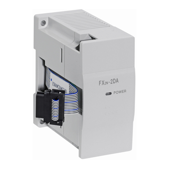
2. EXTERNAL DIMENSIONS AND PARTS
DIN rail
mounting
slot
35mm(1.38)
Mass (Weight):0.2kg (0.44lbs) Accessories: Exchange number label
3. WIRING
P L C
E xten sion
cable
Connect a 0.1 to 0.47 µF 25V DC capacitor with the position of *1 when there is voltage
*1
ripple in the voltage output or there will be a lot of noise.
*2 For voltage output please short circuit IOUT and COM as shown in the diagram.
-2DA special function block and should be read and understood before
2N
, FX
0N
Extension
cable
Mounting
holes
2holes4.5
(0.18)dia
9(0.35)
4(0.16)
87(3.43)
+15V
D C /D C
A G
converter
-15V
F X
-2D A
2N
FX
-2DA SPECIAL FUNCTIONBLOCK
2N
USER'S GUIDE
, FX
, and the FX
1N
2N
43(1.69)
V O U T
IO U T
C O M
V O U T
IO U T
C O M
*3
*3 C hann el n um ber e nter
JY992D74901C
-2DA) is used to convert a
2N
series Programmable controllers.
2NC
Dimensions: mm (inches)
M3(0.12)
terminal screws
OFF SET/GAIN
volume
V o ltag e outp ut
Inverter
*1
etc
*2
C urrent o utput
R ec order
etc
SERIES
2N
Advertisement
Table of Contents

Related Manuals for Mitsubishi FX2N-2DA


Summary of Contents for Mitsubishi FX2N-2DA
- Page 1 -2DA SPECIAL FUNCTIONBLOCK USER’S GUIDE JY992D74901C This manual contains text, diagrams and explanations which will guide the reader in the correct installation and operation of the FX -2DA special function block and should be read and understood before attempting to install or use the unit. Fur ther information can be found in the FX SERIES PROGRAMMING MANUAL,FX SERIES HARDWARE MANUAL of each PLC.
-
Page 2: Environment Specification
4. CONNECTION WITH PROGRAMMABLE CONTROLLER 1) Up to 4 FX -2DA units can be connected to an FX series PLC, up to 5 for FX up to 8 for FX up to 4 for an FX series PLC, all with powered extension units. However the following limitation exists when undermentioned special function blocks are connected. -
Page 3: Buffer Memory
5.3 Defining gain and offset Item Voltage output Current output At shipping, the unit is adjusted to a digital range of 0 to 4000 for an analog voltage output of 0 to 10V DC. When using FX -2DA by the current input or the 0 to 5V DC output, it is necessary to readjust by the offset and gain volumes. -
Page 4: Offset And Gain
7. ADJUSTMENT OF OFFSET AND GAIN 7.1 offset and gain The offset value and the gain value when the factory is shipped are adjusted for a digital value to become 0 to 4000 for the voltage output 0 to 10V. It is necessary to readjust the offset value and the gain value when -2DA is used by the current output, and FX -2DA is used by the output characteristics other than shipping the factory. -
Page 5: Program Example
8. PROGRAM EXAMPLE The following program examples (8.1 and 8.2) are formula circuits. The device numbers that have been underlined can be assigned by the user during programming. 8.1 At connection to FX series PLC X000 a)Digital data (D100) is progressed to [M0V D100 K4M100 ]... -
Page 6: Function Block
-2DA please consult the nearest Mitsubishi Electric distributor. • Under no circumstances will Mitsubishi Electric be liable or responsible for any consequential damage that may arise as a result of the installation or use of this equipment. • All examples and diagrams shown in this manual are intended only as an aid to understanding the text, not to guarantee operation. - Page 7 5.3 Defining gain and offset 4. CONNECTION WITH PROGRAMMABLE CONTROLLER Item Voltage output Current output 1) Up to 4 FX -2DA units can be connected to an FX series PLC, up to 5 for FX up to 8 for FX At shipping, the unit is adjusted to a digital range of 0 to 4000 for an analog up to 4 for an FX series PLC, all with powered extension units.
- Page 8 • Under no circumstances will Mitsubishi Electric be liable or responsible for any consequential 4000 is used with the analogue range of 4 to 20mA, a digital value of 0 is equal to an analog output of K 17 H0002 d)The high rank 4 bit data is written.
Need help?
Do you have a question about the FX2N-2DA and is the answer not in the manual?
Questions and answers