Table of Contents
Advertisement
Quick Links
Installation Guide
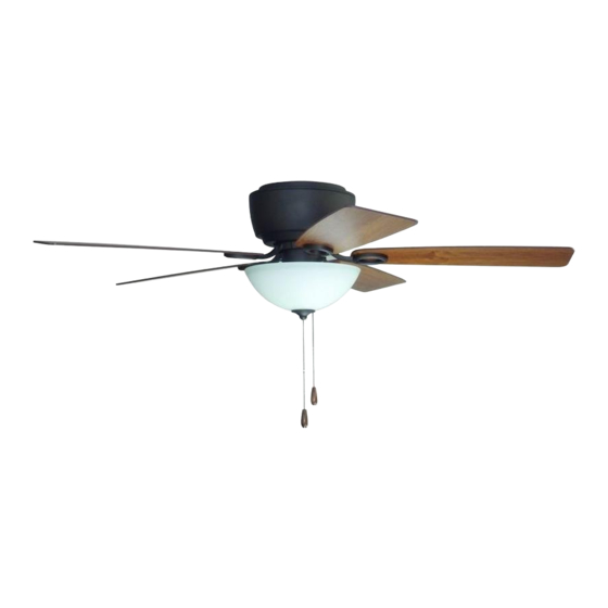
For Model:
RG52BNK5L
RG52EB5L
4009654
net weight of fan: 19 lb (8.62 kg)
READ THESE INSTRUCTIONS AND
SAVE THEM FOR FUTURE USE
Table of Contents:
Safety Tips. pg. 1
Unpacking Your Fan. pg. 2
Parts Inventory. pg. 2
Installation Preparation. pg. 3
Wiring. pg. 4
Fan Assembly. pg. 5
Motor Housing Assembly. pg. 5
Blade Assembly. pg. 6
Testing Your Fan. pg. 8
Troubleshooting. pg. 9
Parts Replacement. pg. 9
Warranty. pg. 9
PRINTED IN CHINA
Advertisement
Table of Contents

Related Manuals for Litex RG52BNK5L


Summary of Contents for Litex RG52BNK5L
-
Page 1: Table Of Contents
READ THESE INSTRUCTIONS AND SAVE THEM FOR FUTURE USE Installation Guide For Model: RG52BNK5L RG52EB5L Table of Contents: Safety Tips. pg. 1 Unpacking Your Fan. pg. 2 Parts Inventory. pg. 2 Installation Preparation. pg. 3 Hanging Bracket Installation. pgs. 3 - 4 Wiring. -
Page 2: Safety Tips
SAFETY TIPS. WARNING: To reduce the risk of electrical shock, turn off the electricity to the fan at the main fuse box or circuit panel before you begin the fan installation or before servicing the fan or installing accessories. READ ALL INSTRUCTIONS AND SAFETY INFORMATION CAREFULLY BEFORE INSTALLING YOUR FAN AND SAVE THESE INSTRUCTIONS. -
Page 3: Unpacking Your Fan
1. Unpacking Your Fan. Carefully open the packaging. Remove items from Styrofoam inserts. Remove motor housing and place on carpet or Styrofoam to avoid damage to finish. Do not discard fan carton or Styrofoam inserts should this fan need to be returned for repairs. -
Page 4: Installation Preparation
3. Installation Preparation. blade edge To prevent personal injury and damage, ensure inches that the hanging location allows the blades a 7 feet (76cm) clearance of 7ft. (2.13m) from the floor and 30in. (2.13m) (76cm) from any wall or obstruction. 12ft. -
Page 5: Wiring
4. Hanging Bracket Installation. (cont.) Install hanging bracket to outlet box using original screws, spring washers and flat washers provided with new or original outlet box.* Pull electrical wiring from outlet box through center hole in the hanging bracket. hanging bracket *Note: It is very important that you use the proper hardware when installing the hanging bracket as... -
Page 6: Fan Assembly
6. Fan Assembly. Remove motor assembly from j-hook on hanging hanging bracket. Lift motor assembly to bracket hanging bracket and carefully push j-hook wiring and wire connectors into outlet box. Align holes in top of motor assembly with bolts in hanging bracket and push up so that bolts come through holes. -
Page 7: Blade Assembly
8. Blade Assembly. WARNING: To reduce the risk of serious bodily injury, DO NOT use power tools to assemble the blades. If overtightened, blades may crack and break. motor Locate 15 blade attachment screws/washers in housing one of the hardware packs. Hold blade arm up to blade and align holes. - Page 8 9. Light Kit Assembly (Optional). (cont.) To attach light kit fitter to motor assembly, motor housing align holes in switch housing cap with holes reverse switch in switch housing and re-insert 3 screws previously removed. (Note: Make sure to align gap on edge of switch housing cap with reverse switch on switch housing for a correct fit.) Secure all screws with a Phillips...
-
Page 9: Testing Your Fan
9. Light Kit Assembly (Optional). (cont). Locate cap in one of the hardware packs motor housing switch and place cap firmly into hole in middle housing of switch housing cap. Align holes in switch housing cap with holes in switch housing. Secure switch housing cap with 3 screws and star washers that were removed at the beginning of Section 9, page 6. -
Page 10: Troubleshooting
Service at 1-800-527-1292 to arrange for return of fan. 2. Verify that reverse switch is set completely in Return fan, shipping prepaid, to Litex Industries, Ltd. We will either direction. repair or ship you a replacement fan, and we will pay the 3.
Need help?
Do you have a question about the RG52BNK5L and is the answer not in the manual?
Questions and answers