
Related Manuals for Supermicro SUPERSERVER 2028TR-HTR


Summary of Contents for Supermicro SUPERSERVER 2028TR-HTR
- Page 1 UPER ERVER ® 2028TR-HTR 2028TR-HTFR 2028TR-H72R 2028TR-H72FR USER’S MANUAL 1.0b...
- Page 2 This product, including software and documentation, is the property of Supermicro and/or its licensors, and is supplied only under a license. Any use or reproduction of this product is not allowed, except as expressly permitted by the terms of said license.
-
Page 3: About This Manual
It provides information for the installation and use of the SuperServer 2028TR-HTR/HTFR/H72R/H72FR. Installation and maintainance should be performed by experienced technicians only. The SuperServer 2028TR-HTR/HTFR/H72R/H72FR is a high-end server based on the SC217HQ-R1K68BP 2U rackmount chassis and the dual processor X10DRT-H/HIBF serverboard. - Page 4 SUPERSERVER 2028TR-HTR/HTFR/H72R/H72FR User's Manual Chapter 6: Advanced Chassis Setup Refer to Chapter 6 for detailed information on the SC217HQ-R1K68BP server chassis. You should follow the procedures given in this chapter when installing, removing or reconfiguring SATA or peripheral drives and when replacing system power supply units and cooling fans.
- Page 5 Preface Notes...
-
Page 6: Table Of Contents
SUPERSERVER 2028TR-HTR/HTFR/H72R/H72FR User's Manual Table of Contents Chapter 1 Introduction Overview ......................1-1 Serverboard Features ..................1-2 Processor ......................1-2 Memory ......................1-2 PCI Expansion Slots ..................1-2 Onboard Controllers/Ports ................1-2 Server Chassis Features ................1-4 System Power ....................1-4 Front Control Panel .................. - Page 7 Table of Contents Installing The Inner Rails on the Chassis ............2-6 Installing the Outer Rails on the Rack ............2-7 Standard Chassis Installation ................. 2-8 Chapter 3 System Interface Overview ......................3-1 Control Panel Button ..................3-2 Power ......................3-2 UID ........................
- Page 8 SUPERSERVER 2028TR-HTR/HTFR/H72R/H72FR User's Manual Serverboard Details ..................5-12 X10DRT-H/HIBF Quick Reference ..............5-12 Connector Definitions ..................5-14 Jumper Settings .................... 5-17 Explanation of Jumpers ................5-17 5-10 Onboard Indicators ..................5-20 5-11 PCI-Express and SATA Connections ............5-22 5-12 Installing Software ..................5-23 SuperDoctor®...
- Page 9 Table of Contents Security Settings ................... 7-34 Boot Settings ....................7-35 Save & Exit ....................7-37 Appendix A BIOS Error Beep Codes Appendix B System Specifications...
- Page 10 SUPERSERVER 2028TR-HTR/HTFR/H72R/H72FR User's Manual Notes...
-
Page 11: Chapter 1 Introduction
Chapter 1 Introduction Overview The SuperServer 2028TR-HTR/HTFR/H72R/H72FR is a high-end server comprised of two main subsystems: the SC217HQ-R1K68BP 2U server chassis and four X10DRT-H/HIBF dual processor serverboards. Please refer to our web site for information on operating systems that have been certified for use with the system (www.supermicro.com). -
Page 12: Serverboard Features
SUPERSERVER 2028TR-HTR/HTFR/H72R/H72FR User's Manual Serverboard Features At the heart of the SuperServer 2028TR-HTR/HTFR/H72R/H72FR lies four X10DRT-H/HIBF dual processor serverboards based upon the Intel ® C612 chipset. Below are the main features of the X10DRT-H/HIBF. Note that the features on each board are quadrupled for the server, which includes four nodes. -
Page 13: System Block Diagram
Chapter 1: Introduction Figure 1-1. Intel C612 Chipset: System Block Diagram Note: This is a general block diagram and may not exactly represent the features on your serverboard. See the previous pages for the actual specifications of your serverboard. VR12.5 VR12.5 #2-4 #1-4... -
Page 14: Server Chassis Features
SUPERSERVER 2028TR-HTR/HTFR/H72R/H72FR User's Manual Server Chassis Features The following is a general outline of the main features of the SC217HQ server chassis. System Power Each SC217HQ chassis model includes a high-efficiency 80-plus Titanium certified power supply, rated at 1600 watts plus one redundant backup power supply. In the unlikely event your power supply fails, replacement is simple and can be accomplished without tools. -
Page 15: Contacting Supermicro
Super Micro Computer, Inc. 980 Rock Ave. San Jose, CA 95131 U.S.A. Tel: +1 (408) 503-8000 Fax: +1 (408) 503-8008 Email: marketing@supermicro.com (General Information) support@supermicro.com (Technical Support) Website: www.supermicro.com Europe Address: Super Micro Computer B.V. Het Sterrenbeeld 28, 5215 ML... -
Page 16: Twin 2 : System Notes
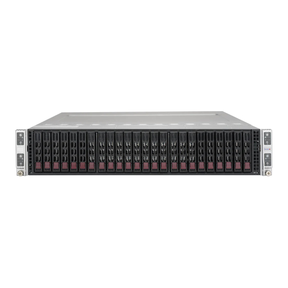
Hard Drive Backplane/Drives The SuperServer 2028TR-HTR/HTFR/H72R/H72FR supports the use of 24 hard drives (SATA). A single backplane works to apply system-based control for power and fan speed functions and logically connects a set of six hard drives to each serverboard/node. -
Page 17: Chapter 2 Server Installation
Read the Rack and Server Precautions in the next section. Preparing for Setup The box the SuperServer 2028TR-HTR/HTFR/H72R/H72FR was shipped in should include two sets of rail assemblies, two rail mounting brackets and the mounting screws you will need to install the system into the rack. Follow the steps in the order given to complete the installation process in a minimum amount of time. -
Page 18: Choosing A Setup Location
SUPERSERVER 2028TR-HTR/HTFR/H72R/H72FR User's Manual Choosing a Setup Location • Leave enough clearance in front of the rack to enable you to open the front door completely (~25 inches) and approximately 30 inches of clearance in the back of the rack to allow for sufficient airflow and ease in servicing. -
Page 19: Rack Mounting Considerations
Chapter 2: Server Installation Rack Mounting Considerations Ambient Operating Temperature If installed in a closed or multi-unit rack assembly, the ambient operating temperature of the rack environment may be greater than the ambient temperature of the room. Therefore, consideration should be given to installing the equipment in an environment compatible with the manufacturer’s maximum rated ambient temperature (Tmra). -
Page 20: Installing The System Into A Rack
SUPERSERVER 2028TR-HTR/HTFR/H72R/H72FR User's Manual Installing the System into a Rack This section provides information on installing the 2028TR-HTR/HTFR/H72R/H72FR into a rack unit with the rails provided. There are a variety of rack units on the market, which may mean that the assembly procedure will differ slightly from the instructions provided. -
Page 21: Locking Tabs
Chapter 2: Server Installation Locking Tabs Each inner rail has a locking tab. This tab locks the chassis into place when installed and pushed fully into the rack. These tabs also lock the chassis in place when fully extended from the rack. This prevents the server from coming completely out of the rack when when the chassis is pulled out for servicing. -
Page 22: Installing The Inner Rails On The Chassis
SUPERSERVER 2028TR-HTR/HTFR/H72R/H72FR User's Manual Installing The Inner Rails on the Chassis To install the inner rails, use the procedure below. Installing the Inner Rails (Figures 2-3 and 2-4) 1. Confirm that the left and right inner rails have been correctly identified. -
Page 23: Installing The Outer Rails On The Rack
Chapter 2: Server Installation Installing the Outer Rails on the Rack Use the procedure below to install the outer rails onto the rack. Installing the Outer Rails (Figure 2-5) 1. Press upward on the locking tab at the rear end of the middle rail. 2. -
Page 24: Standard Chassis Installation
SUPERSERVER 2028TR-HTR/HTFR/H72R/H72FR User's Manual Standard Chassis Installation Installing the Chassis into a Rack (Figure 2-6) 1. Confirm that the inner rails are properly installed on the chassis. 2. Confirm that the outer rails are correctly installed on the rack. 3. Pull the middle rail out from the front of the outer rail and make sure that the ball-bearing shuttle is at the front locking position of the middle rail. -
Page 25: Chapter 3 System Interface
Chapter 3: System Interface Chapter 3 System Interface Overview There are several LEDs on the control panel and on the drive carriers to keep you constantly informed of the overall status of the system. SC217HQ models include four front panels on the handles of the chassis which control each of the systems. This chapter explains the meanings of all LED indicators and the appropriate response you may need to take. -
Page 26: Control Panel Button
SUPERSERVER 2028TR-HTR/HTFR/H72R/H72FR User's Manual Control Panel Button Power The main power button on each of the four control panels is used to apply or remove power from the power supply to each of the four systems in the chassis. Turning power to the system off with this button removes the main power, but keeps standby power supplied to the system. -
Page 27: Nic
Chapter 3: System Interface • A flashing red light which flashes in four second interfals indicates a power failure. When notified of an alert, check the routing of the cables and make sure all fans are present and operating normally. You should also check to make sure that the chassis covers and air shrouds are installed. - Page 28 SUPERSERVER 2028TR-HTR/HTFR/H72R/H72FR User's Manual Notes...
-
Page 29: About Standardized Warning Statements
Only certified technicians should attempt to install or configure components. Read this appendix in its entirety before installing or configuring components in the Supermicro chassis. These warnings may also be found on our web site at http://www.supermicro.com/ about/policies/safety_information.cfm. Warning Definition Warning! This warning symbol means danger. - Page 30 SUPERSERVER 2028TR-HTR/HTFR/H72R/H72FR User's Manual Warnung WICHTIGE SICHERHEITSHINWEISE Dieses Warnsymbol bedeutet Gefahr. Sie befinden sich in einer Situation, die zu Verletzungen führen kann. Machen Sie sich vor der Arbeit mit Geräten mit den Gefahren elektrischer Schaltungen und den üblichen Verfahren zur Vorbeugung vor Unfällen vertraut.
- Page 31 Warning Statements for AC Systems جسذٌة اصابة ًتتسبب ف حالة ٌوكي أى ًاًك ف خطز ًٌٌع هذا الزهز !تحذٌز الذوائز بالوخاطز الٌاجوة عي ي على علن ، ك هعذات تعول على أي قبل أى الكهزبائٍة حىادث أي وقىع وٌع ل الىقائٍة...
-
Page 32: Installation Instructions
SUPERSERVER 2028TR-HTR/HTFR/H72R/H72FR User's Manual Installation Instructions Warning! Read the installation instructions before connecting the system to the power source. 設置手順書 システムを電源に接続する前に、 設置手順書をお読み下さい。 警告 将此系统连接电源前,请先阅读安装说明。 警告 將系統與電源連接前,請先閱讀安裝說明。 Warnung Vor dem Anschließen des Systems an die Stromquelle die Installationsanweisungen lesen. ¡Advertencia! Lea las instrucciones de instalación antes de conectar el sistema a la red de alimentación. -
Page 33: Circuit Breaker
Chapter 4: Warning Statements for AC Systems Circuit Breaker Warning! This product relies on the building's installation for short-circuit (overcurrent) protection. Ensure that the protective device is rated not greater than: 250 V, 20 A. サーキッ ト ・ ブレーカー この製品は、 短絡 (過電流) 保護装置がある建物での設置を前提としています。 保護装置の定格が250 V、... -
Page 34: Power Disconnection Warning
SUPERSERVER 2028TR-HTR/HTFR/H72R/H72FR User's Manual في التي تم تثبيتها مه الدوائرالقصيرة الحمايت معداث يعتمد على هذا المنتج المبنى أكثر من ليس وقائي ال الجهاز تقييم أن تأكد من 20A, 250V 경고! 이 제품은 전원의 단락(과전류)방지에 대해서 전적으로 건물의 관련 설비에 의존합니다. 보호장치의 정격이 반드시 250V(볼트), 20A(암페어)를 초과하지... - Page 35 Chapter 4: Warning Statements for AC Systems Warnung Das System muss von allen Quellen der Energie und vom Netzanschlusskabel getrennt sein, das von den Spg.Versorgungsteilmodulen entfernt wird, bevor es auf den Chassisinnenraum zurückgreift, um Systemsbestandteile anzubringen oder zu entfernen. ¡Advertencia! El sistema debe ser disconnected de todas las fuentes de energía y del cable eléctrico quitado de los módulos de fuente de alimentación antes de tener acceso el interior del chasis para instalar o para quitar componentes de sistema.
-
Page 36: Equipment Installation
SUPERSERVER 2028TR-HTR/HTFR/H72R/H72FR User's Manual Equipment Installation Warning! Only trained and qualified personnel should be allowed to install, replace, or service this equipment. 機器の設置 トレーニングを受け認定された人だけがこの装置の設置、 交換、 またはサービスを許可 されています。 警告 只有经过培训且具有资格的人员才能进行此设备的安装、更换和维修。 警告 只有經過受訓且具資格人員才可安裝、更換與維修此設備。 Warnung Das Installieren, Ersetzen oder Bedienen dieser Ausrüstung sollte nur geschultem, qualifiziertem Personal gestattet werden. -
Page 37: Restricted Area
Chapter 4: Warning Statements for AC Systems Waarschuwing Deze apparatuur mag alleen worden geïnstalleerd, vervangen of hersteld door geschoold en gekwalificeerd personeel. Restricted Area Warning! This unit is intended for installation in restricted access areas. A restricted access area can be accessed only through the use of a special tool, lock and key, or other means of security. -
Page 38: Battery Handling
SUPERSERVER 2028TR-HTR/HTFR/H72R/H72FR User's Manual אזור עם גישה מוגבלת !אזהרה יש להתקין את היחידה באזורים שיש בהם הגבלת גישה. הגישה ניתנת בעזרת .)'כלי אבטחה בלבד (מפתח, מנעול וכד محظورة مناطق ٍنتركُبها ف هذه انىحذة تخصيص تم ،أداة خاصت من خالل استخذاو... - Page 39 Chapter 4: Warning Statements for AC Systems Warnung Bei Einsetzen einer falschen Batterie besteht Explosionsgefahr. Ersetzen Sie die Batterie nur durch den gleichen oder vom Hersteller empfohlenen Batterietyp. Entsorgen Sie die benutzten Batterien nach den Anweisungen des Herstellers. Attention Danger d'explosion si la pile n'est pas remplacée correctement. Ne la remplacer que par une pile de type semblable ou équivalent, recommandée par le fabricant.
-
Page 40: Redundant Power Supplies
SUPERSERVER 2028TR-HTR/HTFR/H72R/H72FR User's Manual Redundant Power Supplies Warning! This unit might have more than one power supply connection. All connections must be removed to de-energize the unit. 冗長電源装置 このユニッ トは複数の電源装置が接続されている場合があります。 ユニッ トの電源を切るためには、 すべての接続を取り外さなければなりません。 警告 此部件连接的电源可能不止一个,必须将所有电源断开才能停止给该部件供电。 警告 此裝置連接的電源可能不只一個,必須切斷所有電源才能停止對該裝置的供電。 Warnung Dieses Gerät kann mehr als eine Stromzufuhr haben. Um sicherzustellen, dass der Einheit kein trom zugeführt wird, müssen alle Verbindungen entfernt werden. -
Page 41: Backplane Voltage
Chapter 4: Warning Statements for AC Systems امداد الطاقة بوحدات عدة اتصاالت جهاز ال يكون لهذا قد الكهرباء عن وحدة ال لعسل كافة االتصاالت يجب إزالة 경고! 이 장치에는 한 개 이상의 전원 공급 단자가 연결되어 있을 수 있습니다. 이 장치에 전원을... -
Page 42: Comply With Local And National Electrical Codes
SUPERSERVER 2028TR-HTR/HTFR/H72R/H72FR User's Manual Attention Lorsque le système est en fonctionnement, des tensions électriques circulent sur le fond de panier. Prendre des précautions lors de la maintenance. מתח בפנל האחורי !הרה אז קיימת סכנת מתח בפנל האחורי בזמן תפעול המערכת. יש להיזהר במהלך... -
Page 43: Product Disposal
Chapter 4: Warning Statements for AC Systems ¡Advertencia! La instalacion del equipo debe cumplir con las normas de electricidad locales y nacionales.Attention L'équipement doit être installé conformément aux normes électriques nationales et locales. תיאום חוקי החשמל הארצי !אזהרה הציוד חייבת להיות תואמת לחוקי החשמל המקומיים והארציים התקנת... -
Page 44: Hot Swap Fan Warning
SUPERSERVER 2028TR-HTR/HTFR/H72R/H72FR User's Manual Warnung Die Entsorgung dieses Produkts sollte gemäß allen Bestimmungen und Gesetzen des Landes erfolgen. ¡Advertencia! Al deshacerse por completo de este producto debe seguir todas las leyes y reglamentos nacionales. Attention La mise au rebut ou le recyclage de ce produit sont généralement soumis à des lois et/ou directives de respect de l'environnement. - Page 45 Chapter 4: Warning Statements for AC Systems 当您从机架移除风扇装置,风扇可能仍在转动。小心不要将手指、螺丝起子和其他 物品太靠近风扇 警告 當您從機架移除風扇裝置,風扇可能仍在轉動。小心不要將手指、螺絲起子和其他 物品太靠近風扇。 Warnung Die Lüfter drehen sich u. U. noch, wenn die Lüfterbaugruppe aus dem Chassis genommen wird. Halten Sie Finger, Schraubendreher und andere Gegenstände von den Öffnungen des Lüftergehäuses entfernt. ¡Advertencia! Los ventiladores podran dar vuelta cuando usted quite ell montaje del ventilador del chasis.
-
Page 46: Power Cable And Ac Adapter
Electrical Appliance and Material Safety Law prohibits the use of UL or CSA -certified cables (that have UL/CSA shown on the code) for any other electrical devices than products designated by Supermicro only. 電源コードとACアダプター 製品を設置する場合、 提供または指定された接続ケーブル、 電源コードとACアダプター... - Page 47 Appareils électroménagers et de loi sur la sécurité Matériel interdit l'utilisation de UL ou CSA câbles certifiés qui ont UL ou CSA indiqué sur le code pour tous les autres appareils électriques que les produits désignés par Supermicro seulement.
- Page 48 Elektrisch apparaat en veiligheidsinformatiebladen wet verbiedt het gebruik van UL of CSA gecertificeerde kabels die UL of CSA die op de code voor andere elektrische apparaten dan de producten die door Supermicro alleen. 4-20...
-
Page 49: Chapter 5 Advanced Serverboard Setup
Chapter 5: Advanced Serverboard Setup Chapter 5 Advanced Serverboard Setup This chapter covers the steps required to connect the data and power cables and install add-on cards. All serverboard jumpers and connections are also described. A layout and quick reference chart are included in this chapter for your reference. Remember to completely close the chassis when you have finished working with the serverboard to better cool and protect the system. -
Page 50: Connecting Cables
SUPERSERVER 2028TR-HTR/HTFR/H72R/H72FR User's Manual Connecting Cables Now that the processors are installed, the next step is to connect the cables to the serverboard. Connecting Data Cables The cables used to transfer data from the peripheral devices have been carefully routed in preconfigured systems to prevent them from blocking the flow of cooling air that moves through the system from front to back. -
Page 51: Rear I/O Ports
Chapter 5: Advanced Serverboard Setup Rear I/O Ports See Figure 5-1 below for the locations of the various rear I/O ports and the UID switch. Figure 5-1. Rear I/O Ports Rear I/O Ports Dedicated IPMI LAN Back Panel USB 3.0 Port 1 Back Panel USB 3.0 Port 0 Gigabit LAN 1 Gigabit LAN 2... -
Page 52: Processor And Heatsink Installation
• Install the processor into the CPU socket before installing the heatsink. • Refer to the Supermicro web site for updates on CPU support. Installing a CPU 1. There are two levers on the LGA 2011 socket. First press and release the load lever labeled "Open 1st". - Page 53 Chapter 5: Advanced Serverboard Setup 3. With the second lever fully Open the load plate. retracted, gently push down on the "Open 1st" lever to loosen the load plate. Lift the load plate with your fingers to open it completely. IMPORTANT! 4.
- Page 54 SUPERSERVER 2028TR-HTR/HTFR/H72R/H72FR User's Manual Gently close the load plate. 7. With the "Close 1st" lever fully retracted, gently close the load plate. Push down and lock the lever labeled "Close 1st". 8. Make sure the locking mechanism on the "Close 1st" lever catches the lip of the load plate.
-
Page 55: Installing A Passive Cpu Heatsink
Chapter 5: Advanced Serverboard Setup Installing a Passive CPU Heatsink 1. Do not apply any thermal grease to the heatsink or the CPU die - the required amount has already been applied. 2. Place the heatsink on top of the CPU so that the four mounting holes are aligned with those on the serverboard and the heatsink bracket underneath. -
Page 56: Removing The Heatsink
SUPERSERVER 2028TR-HTR/HTFR/H72R/H72FR User's Manual Removing the Heatsink Caution: We DO NOT recommend that the CPU or the heatsink be removed. However, if you do need to uninstall the heatsink, please follow the instructions below to prevent damage to the CPU or the CPU socket. -
Page 57: Installing Memory
For the memory modules to work properly, please install DIMM modules in pairs (w/even number of DIMMs installed). All channels in a system will run at the fastest common frequency. Check the Supermicro website (www.supermicro.com) for the latest memory support information. Figure 5-4. DIMM Installation... -
Page 58: Dimm Slots
SUPERSERVER 2028TR-HTR/HTFR/H72R/H72FR User's Manual Processor & Memory Module Population Configuration For the memory to work properly, follow the tables below when populating the DIMM slots. Processors and their Corresponding Memory Modules CPU# Corresponding DIMM Modules CPU 1 DIMMA1 DIMMB1 DIMMC1... -
Page 59: Adding Pci Expansion Cards
Chapter 5: Advanced Serverboard Setup Adding PCI Expansion Cards The 2028TR-HTR/HTFR/H72R/H72FR includes one preinstalled riser card per node, designed specifically for use in the SC217HQ-R1K68BP 2U rackmount chassis. This riser card (RSC-R2UTP-E16R) supports one standard size PCI Express x16 card to fit inside the chassis for each node. Installing an Expansion Card 1. -
Page 60: Serverboard Details
SUPERSERVER 2028TR-HTR/HTFR/H72R/H72FR User's Manual Serverboard Details Figure 5-5. X10DRT-H/HIBF Serverboard Layout (not drawn to scale) COM1 JCOM1 JVGA JUIDB1 JIB1 LAN2 LAN1 QSFP LEDBMC JUSBRJ45 JSTBY1 JPB1:BMC 1-2:ENABLE 2-3:DISABLE JBT1: CMOS CLEAR JSD2 CPU1 CLOSE 1st OPEN 1st CPU2 CLOSE 1st... - Page 61 Chapter 5: Advanced Serverboard Setup Jumper Description Default Setting JVRM1/JVRM2 C Bus for VRM Pins 1-2 (BMC: Normal) JBT1 Clear CMOS See Section 5-9 JPB1 BMC Enable/Disable Pins 1-2 (Enabled) JPG1 VGA Enable/Disable Pins 1-2 (Enabled) JPL1 LAN Enable/Disable Pins 1-2 (Enabled) JI2C1/JI2C2 SMB to PCI Slots Pins 1-2 (Enabled)
-
Page 62: Connector Definitions
Front Panel Control connections for the X10DRT series serverboard. Insert an Add- On card into this connector to use the functions indicated above. This connector is designed specifically for a Supermicro-proprietary add-on card. Refer to the layout below for the location of JF1. - Page 63 Chapter 5: Advanced Serverboard Setup QSFP Connector The FDR 56 GT/s (4-channel) Small Form-factor Pluggable (QSFP) connector used as an InfiniBand (IB) port is located on the backpanel on the X10DRT-HIBF. The IB connection is primarily used for High-performance computing. VGA Port A VGA (video) port is provided on the I/O backplane.
- Page 64 SUPERSERVER 2028TR-HTR/HTFR/H72R/H72FR User's Manual Fan Headers This serverboard has one system Fan Header fan header (Fan 3). This 4-pin fans Pin Definitions header is backward compatible with Pin# Definition traditional 3-pin fans. However, fan Ground speed control is available for 4-pin fans +12V only.
-
Page 65: Jumper Settings
Chapter 5: Advanced Serverboard Setup Jumper Settings Connector Pins Explanation of Jumpers To modify the operation of the serverboard, Jumper jumpers can be used to choose between optional settings. Jumpers create shorts between two pins to change the function Setting of the connector. - Page 66 SUPERSERVER 2028TR-HTR/HTFR/H72R/H72FR User's Manual Watch Dog Enable/Disable Watch Dog (JWD1) is a system monitor Watch Dog that can reboot the system when a Jumper Settings software application hangs. Close pins Jumper Setting Definition 1-2 to reset the system if an application...
- Page 67 Chapter 5: Advanced Serverboard Setup InfiniBand Enable InfiniBand Enable Jumper Settings Jumper JIB1 enables the onboard Jumper Setting Definition InfiniBand functions on the X10DRT- Pins 1-2 Enabled HIBF. See the table on the right for Pins 2-3 Disabled jumper settings. C Bus for VRM C Bus for VRM Jumper Settings...
-
Page 68: 5-10 Onboard Indicators
SUPERSERVER 2028TR-HTR/HTFR/H72R/H72FR User's Manual 5-10 Onboard Indicators LAN Port LEDs The LAN ports are located on the rear I/O LAN Port LED (Connection Speed Indicator) panel. On each Gb LAN port, one LED LED Color Definition blinks to indicate activity while the other... - Page 69 Chapter 5: Advanced Serverboard Setup InfiniBand Link LED (Green) Status Color Status Definition InfiniBand LED Indicators Green Solid InfiniBand Connected The X10DRT-HIBF has two InfiniBand No Connection LED indicators. The green LED is the InfiniBand Activity LED (Yellow) InfiniBand Link LED and the yellow LED Status indicates activity.
-
Page 70: 5-11 Pci-Express And Sata Connections
SUPERSERVER 2028TR-HTR/HTFR/H72R/H72FR User's Manual 5-11 PCI-Express and SATA Connections I-SATA 0-1/CPU1_PCI-Express 3.0 x8 (in x4) Slot (SXB1) A CPU1_PCI-Express 3.0 x8 slot and I-SATA 0-5 connections are located on the serverboard. S-SATA 0-1/CPU2_PCI-Express 3.0 x8 (in x4) Slot (SXB2) A CPU2_PCI-Express 3.0 x16 slot and S-SATA 0-2 connections are located on the serverboard. -
Page 71: 5-12 Installing Software
Chapter 5: Advanced Serverboard Setup 5-12 Installing Software The Supermicro ftp site contains drivers and utilities for your system at ftp://ftp. supermicro.com. Some of these must be installed, such as the chipset driver. After accessing the ftp site, go into the CDR_Images directory and locate the ISO file for your serverboard. -
Page 72: Superdoctor® 5
SUPERSERVER 2028TR-HTR/HTFR/H72R/H72FR User's Manual SuperDoctor® 5 The Supermicro SuperDoctor 5 is a program that functions in a command-line or web-based interface in Windows and Linux operating systems. The program monitors system health information such as CPU temperature, system voltages, system power consumption, fan speed, and provides alerts via email or Simple Network Management Protocol (SNMP). -
Page 73: 5-13 Onboard Battery
Chapter 5: Advanced Serverboard Setup 5-13 Onboard Battery Please handle used batteries carefully. Do not damage the battery in any way; a damaged battery may release hazardous materials into the environment. Do not discard a used battery in the garbage or a public landfill. Please comply with the regulations set up by your local hazardous waste management agency to dispose of your used battery properly. - Page 74 SUPERSERVER 2028TR-HTR/HTFR/H72R/H72FR User's Manual Notes 5-26...
-
Page 75: Chapter 6 Advanced Chassis Setup
Chapter 6: Advanced Chassis Setup Chapter 6 Advanced Chassis Setup This chapter covers the steps required to install components and perform maintenance on the SC217HQ-R1K68BP chassis. For component installation, follow the steps in the order given to eliminate the most common problems encountered. If some steps are unnecessary, skip ahead to the step that follows. -
Page 76: Front And Rear Views
SUPERSERVER 2028TR-HTR/HTFR/H72R/H72FR User's Manual Front and Rear Views There is a control panel located on the front edge of the chassis for each computing node. The control panel offers a power switch and status LEDs as described in Chapter 3. -
Page 77: Chassis Cover
Chapter 6: Advanced Chassis Setup Chassis Cover Before operating the system for the first time, it is important to remove the protective film covering the top of the chassis, to allow for proper ventilation and cooling. Removing the Chassis Cover and Protective Film This procedure is also described in Chapter 2. -
Page 78: Air Shrouds
SUPERSERVER 2028TR-HTR/HTFR/H72R/H72FR User's Manual Air Shrouds Air shrouds concentrate airflow to maximize fan efficiency. The SC217 chassis requires air shrouds for each serverboard node. Air shrouds vary depending upon the serverboard used. See the illustrations below. Installing an Air Shroud 1. -
Page 79: System Fans
Chapter 6: Advanced Chassis Setup System Fans Four fans circulate air through the chassis to help control the chassis internal temperature. The system fans are easy to change. If one of the node drawers is removed, the two associated fans will stop. Changing a System Fan 1. -
Page 80: Checking The Airflow
SUPERSERVER 2028TR-HTR/HTFR/H72R/H72FR User's Manual Figure 6-6. System Fan Placement 6. Put the fan housing back into the chassis and reconnect the cables. 7. Confirm that the fan is working properly before replacing the chassis cover. Checking the Airflow Checking Airflow •... -
Page 81: Replacing The Backplane
Chapter 6: Advanced Chassis Setup Replacing the Backplane The SC217 chassis backplane is located behind the hard drives and in front of the system fans. In the unlikely event of a backplane failure, follow the instructions below. Removing the Backplane Removing the Backplane from the Chassis 1. - Page 82 SUPERSERVER 2028TR-HTR/HTFR/H72R/H72FR User's Manual 6. Loosen the three screws in the spring bar, located on the floor of the chassis, indicated by the arrows (see Figure 6-7). Figure 6-8. Loosening the Spring Bar Screws in the Floor of the Chassis 7.
-
Page 83: Installing The Backplane
Chapter 6: Advanced Chassis Setup Installing the Backplane Installing the Backplane into the Chassis 1. Ensure that all of the hard drive carriers have been removed from the bays in the front of the chassis and that the spring bar has been loosened as directed in the previous section. -
Page 84: Installing The Serverboard
SUPERSERVER 2028TR-HTR/HTFR/H72R/H72FR User's Manual Installing the Serverboard I/O Shield The I/O shield holds the serverboard ports in place. The I/O shield does not require installation. Figure 6-11. I/O Shield Placement I/O Shields Permanent and Optional Standoffs Standoffs prevent short circuits by creating space between the serverboard and the chassis surface. - Page 85 Chapter 6: Advanced Chassis Setup 4. Lay the serverboard in the node drawer aligning the standoffs with the serverboard. 5. Secure the serverboard to the node drawer using the rounded, Phillips head screws included for this purpose. Do not apply more than 8 inch-lbs. of torque 6.
-
Page 86: Installing The Adapter Card
SUPERSERVER 2028TR-HTR/HTFR/H72R/H72FR User's Manual Installing the Adapter Card Each node drawer comes equipped with an adapter card that connects the serverboard to the backplane. See the table below for the adapter card that ships with each system. Installing the Adapter Card 1. -
Page 87: Adding Expansion Cards
Chapter 6: Advanced Chassis Setup Adding Expansion Cards The SC217 chassis includes I/O slots for add-on cards and expansion cards. Each side supports one low-profile/half length add-on card for a total of four per chassis, or one per node. A riser card is necessary to mount the expansion cards. The riser card is preinstalled in each node. - Page 88 SUPERSERVER 2028TR-HTR/HTFR/H72R/H72FR User's Manual Installing Expansion Cards 1. Disconnect the chassis from any power source, lay the chassis on a flat surface, and open the chassis cover. 2. Pull out the motherboard node drawer from the chassis. 3. Pull open the expansion card PCI slot clip in the rear of the motherboard node drawer.
-
Page 89: Installing And Removing Hard Drives
Chapter 6: Advanced Chassis Setup Installing and Removing Hard Drives The SC217 chassis features 24 drive bays that are accessable for drive replacement from the front of the chassis. The drives are mounted in drive carriers to simplify their installation and removal. These carriers also help promote proper airflow for the drive bays. - Page 90 SUPERSERVER 2028TR-HTR/HTFR/H72R/H72FR User's Manual Removing Hard Drive Carriers from the Chassis 1. Press the release button on the drive carrier. This extends the drive bay handle. 2. Use the handle to pull the drive out of the chassis (Figure 6-17).
- Page 91 Chapter 6: Advanced Chassis Setup Figure 6-18. Removing a Dummy Drive from Carrier Dummy Drive Drive Carrier Installing a Drive into the Carrier 1. Install a new drive into the carrier with the printed circuit board side facing down so that the mounting holes in the drive align with those in the carrier. 2.
-
Page 92: 6-10 Power Supply
Replacement units can be ordered directly from Supermicro. (See the contact information in the Preface of this manual.) Changing the Power Supply 1. -
Page 93: Chapter 7 Bios
Chapter 7: BIOS Chapter 7 BIOS Introduction This chapter describes the AMI BIOS Setup utility for the X10DRT-H/HIBF. It also provides the instructions on how to navigate the AMI BIOS Setup utility screens. The AMI ROM BIOS is stored in a Flash EEPROM and can be easily updated. Starting BIOS Setup Utility To enter the AMI BIOS Setup utility screens, press the <Del>... -
Page 94: How To Change The Configuration Data
SUPERSERVER 2028TR-HTR/HTFR/H72R/H72FR User's Manual How To Change the Configuration Data The configuration data that determines the system parameters may be changed by entering the AMI BIOS Setup utility. This Setup utility can be accessed by pressing <F2> at the appropriate time during system boot. - Page 95 This item displays the system date in Day MM/DD/YY format (e.g. Wed 10/12/2011). System Time This item displays the system time in HH:MM:SS format (e.g. 15:32:52). Supermicro X10DRT-H BIOS Version This item displays the version of the BIOS ROM used in this system.
-
Page 96: Advanced Setup Configurations
SUPERSERVER 2028TR-HTR/HTFR/H72R/H72FR User's Manual Advanced Setup Configurations Use the arrow keys to select Advanced Setup and press <Enter> to access the following submenu items. Boot Features Quiet Boot This feature selects the bootup screen display between POST messages and the OEM logo. Select Disabled to display the POST messages. Select Enabled to display the OEM logo instead of the normal POST messages. -
Page 97: Power Configuration
Chapter 7: BIOS Interrupt 19 Capture Interrupt 19 is the software interrupt that handles the boot disk function. When this item is set to Enabled, the ROM BIOS of the host adaptors will "capture" Interrupt 19 at bootup and allow the drives that are attached to these host adaptors to function as bootable disks. -
Page 98: Cpu Configuration
SUPERSERVER 2028TR-HTR/HTFR/H72R/H72FR User's Manual CPU Configuration This submenu displays the information of the CPU as detected by the BIOS. It also allows the user to configuration CPU settings. Socket 1 CPU Information/Socket 2 CPU Information This submenu displays the following information regarding the CPU installed in Socket 1 and (or) Socket 2 as detected by the BIOS. - Page 99 Chapter 7: BIOS Execute-Disable Bit Capability (Available if supported by the OS & the CPU) Select Enabled to enable the Execute-Disable Bit which will allow the processor to designate areas in the system memory where an application code can execute and where it cannot, thus preventing a worm or a virus from flooding illegal codes to overwhelm the processor or damage the system during an attack.
-
Page 100: Cpu Power Management Configuration
SUPERSERVER 2028TR-HTR/HTFR/H72R/H72FR User's Manual Intel® Virtualization Technology (Available when supported by the CPU) Select Enabled to support Intel Virtualization Technology, which will allow one platform to run multiple operating systems and applications in independent parti- tions, creating multiple "virtual" systems in one physical computer. The options are Enabled and Disabled. -
Page 101: Cpu C State Control
Chapter 7: BIOS CPU C State Control Package C-State limit This feature allows the user to set the limit on the C-State package register. The options are C0/C1 State, C2 State, C6 (Non Retention) State, and C6 (Rententioin) State. CPU C3 Report Select Enabled to allow the BIOS to report the CPU C3 State (ACPI C2) to the operating system. - Page 102 SUPERSERVER 2028TR-HTR/HTFR/H72R/H72FR User's Manual IIO1 Configuration IOU2 (II0 PCIe Port 1) This item configures the PCI-E port Bifuraction setting for a PCI-E port specified by the user. The options are x4x4, X8, and Auto. IOU0 (II0 PCIe Port 2) This item configures the PCI-E port Bifuraction setting for a PCI-E port specified by the user.
- Page 103 Chapter 7: BIOS IOU1 (II02 PCIE Port 3) Use this item to configure the PCI-E port Bifuraction setting for a PCI-E port speci- fied by the user. The options are x4x4x4x4, x4x4x8, x8x4x4, x8x8, x16, and Auto. IOAT (Intel® IO Acceleration) Configuration Enable IOAT Select Enable to enable Intel I/OAT (I/O Acceleration Technology) support, which significantly reduces CPU overhead by leveraging CPU architectural improve-...
- Page 104 SUPERSERVER 2028TR-HTR/HTFR/H72R/H72FR User's Manual QPI (Quick Path Interconnect) Configuration QPI Status The following information will display: • Number of CPU • Number of IIO • Current QPI Link Speed • Current QPI Link Frequency • QPI Global MMIO Low Base/Limit •...
-
Page 105: Memory Configuration
Chapter 7: BIOS Memory Configuration Enforce POR Select Enable to enforce POR restrictions on DDR4 frequency and voltage programming. The options are Enabled and Disabled. Memory Frequency Use this feature to set the maximum memory frequency for onboard memory modules. The options are Auto, 1333, 1400, 1600, 1800, 1867, 2000, 2133, 2200, 2400, 2600, 2667, and Reserved (Do not select Reserved). - Page 106 SUPERSERVER 2028TR-HTR/HTFR/H72R/H72FR User's Manual Memory RAS (Reliability Availability Serviceability) Configuration Use this submenu to configure the following Memory RAS settings. RAS Mode When Disable is selected, RAS is not supported. When Mirror is selected, the motherboard maintains two identical copies of all data in memory for data backup.
-
Page 107: South Bridge Configuration
Chapter 7: BIOS South Bridge Configuration The following South Bridge information will display: USB Configuration • USB Module Version • USB Devices Legacy USB Support Select Enabled to support onboard legacy USB devices. Select Auto to disable legacy support if there are no legacy USB devices present. Select Disable to have all USB devices available for EFI applications only. -
Page 108: Sata Configuration
SUPERSERVER 2028TR-HTR/HTFR/H72R/H72FR User's Manual EHCI2 Select Enabled to enable EHCI (Enhanced Host Controller Interface) support on USB 2.0 connector #2 (-at least one USB 2.0 connector should be enabled for EHCI support.) The options are Disabled and Enabled. XHCI Pre-Boot Drive Select Enabled to enable XHCI (Extensible Host Controller Interface) support on a pre-boot drive specified by the user. - Page 109 Chapter 7: BIOS Port 0 ~ Port 5 Spin Up Device On an edge detect from 0 to 1, set this item to allow the PCH to initialize the device. The options are Enabled and Disabled. Port 0 ~ Port 5 SATA Device Type Use this item to specify if the SATA port specified by the user should be con- nected to a Solid State drive or a Hard Disk Drive.
- Page 110 SUPERSERVER 2028TR-HTR/HTFR/H72R/H72FR User's Manual Serial ATA Port 0~ Port 5 This item displays the information detected on the installed SATA drives on the particular SATA port. • Model number of drive and capacity • Software Preserve Support Port 0~ Port 5 Select Enabled to enable a SATA port specified by the user.
- Page 111 Chapter 7: BIOS Support Aggressive Link Power Management When this item is set to Enabled, the SATA AHCI controller manages the power usage of the SATA link. The controller will put the link to a low power state when the I/O is inactive for an extended period of time, and the power state will return to normal when the I/O becomes active.
- Page 112 SUPERSERVER 2028TR-HTR/HTFR/H72R/H72FR User's Manual *If the item above "Configure sSATA as" is set to RAID, the following items will display: Support Aggressive Link Power Management When this item is set to Enabled, the SATA AHCI controller manages the power usage of the SATA link. The controller will put the link to a low power state when the I/O is inactive for an extended period of time, and the power state will return to normal when the I/O becomes active.
- Page 113 Chapter 7: BIOS Server ME (Management Engine) Configuration This feature displays the following system ME configuration settings. • General ME Configuration • Operational Firmware Version • Recovery Firmware Version • ME Firmware Features • ME Firmware Status #1 • ME Firmware Status #2 •...
- Page 114 SUPERSERVER 2028TR-HTR/HTFR/H72R/H72FR User's Manual Maximum Read Request Select Auto for the system BIOS to automatically set the maximum size for a read request for a PCI-E device to enhance system performance. The options are Auto, 128 Bytes, 256 Bytes, 512 Bytes, 1024 Bytes, 2048 Bytes, and 4096 Bytes.
-
Page 115: Super Io Configuration
Chapter 7: BIOS VGA Priority Use this item to select the graphics device to be used as the primary video display for system boot. The options are Onboard and Offboard. Network Stack Select Enabled to enable PXE (Preboot Execution Environment) or UEFI (Uni- fied Extensible Firmware Interface) for network stack support. -
Page 116: Serial Port Console Redirection
SUPERSERVER 2028TR-HTR/HTFR/H72R/H72FR User's Manual Serial Port Console Redirection COM 1 COM 1 Console Redirection Select Enabled to enable COM Port 1 Console Redirection, which will allow a client machine to be connected to a host machine at a remote site for networking. The options are Disabled and Enabled. - Page 117 Chapter 7: BIOS Stop Bits A stop bit indicates the end of a serial data packet. Select 1 Stop Bit for standard serial data communication. Select 2 Stop Bits if slower devices are used. The options are 1 and 2. Flow Control Use this item to set the flow control for Console Redirection to prevent data loss caused by buffer overflow.
- Page 118 SUPERSERVER 2028TR-HTR/HTFR/H72R/H72FR User's Manual SOL/COM1 Console Redirection Select Enabled to use the SOL port for Console Redirection. The options are Enabled and Disabled. *If the item above set to Enabled, the following items will become available for user's configuration: SOL/COM1 Console Redirection Settings Use this feature to specify how the host computer will exchange data with the client computer, which is the remote computer used by the user.
- Page 119 Chapter 7: BIOS Flow Control Use this feature to set the flow control for Console Redirection to prevent data loss caused by buffer overflow. Send a "Stop" signal to stop sending data when the receiving buffer is full. Send a "Start" signal to start data-sending when the receiving buffer is empty.
- Page 120 SUPERSERVER 2028TR-HTR/HTFR/H72R/H72FR User's Manual Serial Port for Out-of-Band Management/Windows Emergency Management Services (EMS) The submenu allows the user to configure Console Redirection settings to sup- port Out-of-Band Serial Port management. EMS Console Redirection Select Enabled to use a COM port selected by the user for EMS Console Redi- rection.
-
Page 121: Acpi Settings
Chapter 7: BIOS The setting for each these features is displayed: Data Bits, Parity, Stop Bits ACPI Settings WHEA Support Select Enabled to support the Windows Hardware Error Architecture (WHEA) plat- form and provide a common infrastructure for the system to handle hardware errors within the Windows OS environment to reduce system crashes and to enhance system recovery and health monitoring. -
Page 122: Event Logs
SUPERSERVER 2028TR-HTR/HTFR/H72R/H72FR User's Manual Event Logs Use this feature to configure Event Log settings. Change SMBIOS Event Log Settings This feature allows the user to configure SMBIOS Event settings. Enabling/Disabling Options SMBIOS Event Log Select Enabled to enable SMBIOS (System Management BIOS) Event Logging during system boot. -
Page 123: View Smbios Event Log
Chapter 7: BIOS SMBIOS Event Log Standard Settings Log System Boot Event Select Enabled to log system boot events. The options are Disabled and Enabled. MECI (Multiple Event Count Increment) Enter the increment value for the multiple event counter. Enter a number between 1 to 255. -
Page 124: Ipmi
SUPERSERVER 2028TR-HTR/HTFR/H72R/H72FR User's Manual IPMI Use this feature to configure Intelligent Platform Management Interface (IPMI) settings. IPMI Firmware Revision This item indicates the IPMI firmware revision used in your system. IPMI Status This item indicates the status of the IPMI firmware installed in your system. -
Page 125: Bmc Network Configuration
Chapter 7: BIOS When SEL is Full This feature allows the user to determine what the BIOS should do when the sys- tem event log is full. Select Erase Immediately to erase all events in the log when the system event log is full. The options are Do Nothing and Erase Immediately. Note: After making changes on a setting, be sure to reboot the system for the changes to take effect. -
Page 126: Security Settings
SUPERSERVER 2028TR-HTR/HTFR/H72R/H72FR User's Manual When you have completed the system configuration changes, select this option to save the changes and reboot the computer so that the new system configuration settings can take effect. Select Save Changes and Exit, and press <Enter>. When... -
Page 127: Boot Settings
Chapter 7: BIOS Boot Settings Use this feature to configure Boot Settings: Boot Configuration Setup Prompt Timeout Use this item to indicate how many seconds the system shall wait for the BIOS setup activation key to respond before the system starts to boot. The default setting is 1. Boot Mode Select Use this item to select the type of device to be used for system boot. - Page 128 SUPERSERVER 2028TR-HTR/HTFR/H72R/H72FR User's Manual • Dual Boot Order #4 • Dual Boot Order #5 • Dual Boot Order #6 • Dual Boot Order #7 • Dual Boot Order #8 • Dual Boot Order #9 • Dual Boot Order #10 •...
-
Page 129: Save & Exit
Chapter 7: BIOS Delete Boot Option Select the target boot device to delete. Network Drive BBS Priorities • Legacy Boot Order #1 - [IBA GE Slot 0100 ...] USB Key Drive BBS Priorities • Legacy Boot Order #1 - [Generic USB SD Re...] ... - Page 130 SUPERSERVER 2028TR-HTR/HTFR/H72R/H72FR User's Manual Save Changes and Reset When you have completed the system configuration changes, select this option to leave the BIOS setup utility and reboot the computer for the new system configura- tion parameters can take effect. Select Save Changes and Exit from the Exit menu and press <Enter>.
-
Page 131: Appendix A Bios Error Beep Codes
Appendix A: BIOS Error Beep Codes Appendix A BIOS Error Beep Codes During the POST (Power-On Self-Test) routines, which are performed each time the system is powered on, errors may occur. Non-fatal errors are those which, in most cases, allow the system to continue the boot-up process. - Page 132 SUPERSERVER 2028TR-HTR/HTFR/H72R/H72FR User's Manual Notes...
-
Page 133: Appendix B System Specifications
RDIMM (Registered)/Load Reduced (LRDIMM)/Non-Volative (NVDIMM) DDR4-2133/1866/1600 memory Note: refer to Section 5-6 for details on installation. Note: check the Supermicro website (www.supermicro.com) for the latest memory support information. SATA Drive Bays 24 hot-swap drive bays to house 24 2.5" hard drives PCI Expansion One PCI-Express 3.0 x8 slot supported by CPU1 (SXB1) one PCI-Express 3.0... -
Page 134: System Cooling
SUPERSERVER 2028TR-HTR/HTFR/H72R/H72FR User's Manual Chassis SC217HQ-R1K68BP (2U rackmount) Dimensions: (WxHxD) 17.25 x 3.47 x 28.5 in. (438 x 88 x 724 mm) Weight Gross (Bare Bone): 88 lbs. (40 kg.) System Cooling The system has four 8-cm PWM system cooling fans... - Page 135 Appendix B: System Specifications Notes...
- Page 136 SUPERSERVER 2028TR-HTR/HTFR/H72R/H72FR User's Manual (continued from front) The products sold by Supermicro are not intended for and will not be used in life support systems, medical equipment, nuclear facilities or systems, aircraft, aircraft devices, aircraft/emergency communication devices or other critical systems whose failure to perform be reasonably expected to result in significant injury or loss of life or catastrophic property damage.
Need help?
Do you have a question about the SUPERSERVER 2028TR-HTR and is the answer not in the manual?
Questions and answers