Table of Contents
Advertisement
Quick Links
Проконсультироваться и купить данное оборудование вы можете в компании «АНД-Системс»
адрес: 125480, г.Москва, ул.Туристская, д.33/1; site: https://andpro.ru тел: +7 (495) 545-4870 email: info@andpro.ru
При обращении используйте промокод AND-PDF и получите скидку.
®
S
S
UPER
ERVER
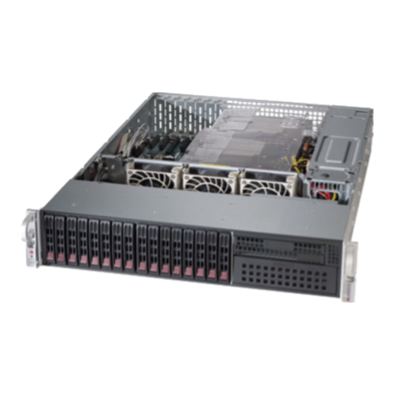
2028R-TXR
USER'S MANUAL
Revision 1.0
Advertisement
Table of Contents

Related Manuals for Supermicro SuperServer 2028R-TXR


Summary of Contents for Supermicro SuperServer 2028R-TXR
- Page 1 Проконсультироваться и купить данное оборудование вы можете в компании «АНД-Системс» адрес: 125480, г.Москва, ул.Туристская, д.33/1; site: https://andpro.ru тел: +7 (495) 545-4870 email: info@andpro.ru При обращении используйте промокод AND-PDF и получите скидку. ® UPER ERVER 2028R-TXR USER’S MANUAL Revision 1.0...
- Page 2 This product, including software and documentation, is the property of Supermicro and/or its licensors, and is supplied only under a license. Any use or reproduction of this product is not allowed, except as expressly permitted by the terms of said license.
-
Page 3: About This Manual
Preface Preface About This Manual This manual is written for professional system integrators and PC technicians. It provides information for the installation and use of the SuperServers. Installation and maintenance should be performed by experienced technicians only. -
Page 4: Table Of Contents
System Power ....................1-3 Front Control Panel ..................1-3 Cooling System ....................1-3 Mounting Rails ....................1-3 Contacting Supermicro ..................1-5 Returning Merchandise for Service..............1-6 Chapter 2 Server Installation Unpacking the System ..................2-1 Preparing for Setup ..................2-1 Choosing a Setup Location ................ - Page 5 Preface Sliding the Chassis onto the Rack Rails ............2-10 Chapter 3 System Interface Overview ......................3-1 Control Panel Buttons ..................3-2 Control Panel LEDs ..................3-2 Overheating ..................... 3-3 Responses ....................3-3 Drive Carrier LEDs ..................3-4 Power Supply LEDs ..................3-4 Chapter 4 Standardized Warning Statements for AC Systems About Standardized Warning Statements ............
- Page 6 UPER ERVER 2028R-TXR User's Manual Memory Support .................... 5-10 Processor & Memory Module Population Confi guration ......5-10 Serverboard Details ..................5-12 Serverboard Quick Reference............... 5-13 Connector Defi nitions ..................5-15 Jumper Settings .................... 5-23 Onboard Indicators ..................5-25 5-10 SATA Connections ..................
- Page 7 Preface Appendix A BIOS Error Beep Codes Appendix B System Specifi cations...
- Page 8 UPER ERVER 2028R-TXR User's Manual Notes viii...
-
Page 9: Chapter 1 Introduction
Product drivers and utilities: ftp://ftp.supermicro.com • Product safety information: http://www.supermicro.com/about/policies/safety_information.cfm For support, email support@supermicro.com. Serverboard Features At the heart of the SuperServer 2028R-TXR lies the X10DRX processor serverboard based upon the Intel PCH C612 chipset. Below are the main features of the serverboard. -
Page 10: Processor
Each serverboard has 16 DIMM slots that can support up to 2TB ECC 3DS of Load Reduced (LRDIMM) registered memory or up to 512GB of registered (RDIMM) DDR4 ECC modules, 2400/2133/1866/1600 MHz. Note: Refer to Section 5-6 before installing memory and the Supermicro website for recommended DIMMs. Onboard SATA A SATA controller is integrated into the chipset for 10 SATA3 (6Gbps) ports that supports RAID 0, 1, 5, and 10. -
Page 11: Chassis Features
Chapter 1: Introduction Chassis Features The following is a general outline of the main features of the SC213XAC-R1K05 server chassis. Hard Drives The SC213 chassis includes sixteen 2.5" hard drive bays and one 5.25'' drive bay. It can accommodate sixteen hot-swap drives. The drives can be hot-swappable if supported by the operating system. -
Page 12: System Block Diagram
UPER ERVER 2028R-TXR User's Manual Figure 1-1. Intel C612 Chipset: System Block Diagram Note: This is a general block diagram. Please see Chapter 5 for details. X10DRX Block Diagram Rev. 1.00 VCCP0&1 12v VR12.5 PCIE-3.0 x8 * 5 PCIE-2.0 x4 * 1 6 PHASE PCIE2.0 x8 Slots 11(x4) 145W... -
Page 13: Contacting Supermicro
Super Micro Computer, Inc. 980 Rock Ave. San Jose, CA 95131 U.S.A. Tel: +1 (408) 503-8000 Fax: +1 (408) 503-8008 Email: marketing@supermicro.com (General Information) support@supermicro.com (Technical Support) Website: www.supermicro.com Europe Address: Super Micro Computer B.V. Het Sterrenbeeld 28, 5215 ML... -
Page 14: Returning Merchandise For Service
For faster service, RMA authorizations may be requested online (http://www. supermicro.com/support/rma/). Whenever possible, repack the chassis in the original Supermicro carton, using the original packaging material. If these are no longer available, be sure to pack the chassis securely, using packaging material to surround the chassis so that it does not shift within the carton and become damaged during shipping. -
Page 15: Chapter 2 Server Installation
Chapter 2: Server Installation Chapter 2 Server Installation This chapter outlines the procedure to install your system into a rack. If your system is not already fully integrated with a drives, processors, or system memory refer to the relevant chapter for details on installing components. Unpacking the System You should inspect the box in which your server was shipped and note if it was damaged. -
Page 16: Warnings And Precautions
UPER ERVER 2028R-TXR User's Manual Warnings and Precautions Rack Precautions • Ensure that the leveling jacks on the bottom of the rack are fully extended to the fl oor with the full weight of the rack resting on them. • In single rack installation, stabilizers should be attached to the rack. -
Page 17: Rack Mounting Considerations
Chapter 2: Server Installation Rack Mounting Considerations Ambient Operating Temperature If installed in a closed or multi-unit rack assembly, the ambient operating tempera- ture of the rack environment may be greater than the ambient temperature of the room. Therefore, consideration should be given to installing the equipment in an environment compatible with the manufacturer’s maximum rated ambient tempera- ture (Tmra). -
Page 18: Checking The Setup
UPER ERVER 2028R-TXR User's Manual Checking the Setup Open the unit to make sure the serverboard is properly installed and all the con- nections have been made. Removing the Chassis Cover 1. Remove the two screws on each side of the cover, which secure the cover to the chassis. -
Page 19: Completing The Confi Guration
Chapter 2: Server Installation Completing the Confi guration Your server may or may not come with hard disk drives, processors or system memory already installed. The following sections refer you to the procedures for installing these components. Checking the Components and Setup •... -
Page 20: Installing The System Into A Rack
UPER ERVER 2028R-TXR User's Manual Installing the System into a Rack This section provides information on installing the chassis into a rack unit with the rails provided. There are a variety of rack units on the market, which may mean that the assembly procedure will differ slightly from the instructions provided. -
Page 21: Releasing The Inner Rail
Chapter 2: Server Installation Releasing the Inner Rail Each inner rail has a locking latch. This latch prevents the server from coming completely out of the rack when when the chassis is pulled out for servicing. To mount the rail onto the chassis, fi rst release the inner rail from the outer rails. Releasing Inner Rail from the Outer Rails 1. -
Page 22: Installing The Inner Rails On The Chassis
UPER ERVER 2028R-TXR User's Manual Installing the Inner Rails on the Chassis Installing the Inner Rails 1. Identify the left and right inner rails. They are labeled. 2. Place the inner rail fi rmly against the side of the chassis, aligning the hooks on the side of the chassis with the holes in the inner rail. -
Page 23: Installing The Outer Rails Onto The Rack
Chapter 2: Server Installation Installing the Outer Rails onto the Rack Installing the Outer Rails 1. Press upward on the locking tab at the rear end of the middle rail. 2. Push the middle rail back into the outer rail. 3. -
Page 24: Sliding The Chassis Onto The Rack Rails
UPER ERVER 2028R-TXR User's Manual Sliding the Chassis onto the Rack Rails Warning: Mounting the system into the rack requires at least two people to support the chassis during installation. Please follow safety recommendations printed on the rails. Installing the Chassis into a Rack 1. -
Page 25: Chapter 3 System Interface
Chapter 3: System Interface Chapter 3 System Interface Overview The server includes: • A control panel on the front that houses power buttons and status monitoring lights • Status lights on the externally accessible hard drives • Status lights for the power supply visible from the back of the chassis Figure 3-1. -
Page 26: Control Panel Buttons
UPER ERVER 2028R-TXR User's Manual Control Panel Buttons The chassis includes two push-buttons that control power to the system. Power: The main power switch is used to apply or remove power from the power supply to the server system. Turning off system power with this button removes the main power but keeps standby power supplied to the system. -
Page 27: Overheating
Chapter 3: System Interface NIC1: Indicates network activity on GLAN1 when fl ashing. Power Fail: Indicates a power supply module has failed. The second power supply module will take the load and keep the system running but the failed module will need to be replaced. -
Page 28: Drive Carrier Leds
UPER ERVER 2028R-TXR User's Manual Drive Carrier LEDs The chassis includes externally accessible SAS/SATA drives. Each drive carrier displays two status LEDs on the front of the carrier. • Green: When illuminated, this LED indicates drive activity. It blinks on and off when that particular drive is being accessed This function is controlled by the backplane. -
Page 29: Chapter 4 Standardized Warning Statements For Ac Systems
The following statements are industry standard warnings, provided to warn the user of situations which have the potential for bodily injury. Should you have questions or experience difficulty, contact Supermicro's Technical Support department for assistance. Only certifi ed technicians should attempt to install or confi gure components. - Page 30 UPER ERVER 2028R-TXR User's Manual Warnung WICHTIGE SICHERHEITSHINWEISE Dieses Warnsymbol bedeutet Gefahr. Sie befi nden sich in einer Situation, die zu Verletzungen führen kann. Machen Sie sich vor der Arbeit mit Geräten mit den Gefahren elektrischer Schaltungen und den üblichen Verfahren zur Vorbeugung vor Unfällen vertraut.
- Page 31 Warning Statements for AC Systems ﺟﺴﺪﻳﺔ ﺍﺻﺎﺑﺔ ﺗﺘﺴﺒﺐ ﻓﻲ ﺣﺎﻟﺔ ﻳﻤﻜﻦ ﺃﻥ ﺍﻧﻚ ﻓﻲ ﺧﻄﺮ ﻳﻌﻨﻲ ﻫﺬﺍ ﺍﻟﺮﻣﺰ !ﺗﺤﺬﻳﺮ ﺍﻟﺪﻭﺍﺋﺮ ﺑﺎﻟﻤﺨﺎﻁﺮ ﺍﻟﻨﺎﺟﻤﺔ ﻋﻦ ﻦ ﻋﻠﻰ ﻋﻠﻢ ، ﻛ ﻣﻌﺪﺍﺕ ﺗﻌﻤﻞ ﻋﻠﻰ ﺃﻱ ﻗﺒﻞ ﺃﻥ ﺍﻟﻜﻬﺮﺑﺎﺋﻴﺔ ﺣﻮﺍﺩﺙ ﺃﻱ ﻭﻗﻮﻉ ﻤﻨﻊ ﻟ ﺍﻟﻮﻗﺎﺋﻴﺔ...
-
Page 32: Installation Instructions
UPER ERVER 2028R-TXR User's Manual Installation Instructions Warning! Read the installation instructions before connecting the system to the power source. 設置手順書 システムを電源に接続する前に、 設置手順書をお読み下さい。 警告 将此系统连接电源前,请先阅读安装说明。 警告 將系統與電源連接前,請先閱讀安裝說明。 Warnung Vor dem Anschließen des Systems an die Stromquelle die Installationsanweisungen lesen. ¡Advertencia! Lea las instrucciones de instalación antes de conectar el sistema a la red de alimentación. -
Page 33: Circuit Breaker
Chapter 4: Warning Statements for AC Systems Circuit Breaker Warning! This product relies on the building's installation for short-circuit (overcurrent) protection. Ensure that the protective device is rated not greater than: 250 V, 20 A. サーキッ ト ・ ブレーカー この製品は、 短絡 (過電流) 保護装置がある建物での設置を前提としています。 保護装置の定格が250 V、... -
Page 34: Power Disconnection Warning
UPER ERVER 2028R-TXR User's Manual 경고! 이 제품은 전원의 단락(과전류)방지에 대해서 전적으로 건물의 관련 설비에 의존합니다. 보호장치의 정격이 반드시 250V(볼트), 20A(암페어)를 초과하지 않도록 해야 합니다. Waarschuwing Dit product is afhankelijk van de kortsluitbeveiliging (overspanning) van uw electrische installatie. Controleer of het beveiligde aparaat niet groter gedimensioneerd is dan 220V, 20A. - Page 35 Chapter 4: Warning Statements for AC Systems ¡Advertencia! El sistema debe ser disconnected de todas las fuentes de energía y del cable eléctrico quitado de los módulos de fuente de alimentación antes de tener acceso el interior del chasis para instalar o para quitar componentes de sistema. Attention Le système doit être débranché...
-
Page 36: Equipment Installation
UPER ERVER 2028R-TXR User's Manual Equipment Installation Warning! Only trained and qualifi ed personnel should be allowed to install, replace, or service this equipment. 機器の設置 トレーニングを受け認定された人だけがこの装置の設置、 交換、 またはサービスを許可 されています。 警告 只有经过培训且具有资格的人员才能进行此设备的安装、更换和维修。 警告 只有經過受訓且具資格人員才可安裝、更換與維修此設備。 Warnung Das Installieren, Ersetzen oder Bedienen dieser Ausrüstung sollte nur geschultem, qualifi... -
Page 37: Restricted Area
Chapter 4: Warning Statements for AC Systems Waarschuwing Deze apparatuur mag alleen worden geïnstalleerd, vervangen of hersteld door geschoold en gekwalifi ceerd personeel. Restricted Area Warning! This unit is intended for installation in restricted access areas. A restricted access area can be accessed only through the use of a special tool, lock and key, or other means of security. -
Page 38: Battery Handling
UPER ERVER 2028R-TXR User's Manual אזור עם גישה מוגבלת !אזהרה יש להתקין את היחידה באזורים שיש בהם הגבלת גישה. הגישה ניתנת בעזרת .('כלי אבטחה בלבד )מפתח, מנעול וכד ﻣﺤﻈﻮﺭﺓ ﻣﻨﺎﻁﻖ ﻟﺘﺮﻛﻴﺒﻬﺎ ﻓﻲ ﻫﺬﻩ ﺍﻟﻮﺣﺪﺓ ﺗﺨﺼﻴﺺ ﺗﻢ ،ﺃﺩﺍﺓ ﺧﺎﺻﺔ ﻣﻦ ﺧﻼﻝ ﺍﺳﺘﺨﺪﺍﻡ ﻓﻘﻂ... - Page 39 Chapter 4: Warning Statements for AC Systems Warnung Bei Einsetzen einer falschen Batterie besteht Explosionsgefahr. Ersetzen Sie die Batterie nur durch den gleichen oder vom Hersteller empfohlenen Batterietyp. Entsorgen Sie die benutzten Batterien nach den Anweisungen des Herstellers. Attention Danger d'explosion si la pile n'est pas remplacée correctement. Ne la remplacer que par une pile de type semblable ou équivalent, recommandée par le fabricant.
-
Page 40: Redundant Power Supplies
UPER ERVER 2028R-TXR User's Manual Redundant Power Supplies Warning! This unit might have more than one power supply connection. All connections must be removed to de-energize the unit. 冗長電源装置 このユニッ トは複数の電源装置が接続されている場合があります。 ユニッ トの電源を切るためには、 すべての接続を取り外さなければなりません。 警告 此部件连接的电源可能不止一个,必须将所有电源断开才能停止给该部件供电。 警告 此裝置連接的電源可能不只一個,必須切斷所有電源才能停止對該裝置的供電。 Warnung Dieses Gerät kann mehr als eine Stromzufuhr haben. Um sicherzustellen, dass der Einheit kein trom zugeführt wird, müssen alle Verbindungen entfernt werden. -
Page 41: Backplane Voltage
Chapter 4: Warning Statements for AC Systems ﺍﻣﺪﺍﺩ ﺍﻟﻄﺎﻗﺔ ﺑﻮﺣﺪﺍﺕ ﻋﺪﺓ ﺍﺗﺼﺎﻻﺕ ﺠﻬﺎﺯ ﺍﻟ ﻳﻜﻮﻥ ﻟﻬﺬﺍ ﻗﺪ ﺍﻟﻜﻬﺮﺑﺎء ﻋﻦ ﻮﺣﺪﺓ ﺍﻟ ﻟﻌﺰﻝ ﻛﺎﻓﺔ ﺍﻻﺗﺼﺎﻻﺕ ﻳﺠﺐ ﺇﺯﺍﻟﺔ 경고! 이 장치에는 한 개 이상의 전원 공급 단자가 연결되어 있을 수 있습니다. 이 장치에 전원을... -
Page 42: Comply With Local And National Electrical Codes
UPER ERVER 2028R-TXR User's Manual מתח בפנל האחורי !הרה אז קיימת סכנת מתח בפנל האחורי בזמן תפעול המערכת. יש להיזהר במהלך .העבודה ﺍﻟﻠﻮﺣﺔ ﺃﻭﺍﻟﻄﺎﻗﺔ ﺍﻟﻤﻮﺟﻮﺩﺓ ﻋﻠﻰ ﺍﻟﺘﻴﺎﺭ ﺍﻟﻜﻬﺮﺑﺎﺋﻲ ﻣﻦ ﺧﻄﺮ ﻫﻨﺎﻙ ﻫﺬﺍ ﺍﻟﺠﻬﺎﺯ ﺧﺪﻣﺔ ﻛﻦ ﺣﺬﺭﺍ ﻋﻨﺪ ﻳﻌﻤﻞ ﺍﻟﻨﻈﺎﻡ ﻋﻨﺪﻣﺎ ﻳﻜﻮﻥ 경고! 시스템이... -
Page 43: Product Disposal
Chapter 4: Warning Statements for AC Systems Attention L'équipement doit être installé conformément aux normes électriques nationales et locales. תיאום חוקי החשמל הארצי !אזהרה הציוד חייבת להיות תואמת לחוקי החשמל המקומיים והארציים התקנת ﺍﻟﻤﺘﻌﻠﻘﺔ ﺍﻟﻤﺤﻠﻴﺔ ﻭﺍﻟﻮﻁﻨﻴﺔ ﻘﻮﺍﻧﻴﻦ ﻳﺠﺐ ﺃﻥ ﻳﻤﺘﺜﻞ ﻟﻠ ﺍﻟﻜﻬﺮﺑﺎﺋﻴﺔ... -
Page 44: Hot Swap Fan Warning
UPER ERVER 2028R-TXR User's Manual Attention La mise au rebut ou le recyclage de ce produit sont généralement soumis à des lois et/ou directives de respect de l'environnement. Renseignez-vous auprès de l'organisme compétent. סילוק המוצר !אזהרה .חוקי המדינה סילוק סופי של מוצר זה חייב להיות בהתאם להנחיות ו ﺍﻟﻘﻮﺍﻧﻴﻦ... - Page 45 Chapter 4: Warning Statements for AC Systems Warnung Gefährlich Bewegende Teile. Von den bewegenden Lüfterblätter fern halten. Die Lüfter drehen sich u. U. noch, wenn die Lüfterbaugruppe aus dem Chassis genommen wird. Halten Sie Finger, Schraubendreher und andere Gegenstände von den Öffnungen des Lüftergehäuses entfernt. ¡Advertencia! Riesgo de piezas móviles.
-
Page 46: Power Cable And Ac Adapter
fi re. Electrical Appliance and Material Safety Law prohibits the use of UL or CSA -certifi ed cables (that have UL/CSA shown on the code) for any other electrical devices than products designated by Supermicro only. 電源コードとACアダプター... - Page 47 Appareils électroménagers et de loi sur la sécurité Matériel interdit l'utilisation de UL ou CSA câbles certifi és qui ont UL ou CSA indiqué sur le code pour tous les autres appareils électriques que les produits désignés par Supermicro seulement.
- Page 48 UPER ERVER 2028R-TXR User's Manual Notes 4-20...
-
Page 49: Chapter 5 Advanced Serverboard Setup
Chapter 5: Advanced Serverboard Setup Chapter 5 Advanced Serverboard Setup This chapter covers the steps required to install processors and heatsinks to the X10DRX serverboard, connect the data and power cables and install add-on cards. All serverboard jumpers and connections are described and a layout and quick reference chart are included in this chapter. -
Page 50: Installing The Processor And Heatsink
• Install the processor into the CPU socket before installing the heatsink. • Refer to the Supermicro website for updates on CPU support. Installing an LGA 2011 Processor Installing a CPU 1. There are two load levers on the LGA 2011 socket. - Page 51 Chapter 5: Advanced Serverboard Setup 3. With the sec ond lever fully Open the load plate. retracted, gently push down on the "Open 1st" lever to loosen the load plate. Lift the load plate with your fi ngers to open it completely. 4.
- Page 52 UPER ERVER 2028R-TXR User's Manual Gently close the load plate. 7. With the "Close 1st" lever fully retracted, gently close the load plate. Push down and lock the lever labeled "Close 1st". 8. Make sure the locking mechanism on the "Close 1st" lever catches the lip of the load plate.
-
Page 53: Installing A Passive Cpu Heatsink
Chapter 5: Advanced Serverboard Setup Installing a Passive CPU Heatsink 1. Apply the proper amount of thermal grease to the heatsink. 2. Place the heatsink on top of the CPU so that the two mounting holes on the heatsink are aligned with those on the retention mechanism. 3. -
Page 54: Removing The Passive Heatsink
UPER ERVER 2028R-TXR User's Manual Removing the Passive Heatsink Warning: We do not recommend that the CPU or the heatsink be removed. However, if you do need to remove the heatsink, please follow the instructions below to uninstall the heatsink to avoid damaging the CPU or other components. 1. -
Page 55: Connecting Cables
Chapter 5: Advanced Serverboard Setup Connecting Cables Now that the processors are installed, the next step is to connect the cables to the serverboard. These include the data cables for the peripherals and control panel and the power cables. Connecting Data Cables The cables used to transfer data from the peripheral devices have been carefully routed in preconfi... -
Page 56: I/O Ports
UPER ERVER 2028R-TXR User's Manual I/O Ports Figure 5-3 shows the I/O ports on the rear of the system. Figure 5-3. Rear Panel I/O Ports 1. COM Port 1 (Turquoise) 2. Back Panel USB 3.0 Port 4 3. Back Panel USB 3.0 Port 5 4. -
Page 57: Installing Memory
Chapter 5: Advanced Serverboard Setup Installing Memory Note: Check the Supermicro website for recommended memory modules. CAUTION Exercise extreme care when installing or removing DIMM modules to prevent any possible damage. Installing DIMMs 1. Insert the desired number of DIMMs into the memory slots, starting with slot DIMMA1. -
Page 58: Super Server 2028R-Txr User's Manual
(LRDIMM) or up to 512 GB of Registered (RDIMM) ECC 2400/2133/1866/1600 MHz modules. For the latest memory updates, please refer to our website at http://www. supermicro.com/products/motherboard. Processor & Memory Module Population Confi guration For memory to work properly, follow the tables below for memory installation. - Page 59 Chapter 5: Advanced Serverboard Setup Caution: For the memory to work properly, install DIMMs of the same type and speed. Mixing of DIMMs of different types or speeds is not allowed. Populating DDR4 Memory Modules for the E5-2600v4-based Motherboard Populating RDIMM/LRDIMM DDR4 Memory Modules Speed (MT/s);...
-
Page 60: Serverboard Details
UPER ERVER 2028R-TXR User's Manual Serverboard Details IPMI LAN UID-SW COM1 LAN2 USB 0/1 (2.0) USB 4/5 (3.0) LAN1 JUIDB1 UID-LED LED1 FAN5 FAN4 FANC LAN CTRL BMC CTRL BMC FWR LEM1 CPU2 X10DRX Rev. 100 BIOS FAN7 CPU2 CPU1 JBAT1 Battery JBT1... -
Page 61: Serverboard Quick Reference
Chapter 5: Advanced Serverboard Setup Serverboard Quick Reference Jumpers Jumper Description Default Setting JBT1 Reset BIOS Confi guration See Section 5-8 C1/JI SMB to PCI-E Slots Pins 2-3 (Disabled) JPB1 BMC Enable Pins 1-2 (Enabled) JPG1 VGA Enable Pins 1-2 (Enabled) JPL1 LAN1/2 Enable Pins 1-2 (Enabled) - Page 62 UPER ERVER 2028R-TXR User's Manual (BP) USB 0/1 (2.0) Backpanel USB 2.0 Ports 0/1 (BP) USB 2/3 (2.0) Front accessible USB 2.0 connection 2/3 header (FP) USB 4/5 (3.0) Backpanel USB 3.0 ports 4/5 (FP) USB 6 (3.0) Front accessible Type A USB 3.0 port 6 (FP) USB 7/8 (3.0) Front accessible USB 3.0 connection 7/8 Header Backpanel VGA Port...
-
Page 63: Connector Defi Nitions
Chapter 5: Advanced Serverboard Setup Connector Defi nitions Serial Ports Serial Port (COM2) Pin Defi nitions Two COM connections (COM1 & Pin # Defi nition Pin # Defi nition COM2) are located on the mother- board. COM1 is located on the Back- plane I/O panel. - Page 64 I/O back panel. Note: UID can also be triggered via IPMI on the motherboard. For more information on IPMI, please refer to the IPMI User's Guide posted on our website at http://www.supermicro.com. 5-16...
- Page 65 Chapter 5: Advanced Serverboard Setup Power Connectors ATX Power 24-pin Connector Pin Defi nitions (JPW1) A 24-pin main power supply connector Pin# Defi nition Pin # Defi nition ( J P W R 1 ) , t w o 8 - p i n C P U p o w e r +3.3V +3.3V connectors (JPWR2/JPWR3), and a...
- Page 66 Two external powered SATADOM (Device-on-Module) power connec- Ground tors are located at JSD1/JSD2 on the Ground motherboard.These connectors provide backward-compatible power support to non-Supermicro SATADOMs that require external power supply. IPMB IPMB Header Pin Defi nitions A System Management Bus (SMB) Pin# Defi...
- Page 67 Chapter 5: Advanced Serverboard Setup I-SGPIO1/2 & S-SGPIO1 Headers I-SGPIO1/2 & S-SGPIO1 Headers Pin Defi nitions Three SGPIO (Serial-Link General Pur- Pin # Defi nition Pin # Defi nition pose Input/Output) headers are located on the motherboard. I-SGPIO1/2 support Ground Data onboard I-SATA 0-5, and S-SGPIO sup- Load...
- Page 68 UPER ERVER 2028R-TXR User's Manual NMI Button NMI Button Pin Defi nitions (JF1) The non-maskable interrupt button Pin# Defi nition header is located on pins 19 and 20 Control of JF1. Refer to the table on the right Ground for pin defi nitions. Power LED Power LED Pin Defi...
- Page 69 Chapter 5: Advanced Serverboard Setup Power Fail LED PWR Fail LED Pin Defi nitions (JF1) The Power Fail LED connection is Pin# Defi nition located on pins 5 and 6 of JF1. Re- 3.3V fer to the table on the right for pin PWR Supply Fail defi...
- Page 70 Note: UID can also be triggered via Reset Reset Button Ground IPMI on the motherboard. For more Power Button Ground information on IPMI, please refer to Front Control Panel (JF1) the IPMI User's Guide posted on our website at http://www.supermicro. com. 5-22...
-
Page 71: Jumper Settings
Chapter 5: Advanced Serverboard Setup Jumper Settings Explanation of Jumpers To modify the operation of the serverboard, jumpers can be used Connector to choose between optional settings. Pins Jumpers create shorts between two pins to change the function of the Jumper connector. - Page 72 UPER ERVER 2028R-TXR User's Manual Watch Dog Enable/Disable Watch Dog Jumper Settings Watch Dog (JWD1) is a system moni- Jumper Setting Defi nition tor that will reboot the system when Pins 1-2 Reset (Default) a software application hangs. Close Pins 2-3 pins 1-2 to reset the system if an ap- Open Disabled...
-
Page 73: Onboard Indicators
Chapter 5: Advanced Serverboard Setup Onboard Indicators LAN 1/2 LEDs Activity LED Link LED Two LAN ports (LAN 1/LAN 2) are located on the I/O back panel of the motherboard. LAN 1/LAN 2 Activity LED (Right) Each Ethernet LAN port has two LEDs. LED State The green LED indicates activity, while Color... -
Page 74: 5-10 Sata Connections
Ten SATA 3.0 ports (I-SATA0-5, S-SATA0-3) are located on the motherboard. I-SATA0-5 are supported by the Intel PCH, and S-SATA0-3 are supported by the Intel SCU. I-SATA4/5 can be used with Supermicro SuperDOMs which are yellow SATA DOM connectors with power pins built in, and do not require external power cables. -
Page 75: 5-11 Installing Software
Chapter 5: Advanced Serverboard Setup 5-11 Installing Software The Supermicro ftp site contains drivers and utilities for your system at ftp://ftp. supermicro.com. Some of these must be installed, such as the chipset driver. After accessing the ftp site, go into the CDR_Images directory and locate the ISO fi... -
Page 76: Superdoctor ® 5
ERVER 2028R-TXR User's Manual SuperDoctor ® The Supermicro SuperDoctor 5 is a program that functions in a command-line or web-based interface in Windows and Linux operating systems. The program monitors system health information such as CPU temperature, system voltages, system power consumption, fan speed, and provides alerts via email or Simple Network Management Protocol (SNMP). -
Page 77: 5-12 Onboard Battery
Chapter 5: Advanced Serverboard Setup 5-12 Onboard Battery Please handle used batteries carefully. Do not damage the battery in any way; a damaged battery may release hazardous materials into the environment. Do not discard a used battery in the garbage or a public landfi ll. Please comply with the regulations set up by your local hazardous waste management agency to dispose of your used battery properly. - Page 78 UPER ERVER 2028R-TXR User's Manual Notes 5-30...
-
Page 79: Chapter 6 Advanced Chassis Setup
Chapter 6: Advanced Chassis Setup Chapter 6 Advanced Chassis Setup This chapter provides the procedures to install components and perform main- tenance on the SC213XAC-R1K05 chassis. The only tool required is a Phillips screwdriver. Your system may require the installation of processors, memory, drives or expan- sion cards. - Page 80 UPER ERVER 2028R-TXR User's Manual PCI-E 2.0x4 (LP) Slot 10 PCI-E 3.0x8 (LP) Slots Dual CPU Intel ® Xeon ® E5-2600 v4/v3 up to 160W USB Port 16 DIMM Slots DDR4 2 SuperDOM Ports 4 Internal Fans Figure 6-2. Top Chassis View...
-
Page 81: Static-Sensitive Devices
These carriers also help promote proper airfl ow for the drive bays. The hard disk drive are sold separately. Enterprise level hard disk drives are recommended for use in Supermicro chassis and servers. For information on recommended HDDs, visit the Supermicro website at http://www.supermicro.com/... - Page 82 UPER ERVER 2028R-TXR User's Manual Removing Hard Drive Carriers from the Chassis 1. Press the release button on the drive carrier. This extends the drive bay handle. 2. Use the handle to pull the drive out of the chassis. 3. Remove the dummy drive from the carrier (Figure 6-3). Figure 6-3.
- Page 83 Chapter 6: Advanced Chassis Setup Dummy Drive Drive Carrier Figure 6-4. Removing a Dummy Drive from Carrier Installing a Drive into the Carrier 1. Install a new drive into the carrier with the printed circuit board side facing down so that the mounting holes in the drive align with those in the carrier. 2.
-
Page 84: Peripheral Drive Installation
The chassis includes a 5.25' bay for a variety of peripheral drive options, including a slim DVD drive or an additional hard disk drive. For a complete listing of peripheral drive options, visit the Supermicro website. Installing or Replacing a Peripheral Drive 1. -
Page 85: Installing Expansion Cards
Chapter 6: Advanced Chassis Setup Installing Expansion Cards The 2028R-TXR system includes eleven slots for expansion cards. The serverboard must be installed before expansion cards. Installing an Expansion Card for an LP Model Chassis 1. Power down the system and remove the cover. 2. -
Page 86: Installing The Air Shroud
Installing the Air Shroud 1. Confi rm that your air shroud matches your chassis model. For ordering infor- mation, visit the Supermicro website at www.supermicro.com and click on the Where to Buy link. 2. Place the air shroud in the chassis. It fi ts behind the two fans closest to the power supply. -
Page 87: System Fans
Chapter 6: Advanced Chassis Setup System Fans Three heavy duty fans provide cooling for the system components. Replacing a System Fan 1. If necessary, open the chassis while the power is running to determine which fan has failed. (Never run the server for an extended period of time with the chassis open.) 2. - Page 88 UPER ERVER 2028R-TXR User's Manual Figure 6-9. Placing a System Fan 5. Place the new fan into the vacant space in the housing while making sure the arrows on the top of the fan (indicating air direction) point in the same direction as the arrows on the other fans.
-
Page 89: Installing The Serverboard
Chapter 6: Advanced Chassis Setup Installing the Serverboard I/O Shield Figure 6-10. I/O Shield Placement I/O Shield The I/O shield holds the serverboard ports in place. Install the I/O shield before installing the serverboard. Installing the I/O Shield Installing the I/O Shield 1. -
Page 90: Permanent And Optional Standoffs
UPER ERVER 2028R-TXR User's Manual Permanent and Optional Standoffs Standoffs prevent short circuits by securing space between the serverboard and the chassis surface. The chassis includes permanent standoffs in locations used by most serverboards. These standoffs accept the rounded Phillips head screws included in the accessories packaging. -
Page 91: Power Supply
An amber light on the power supply is illuminated when the power is switched off. An green light indicates that the power supply is operating. Replacement units can be ordered directly from Supermicro. Replace a failed power supply module with the same model. - Page 92 UPER ERVER 2028R-TXR User's Manual Replacing the Power Supply 1. Unplug the AC cord from the module you want to replace. 2. Push the release tab on the back of the power supply, as illustrated. 3. Pull the power supply out using the handle. 4.
-
Page 93: Chapter 7 Bios
When an option is selected in the left frame, it is highlighted in white. Often a text message will accompany it. Note: the AMI BIOS has default text messages built in. Supermicro retains the option to include, omit, or change any of these text messages. -
Page 94: Starting The Setup Utility
Flashing the wrong BIOS can cause irreparable damage to the system. In no event shall Supermicro be liable for direct, indirect, special, incidental, or consequential damages arising from a BIOS update. If you have to update the BIOS, do not shut down or reset the system while the BIOS is updating to avoid possible boot failure. - Page 95 This item displays the system date in Day MM/DD/YY format (e.g. Wed 10/12/2011). System Time This item displays the system time in HH:MM:SS format (e.g. 15:32:52). Supermicro X10DRX BIOS Version This item displays the version of the BIOS ROM used in this system.
-
Page 96: Advanced Setup Confi Gurations
UPER ERVER 2028R-TXR User's Manual Advanced Setup Confi gurations Use the arrow keys to select Advanced Setup and press <Enter> to access the following submenu items. Boot Features Quiet Boot Use this item to select the bootup screen display between POST messages and the OEM logo. - Page 97 Chapter 7: BIOS INT19 (Interrupt 19) Trap Response Interrupt 19 is the software interrupt that handles the boot disk function. When this item is set to Immediate, the ROM BIOS of the host adaptors will "capture" Interrupt 19 at bootup immediately and allow the drives that are attached to the host adap- tors to function as bootable disks.
- Page 98 UPER ERVER 2028R-TXR User's Manual CPU Confi guration This submenu displays the information of a CPU as detected by the BIOS. It also allows the user to confi guration CPU settings. Socket 1 CPU Information/Socket 2 CPU Information This submenu displays the following information regarding the CPU installed in Socket 1 and (or) Socket 2 as detected by the BIOS.
- Page 99 Chapter 7: BIOS Execute Disable Bit (Available if supported by the OS & the CPU) Select Enable to enable the Execute-Disable Bit which will allow the processor to designate an area in the system memory where an application code can execute and where it cannot, thus preventing a worm or a virus from fl...
- Page 100 UPER ERVER 2028R-TXR User's Manual Intel® Virtualization Technology (Available when supported by the CPU) Select Enable to support Intel Virtualization Technology, which will allow one platform to run multiple operating systems and applications in independent parti- tions, creating multiple "virtual" systems in one physical computer. The options are Enable and Disable.
-
Page 101: Cpu P State Control
Chapter 7: BIOS CPU P State Control EIST (P-States) EIST (Enhanced Intel SpeedStep Technology) allows the system to automatically adjust processor voltage and core frequency to reduce power consumption and heat dissipation. The options are Disable and Enable. Turbo Mode (Available when Intel® EIST Technology is enabled) Select Enable to use the Turbo Mode to boost system performance. -
Page 102: Cpu T State Control
UPER ERVER 2028R-TXR User's Manual CPU T State Control ACPI (Advanced Confi guration Power Interface) T-States Select Enable to support CPU throttling by the operating system to reduce power consumption. The options are Enable and Disable. Chipset Confi guration North Bridge This feature allows the user to confi... - Page 103 Chapter 7: BIOS CPU1 SLOT2 PCI-E 3.0 x8 Link Speed This item confi gures the link speed of a PCI-E port specifi ed by the user. The options are Gen 1 (Generation 1) (2.5 GT/s), Gen 2 (Generation 2) (5 GT/s), and Gen 3 (Generation 3) (8 GT/s).
- Page 104 UPER ERVER 2028R-TXR User's Manual CPU2 SLOT8 PCI-E 3.0 x8 Link Speed This item confi gures the link speed of a PCI-E port specifi ed by the user. The options are Gen 1 (Generation 1) (2.5 GT/s), Gen 2 (Generation 2) (5 GT/s), and Gen 3 (Generation 3) (8 GT/s).
- Page 105 Chapter 7: BIOS Intel VT for Directed I/O (VT-d) ® Intel VT for Directed I/O (VT-d) Select Enable to use Intel Virtualization Technology support for Direct I/O VT-d support by reporting the I/O device assignments to the VMM (Virtual Machine Monitor) through the DMAR ACPI Tables.
- Page 106 UPER ERVER 2028R-TXR User's Manual COD Enable (Available when the OS and the CPU support this feature) Select Enable for Cluster-On-Die support to enhance system performance in cloud computing. The options are Enable and Disable. Early Snoop (Available when the OS and the CPU support this feature) Select Enable for Early Snoop support to enhance system performance.
-
Page 107: Dimm Information
Chapter 7: BIOS Set Throttling Mode Throttling improves reliability and reduces power consumption in the proces- sor via automatic voltage control during processor idle states. The options are Disabled and CLTT (Closed Loop Thermal Throttling). A7 Mode Select Enable to support A7 (Addressing) mode to improve memory performance. The options are Enable and Disable. - Page 108 UPER ERVER 2028R-TXR User's Manual Demand Scrub Demand Scrubbing is a process that allows the CPU to correct correctable memory errors found on a memory module. When the CPU or I/O issues a demand-read command, and the read data from memory turns out to be a correctable error, the error is corrected and sent to the requestor (the original source).
- Page 109 Chapter 7: BIOS USB 3.0 Support Select Enabled for USB 3.0 support. The options are Smart Auto, Auto, Enabled, Disabled and Manual. EHCI1 Select Enabled to enable EHCI (Enhanced Host Controller Interface) support on USB 2.0 connector #1 (-at least one USB 2.0 connector should be enabled for EHCI support.) The options are Disabled and Enabled.
- Page 110 UPER ERVER 2028R-TXR User's Manual SATA Port 0~ Port 5 This item displays the information detected on the installed SATA drive on the particular SATA port. • Model number of drive and capacity • Software Preserve Support SATA Port 0~ Port 5 Select Enabled to enable a SATA port specifi...
- Page 111 Chapter 7: BIOS Support Aggressive Link Power Management When this item is set to Enabled, the SATA AHCI controller manages the power usage of the SATA link. The controller will put the link to a low power state when the I/O is inactive for an extended period of time, and the power state will return to normal when the I/O becomes active.
- Page 112 UPER ERVER 2028R-TXR User's Manual Port 0 ~ Port 5 SATA Device Type Use this item to specify if the SATA port specifi ed by the user should be con- nected to a Solid State drive or a Hard Disk Drive. The options are Hard Disk Drive and Solid State Drive.
- Page 113 Chapter 7: BIOS sSATA Port 0 ~ Port 3 Hot Plug Select Enabled to enable hot-plugging support for a port specifi ed by the user, which will allow the user to replace a SATA disk drive installed on this port without shutting down the system.
- Page 114 UPER ERVER 2028R-TXR User's Manual Please note that the option-Both is not supported by the Windows Server 2012/ R2 OS. The options are Both, SATA Controller, and sSATA Controller. sSATA Port 0~ Port 3 This item displays the information detected on the installed sSATA drives on the particular sSATA port.
- Page 115 Chapter 7: BIOS • Current State • Error Code PCIe/PCI/PnP Confi guration The following PCI information will be displayed: PCI Bus Driver Version PCI Devices Common Settings: PCI PERR/SERR Support Select Enabled for the system to log an error event when a PERR (PCI/PCI-E Parity Error) or a SERR (System Error) occurs.
- Page 116 UPER ERVER 2028R-TXR User's Manual MMIOHBase Use this item to select the base memory size according to memory-address map- ping for the IO hub. The base memory size must be between 4032G to 4078G. The options are 56T, 48T, 24T, 512G, and 256G. MMIO High Size Use this item to select the high memory size according to memory-address mapping for the IO hub.
-
Page 117: Serial Port Console Redirection
Chapter 7: BIOS Super IO Confi guration Super IO Chip AST2400 Serial Port 1 Confi guration/Serial Port 2 Confi guration Serial Port 1/Serial Port 2 Select Enabled to enable the onboard serial port specifi ed by the user. The options are Enabled and Disabled. - Page 118 UPER ERVER 2028R-TXR User's Manual COM1 Console Redirection Settings Terminal Type This feature allows the user to select the target terminal emulation type for Con- sole Redirection. Select VT100 to use the ASCII Character set. Select VT100+ to add color and function key support. Select ANSI to use the Extended ASCII Char- acter Set.
- Page 119 Chapter 7: BIOS Recorder Mode Select Enabled to capture the data displayed on a terminal and send it as text messages to a remote server. The options are Disabled and Enabled. Resolution 100x31 Select Enabled for extended-terminal resolution support. The options are Dis- abled and Enabled.
- Page 120 UPER ERVER 2028R-TXR User's Manual Bits Per second Use this feature to set the transmission speed for a serial port used in Console Redirection. Make sure that the same speed is used in the host computer and the client computer. A lower transmission speed may be required for long and busy lines.
- Page 121 Chapter 7: BIOS Legacy OS Redirection Resolution Use this feature to select the number of rows and columns used in Console Redirection for legacy OS support. The options are 80x24 and 80x25. Putty KeyPad Use this item to confi gure the settings for the function keys and the key pad for Putty, which is a terminal emulator designed for the Windows OS.
-
Page 122: Acpi Settings
UPER ERVER 2028R-TXR User's Manual Bits Per Second This item sets the transmission speed for a serial port used in Console Redirec- tion. Make sure that the same speed is used in both host computer and the client computer. A lower transmission speed may be required for long and busy lines. The options are 9600, 19200, 57600, and 115200 (bits per second). - Page 123 TPM Owner Status TXT Support Select Enabled to enable TXT (Trusted Execution Technology) settings to improve data and network security. The options are Disabled and Enabled. Note: For more information on TPM, please refer to the TPM manual at http://www.supermicro.com/manuals/other/TPM.pdf. 7-31...
-
Page 124: Event Logs
UPER ERVER 2028R-TXR User's Manual Event Logs Use this feature to confi gure Event Log settings. Change SMBIOS Event Log Settings This feature allows the user to confi gure SMBIOS Event settings. Enabling/Disabling Options SMBIOS Event Log Select Enabled to enable SMBIOS (System Management BIOS) Event Logging during system boot. -
Page 125: View Smbios Event Log
Chapter 7: BIOS SMBIOS Event Log Standard Settings Log System Boot Event Select Enabled to log system boot events. The options are Disabled and Enabled. MECI (Multiple Event Count Increment) Enter the increment value for the multiple event counter. Enter a number between 1 to 255. -
Page 126: Ipmi
UPER ERVER 2028R-TXR User's Manual IPMI Use this feature to confi gure Intelligent Platform Management Interface (IPMI) settings. IPMI Firmware Revision This item indicates the IPMI fi rmware revision used in your system. IPMI Status This item indicates the status of the IPMI fi rmware installed in your system. ... - Page 127 Chapter 7: BIOS When SEL is Full This feature allows the user to determine what the BIOS should do when the sys- tem event log is full. Select Erase Immediately to erase all events in the log when the system event log is full. The options are Do Nothing and Erase Immediately. Note: After making changes on a setting, be sure to reboot the system for the changes to take effect.
-
Page 128: Security Settings
UPER ERVER 2028R-TXR User's Manual Security Settings This menu allows the user to confi gure the following security settings for the system. Password Check Select Setup for the system to prompt for a password at upon entering the BIOS setup utility. Select Always for the system to prompt for a password at bootup and upon entering the BIOS setup utility. -
Page 129: Secure Boot Menu
Chapter 7: BIOS Secure Boot Menu Secure Boot Select Enable for secure boot support to ensure system security at bootup. The options are Enabled and Disabled. Secure Boot Mode This feature allows the user to select the desired secure boot mode for the system. The options are Standard and Custom. - Page 130 UPER ERVER 2028R-TXR User's Manual Append KEK (Key Exchange Key) Select <Yes> to load the new KEK from the manufacture defaults. Select <No> to load the new KEK from other sources. Authorized Signatures Delete DB (DataBase) Select <Yes> to confi rm deletion of a database from the system. ...
-
Page 131: Boot Settings
Chapter 7: BIOS Boot Settings Use this feature to confi gure Boot Settings: Boot Confi guration Setup Prompt Timeout Use this item to indicate how many seconds the system shall wait for the BIOS setup activation key to respond before the system starts to boot. The default setting is 1. Boot Mode Select Use this item to select the type of device to be used for system boot. - Page 132 UPER ERVER 2028R-TXR User's Manual Delete Boot Option Use this item to select a boot device to delete from the boot priority list. Delete Boot Option Select the target boot device to delete. Network Drive BBS Priorities • Legacy Boot Order #1 7-40...
-
Page 133: Save & Exit
Chapter 7: BIOS Save & Exit Select the Save & Exit tab from the BIOS setup screen to confi gure the settings below. Discard Changes and Exit Select this option to quit the BIOS setup without making any permanent changes to the system confi... - Page 134 UPER ERVER 2028R-TXR User's Manual Restore Defaults Select Restore Defaults from the Exit menu and press <Enter> to load manufacture default settings for your system to maximize system performance but not stability. Save As User Defaults Select Save as User Defaults from the Exit menu and press <Enter> to save changes to the BIOS setup for future use.
-
Page 135: Bios Error Beep Codes
Appendix A: BIOS Error Beep Codes Appendix A BIOS Error Beep Codes During the POST (Power-On Self-Test) routines, which are performed each time the system is powered on, errors may occur. Non-fatal errors are those which, in most cases, allow the system to continue the boot-up process. - Page 136 UPER ERVER 2028R-TXR User's Manual Notes...
- Page 137 Serverboard Super X10DRX Chassis 213XAC-R1K05 Processors Two Intel Xeon E5-2600 v3/v4 series processors in an LGA 2011 socket (Socket Note: See the Supermicro website for details on supported processors. Chipset Intel PCH C612 BIOS ® 128 MB SPI AMI BIOS...
- Page 138 UPER ERVER 2028R-TXR User's Manual Weight Gross weight: 72 lbs (16.4 kg) Net weight: 36 lbs (28.58 kg) Form Factor 2U Rackmont System Cooling Four 8-cm system fans System Input Requirements AC Input Voltage: 100-240V AC auto-range Rated Input Current: 9A - 5A Rated Input Frequency: 50 to 60 Hz Power Supply Rated Output Power: 800W @ 100-127Vac/ 1000W @ 200-240Vac...
- Page 139 Appendix B: System Specifi cations (continued from front) The products sold by Supermicro are not intended for and will not be used in life support systems, medical equipment, nuclear facilities or systems, aircraft, aircraft devices, aircraft/emergency communication devices or other critical systems whose failure to perform be reasonably expected to result in signifi...
- Page 140 UPER ERVER 2028R-TXR User's Manual Notes...
Need help?
Do you have a question about the SuperServer 2028R-TXR and is the answer not in the manual?
Questions and answers