Table of Contents
Advertisement
Quick Links
Advertisement
Table of Contents

Related Manuals for Supermicro SuperStorage Server 2028R-NR48N


Summary of Contents for Supermicro SuperStorage Server 2028R-NR48N
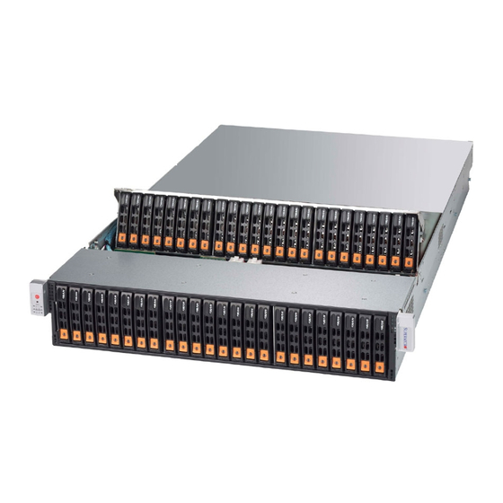
- Page 1 ® UpER toRAgE ERvER 2028R-NR48N USER’S MANUAL Revision 1.0...
- Page 2 This product, including software and documentation, is the property of Supermicro and/or its licensors, and is supplied only under a license. Any use or reproduction of this product is not allowed, except as expressly permitted by the terms of said license.
-
Page 3: About This Manual
(www.supermicro.com). This manual may be periodically updated without notice. Please check the Supermicro Web site for possible updates to the manual revision level. Warnings Special attention should be given to the following symbols used in this manual. -
Page 4: Table Of Contents
SuperStorage Server 2028R-NR48N Contents Chapter 1 Introduction Overview ......................1-1 Motherboard Features ..................1-2 Processors ...................... 1-2 Memory ......................1-2 NVMe Ports ....................1-2 Serial ATA ...................... 1-2 PCI Expansion Slots ..................1-2 Rear I/O Ports ....................1-2 SIOM Network Slot ..................1-3 Chassis Features .................. - Page 5 Preface Control Panel Buttons ..................3-2 Power ......................3-2 Reset ....................... 3-2 Control Panel LEDs ..................3-2 Overheating ..................... 3-4 Drive Carrier LEDs ..................3-4 Power Supply LEDs ..................3-5 Chapter 4 Standardized Warning Statements for AC Systems About Standardized Warning Statements ............4-1 Warning Definition ...................
- Page 6 SuperStorage Server 2028R-NR48N Control Panel Connector ................5-14 Other Connectors ..................5-16 Jumper Settings .................... 5-20 Onboard Indicators ..................5-22 Drive Ports ....................5-24 SATA ......................5-24 NVMe ......................5-24 5-10 Installing Software ..................5-25 SuperDoctor 5 ..................... 5-26 ®...
- Page 7 Preface Appendix A BIOS Error Beep Codes Appendix B UEFI BIOS Recovery Instructions Appendix C System Specifications...
- Page 8 SuperStorage Server 2028R-NR48N Notes viii...
-
Page 9: Chapter 1 Introduction
MySQL or Casandra, virtual storage environments, single instance storage and data deduplication. Refer to the Supermicro web site for information on operating systems that have been certified for use with the system (www.supermicro.com). In addition to the above components, the server includes: •... -
Page 10: Motherboard Features
SuperStorage Server 2028R-NR48N Motherboard Features The SuperStorage server 2028R-NR48N is built around the X10DSC+, a dual processor motherboard based on the Intel C612 chipset. Below are the main features. (See Figure 1-1 for a block diagram of the chipset.) Processors The motherboard supports single or dual Intel E5-2600 v3/v4 Series processors in socket R3 (LGA 2011). -
Page 11: Siom Network Slot
Chapter 1: Introduction SIOM Network Slot The motherboard provides a PCI-E x16 slot for a Super I/O module (SIOM) networking card. Several SIOM configurations are available. X10DSC+ Block Diagram NCSI DDR3 DDR3 NCSI AST2400 IPMI LAN RTL8211E 32MB BMC UART COM1 SPI Flash SPI USB... -
Page 12: Chassis Features
SuperStorage Server 2028R-NR48N Chassis Features The 2028R-NR48N is built upon the SC226STS-R1K62P2 chassis. System Power The system features dual redundant 1600 W power supplies consisting of two hot-plug power modules. They have 80 Plus certification at Titanium Level (96%) high-efficiency. The system will continue to operate if one module fails or is replaced. Drives The chassis supports forty-eight hot-swap 2.5"... -
Page 13: Contacting Supermicro
Super Micro Computer, Inc. 980 Rock Ave. San Jose, CA 95131 U.S.A. Tel: +1 (408) 503-8000 Fax: +1 (408) 503-8008 Email: marketing@supermicro.com (General Information) support@supermicro.com (Technical Support) Web Site: www.supermicro.com Europe Address: Super Micro Computer B.V. Het Sterrenbeeld 28, 5215 ML... - Page 14 SuperStorage Server 2028R-NR48N Notes...
-
Page 15: Chapter 2 Rack Installation
Chapter 2 Rack Installation This chapter provides instructions for preparing and mounting your chassis in a rack. Unpacking the System You should inspect the box the chassis was shipped in and note if it was damaged in any way. If the chassis itself shows damage, file a damage claim with the carrier who delivered it. -
Page 16: Warnings And Precautions
SuperStorage Server 2028R-NR48N Warnings and Precautions Rack Precautions • Ensure that the leveling jacks on the bottom of the rack are fully extended to the floor with the full weight of the rack resting on them. • In single rack installations, stabilizers should be attached to the rack. •... -
Page 17: Rack Mounting Considerations
Rack Mounting Considerations Ambient Operating Temperature If installed in a closed or multi-unit rack assembly, the ambient operating temperature of the rack environment may be greater than the ambient temperature of the room. Therefore, consideration should be given to installing the equipment in an environment compatible with the manufacturer’s maximum rated ambient temperature (TMRA). -
Page 18: Rack Mounting Instructions
SuperStorage Server 2028R-NR48N Rack Mounting Instructions This section provides information on installing the chassis into a rack unit with the rails provided. There are a variety of rack units on the market, which may mean that the assembly procedure will differ slightly from the instructions provided. You should also refer to the installation instructions that came with the rack unit you are using. -
Page 19: Releasing The Inner Rail
Releasing the Inner Rail It is necessary to release the inner rail from the middle and outer rails before installing the inner rail on the chassis. Releasing the Inner Rail from the Middle and Outer Rails 1. Lift the front latch on the inner rail and pull the inner rail out of the middle rail, and the middle rail out of the outer rail until the rails are fully extended. -
Page 20: Installing The Inner Rails On The Chassis
SuperStorage Server 2028R-NR48N Installing The Inner Rails on the Chassis Installing the Inner Rails 1. Confirm that the left and right inner rails have been correctly identified. 2. Place the inner rail firmly against the side of the chassis, aligning the pins on the side of the chassis with the slotted thru holes in the inner rail. -
Page 21: Installing The Outer Rails On The Rack
Installing the Outer Rails on the Rack Installing the Outer Rails 1. Confirm that the left and right outer rails have been correctly identified. 2. Release the small locking lever on the inside of the middle rail and push the middle rail back into the outer rail. -
Page 22: Installing Into The Rack
SuperStorage Server 2028R-NR48N Installing into the Rack After the rails are installed on the chassis and on the rack, the server can be installed in the rack. It is heavy and requires two to three people to lift. Installing the Chassis into a Rack 1. -
Page 23: Removing The Chassis From The Rack
Removing the Chassis From the Rack Caution: The server is heavy and requires two to three people to lift it out. Removing the Chassis 1. Lift the right and left front latches which are just below the LED control panels on the front edges of the chassis. -
Page 24: Removing The Outer Rails From The Rack
Note: A small number of customers may have received a different outer rail than the one pictured. This rail features side release latch on the front of the outer rail., which opens inward to release the outer rail from the rack. Contact Supermicro Technical Support department if you need additional assistance. -
Page 25: Installing The Cable Management Arm
Installing the Cable Management Arm The SC226S chassis supports a cable management arm (CMA) that allows servicing while the server is running. The CMA keeps the rear cables organized and clear of the rail mechanisms when the system is extended out the front of the rack. The kit includes six fabric Velcro cable ties. - Page 26 SuperStorage Server 2028R-NR48N Figure 2-10. Intalling the Connectors 3 and 4 3. Slide CMA connector #3 forward onto the two posts on the rear of the left middle rail. It snaps into place. 4. For CMA connector #4, align the metal tabs with the slots on the rear of the left outer rail and push it forward.
- Page 27 If at some time you must remove the cable management arm, follow this procedure. Removing the Cable Management Arm 1. Remove cables from the CMA, releasing the Velcro straps and the red plastic caps. 2. For CMA connector #4, pull the metal release tab toward the center of the rack and slide the connector toward the rear to release it.
- Page 28 SuperStorage Server 2028R-NR48N Notes 2-14...
-
Page 29: Chapter 3 System Interface
Chapter 3: System Interface Chapter 3 System Interface Overview The server includes a control panel on the front that house power buttons and status monitoring lights. The externally accessible hard drives display status lights. The power supply displays status lights visible from the back of the chassis. Figure 3-1. -
Page 30: Control Panel Buttons
SuperStorage Server 2028R-NR48N Control Panel Buttons The chassis control panel includes two push-buttons that controls power. Power The main power switch applies or removes primary power from the power supply to the computing nodes but maintains standby power. To perform most maintenance tasks, unplug the system to remove all power. -
Page 31: Power Fail
Chapter 3: System Interface NIC2 Indicates network activity on GLAN2 when flashing. NIC1 Indicates network activity on GLAN1 when flashing. Power Fail Indicates a power supply module has failed. Information LED Alerts operator to several states, as noted in the table below. Information LED Status Description... -
Page 32: Overheating
SuperStorage Server 2028R-NR48N Overheating A sensor on the backplane will issue a warning at 45°C. Overheating is critical at 49°C. There are several possible responses if the system overheats. If the server overheats: 1. Use the LEDs to determine the nature of the overheating condition. 2. -
Page 33: Power Supply Leds
Chapter 3: System Interface Power Supply LEDs On the rear of the power supply module, an LED displays the status. • Solid Green: When illuminated, indicates that the power supply is on. • Solid Amber: When illuminated, indicates the power supply is plugged in and turned off, or the system is off but in an abnormal state. - Page 34 SuperStorage Server 2028R-NR48N Notes...
-
Page 35: Chapter 4 Standardized Warning Statements For Ac Systems
Only certified technicians should attempt to install or configure components. Read this chapter in its entirety before installing or configuring components in the Supermicro chassis. Some warnings may not apply for your system. These warnings may also be found on our web site at www.supermicro.com/about/ policies/safety_information.cfm. - Page 36 SuperStorage Server 2028R-NR48N Warnung WICHTIGE SICHERHEITSHINWEISE Dieses Warnsymbol bedeutet Gefahr. Sie befinden sich in einer Situation, die zu Verletzungen führen kann. Machen Sie sich vor der Arbeit mit Geräten mit den Gefahren elektrischer Schaltungen und den üblichen Verfahren zur Vorbeugung vor Unfällen vertraut.
- Page 37 Chapter 4: Warning Statements for AC Systems جسذٌة اصابة ًتتسبب ف حالة ٌوكي أى ًاًك ف خطز ًٌٌع هذا الزهز !تحذٌز الذوائز بالوخاطز الٌاجوة عي ي على علن ، ك هعذات تعول على أي قبل أى الكهزبائٍة حىادث أي وقىع وٌع...
-
Page 38: Installation Instructions
SuperStorage Server 2028R-NR48N Installation Instructions Warning! Read the installation instructions before connecting the system to the power source. 設置手順書 システムを電源に接続する前に、 設置手順書をお読み下さい。 警告 将此系统连接电源前,请先阅读安装说明。 警告 將系統與電源連接前,請先閱讀安裝說明。 Warnung Vor dem Anschließen des Systems an die Stromquelle die Installationsanweisungen lesen. ¡Advertencia! Lea las instrucciones de instalación antes de conectar el sistema a la red de alimentación. -
Page 39: Circuit Breaker
Chapter 4: Warning Statements for AC Systems Circuit Breaker Warning! This product relies on the building's installation for short-circuit (overcurrent) protection. Ensure that the protective device is rated not greater than: 250 V, 20 A. サーキッ ト ・ ブレーカー この製品は、 短絡 (過電流) 保護装置がある建物での設置を前提としています。 保護装置の定格が250 V、... -
Page 40: Power Disconnection Warning
SuperStorage Server 2028R-NR48N 경고! 이 제품은 전원의 단락(과전류)방지에 대해서 전적으로 건물의 관련 설비에 의존합니다. 보호장치의 정격이 반드시 250V(볼트), 20A(암페어)를 초과하지 않도록 해야 합니다. Waarschuwing Dit product is afhankelijk van de kortsluitbeveiliging (overspanning) van uw electrische installatie. Controleer of het beveiligde aparaat niet groter gedimensioneerd is dan 220V, 20A. - Page 41 Chapter 4: Warning Statements for AC Systems ¡Advertencia! El sistema debe ser disconnected de todas las fuentes de energía y del cable eléctrico quitado de los módulos de fuente de alimentación antes de tener acceso el interior del chasis para instalar o para quitar componentes de sistema. Attention Le système doit être débranché...
-
Page 42: Equipment Installation
SuperStorage Server 2028R-NR48N Equipment Installation Warning! Only trained and qualified personnel should be allowed to install, replace, or service this equipment. 機器の設置 トレーニングを受け認定された人だけがこの装置の設置、 交換、 またはサービスを許可 されています。 警告 只有经过培训且具有资格的人员才能进行此设备的安装、更换和维修。 警告 只有經過受訓且具資格人員才可安裝、更換與維修此設備。 Warnung Das Installieren, Ersetzen oder Bedienen dieser Ausrüstung sollte nur geschultem, qualifiziertem Personal gestattet werden. -
Page 43: Restricted Area
Chapter 4: Warning Statements for AC Systems Waarschuwing Deze apparatuur mag alleen worden geïnstalleerd, vervangen of hersteld door geschoold en gekwalificeerd personeel. Restricted Area Warning! This unit is intended for installation in restricted access areas. A restricted access area can be accessed only through the use of a special tool, lock and key, or other means of security. -
Page 44: Battery Handling
SuperStorage Server 2028R-NR48N אזור עם גישה מוגבלת !אזהרה יש להתקין את היחידה באזורים שיש בהם הגבלת גישה. הגישה ניתנת בעזרת .)'כלי אבטחה בלבד (מפתח, מנעול וכד محظورة مناطق ٍنتركُبها ف هذه انىحذة تخصيص تم ،أداة خاصت من خالل استخذاو فقط... - Page 45 Chapter 4: Warning Statements for AC Systems Warnung Bei Einsetzen einer falschen Batterie besteht Explosionsgefahr. Ersetzen Sie die Batterie nur durch den gleichen oder vom Hersteller empfohlenen Batterietyp. Entsorgen Sie die benutzten Batterien nach den Anweisungen des Herstellers. Attention Danger d'explosion si la pile n'est pas remplacée correctement. Ne la remplacer que par une pile de type semblable ou équivalent, recommandée par le fabricant.
-
Page 46: Redundant Power Supplies (If Applicable To Your System)
SuperStorage Server 2028R-NR48N Redundant Power Supplies (if applicable to your system) Warning! This unit might have more than one power supply connection. All connections must be removed to de-energize the unit. 冗長電源装置 このユニッ トは複数の電源装置が接続されている場合があります。 ユニッ トの電源を切るためには、 すべての接続を取り外さなければなりません。 警告 此部件连接的电源可能不止一个,必须将所有电源断开才能停止给该部件供电。 警告... -
Page 47: Backplane Voltage (If Applicable To Your System)
Chapter 4: Warning Statements for AC Systems امداد الطاقة بوحدات عدة اتصاالت جهاز ال يكون لهذا قد الكهرباء عن وحدة ال لعسل كافة االتصاالت يجب إزالة 경고! 이 장치에는 한 개 이상의 전원 공급 단자가 연결되어 있을 수 있습니다. 이 장치에... -
Page 48: Comply With Local And National Electrical Codes
SuperStorage Server 2028R-NR48N מתח בפנל האחורי !הרה אז קיימת סכנת מתח בפנל האחורי בזמן תפעול המערכת. יש להיזהר במהלך .העבודה اللىحة أوالطاقة المىجىدة على التيار الكهزبائي مه خطز هناك هذا الجهاس خدمة كه حذرا عند يعمل النظام عندما يكىن 경고! 시스템이... -
Page 49: Product Disposal
Chapter 4: Warning Statements for AC Systems Attention L'équipement doit être installé conformément aux normes électriques nationales et locales. תיאום חוקי החשמל הארצי !אזהרה הציוד חייבת להיות תואמת לחוקי החשמל המקומיים והארציים התקנת المتعلقة المحلية والىطىية قىاويه يجب أن يمتثل لل الكهربائية... -
Page 50: Hot Swap Fan Warning (If Applicable To Your System)
SuperStorage Server 2028R-NR48N ¡Advertencia! Al deshacerse por completo de este producto debe seguir todas las leyes y reglamentos nacionales. Attention La mise au rebut ou le recyclage de ce produit sont généralement soumis à des lois et/ou directives de respect de l'environnement. Renseignez-vous auprès de l'organisme compétent. - Page 51 Chapter 4: Warning Statements for AC Systems 警告 當您從機架移除風扇裝置,風扇可能仍在轉動。小心不要將手指、螺絲起子和其他 物品太靠近風扇。 Warnung Die Lüfter drehen sich u. U. noch, wenn die Lüfterbaugruppe aus dem Chassis genommen wird. Halten Sie Finger, Schraubendreher und andere Gegenstände von den Öffnungen des Lüftergehäuses entfernt. ¡Advertencia! Los ventiladores podran dar vuelta cuando usted quite ell montaje del ventilador del chasis.
-
Page 52: Power Cable And Ac Adapter
Electrical Appliance and Material Safety Law prohibits the use of UL or CSA -certified cables (that have UL/CSA shown on the code) for any other electrical devices than products designated by Supermicro only. 電源コードとACアダプター 製品を設置する場合、 提供または指定された接続ケーブル、 電源コードとACアダプター... - Page 53 Appareils électroménagers et de loi sur la sécurité Matériel interdit l'utilisation de UL ou CSA câbles certifiés qui ont UL ou CSA indiqué sur le code pour tous les autres appareils électriques que les produits désignés par Supermicro seulement.
- Page 54 SuperStorage Server 2028R-NR48N Notes 4-20...
-
Page 55: Chapter 5 Advanced Motherboard Setup
Chapter 5: Advanced Serverboard Setup Chapter 5 Advanced Motherboard Setup This chapter provides detailed information on the X10DSC+ motherboard. All motherboard jumpers and connections are described. A layout and quick reference chart are also included in this chapter for your reference. Remember to completely close the chassis when you have finished working with the motherboard to better cool and protect the system. -
Page 56: Cable And Device Connectiions
SuperStorage Server 2028R-NR48N Cable and Device Connectiions All data and power connections between the motherboard to the system (including the power supplies and the hard drives) are provided through the midplane. Most of these connections are made automatically when the system is assembled. "Right" and "left"... -
Page 57: Processor And Heatsink Installation
• Install the processor into the CPU socket before installing the heatsink. • Refer to the Supermicro website for updates on CPU support. Installing a CPU 1. There are two levers on the LGA 2011 socket. First press and release the load lever labeled "Open 1st". - Page 58 SuperStorage Server 2028R-NR48N 3. W ith the sec ond lever f ully Open the load plate. retracted, gently push down on the "Open 1st" lever to loosen the load plate. Lift the load plate with your fingers to open it completely. 4.
- Page 59 Chapter 5: Advanced Serverboard Setup Gently close the load plate. 7. With the "Close 1st" lever fully retracted, gently close the load plate. Push down and lock the lever labeled "Close 1st". 8. Make sure the locking mechanism on the "Close 1st" lever catches the lip of the load plate.
-
Page 60: Installing A Cpu Heatsink
SuperStorage Server 2028R-NR48N Installing a CPU Heatsink 1. Remove power from the system and unplug the AC power cord from the power supply. 2. Place the heatsink on top of the CPU so that the four mounting holes are aligned with those on the (preinstalled) heatsink retention mechanism. -
Page 61: Installing Memory
Chapter 5: Advanced Serverboard Setup Installing Memory Memory Support The X10DSC+ supports Load Reduced (LRDIMM) or Registered (RDIMM) ECC DDR4-2400/2133/1866/1600 memory. For best performance, install pairs of memory modules of the same type and speed. All channels will run at the fastest common frequency. - Page 62 SuperStorage Server 2028R-NR48N Processor & Memory Module Population Configuration Follow the tables below for correct memory installation. Processors and their Corresponding Memory Modules CPU# Corresponding DIMM Modules CPU 1 CPU2 Processor and Memory Module Population for Optimal Performance Number of CPU and Memory Population Configuration Table CPUs+DIMMs 1 CPU &...
- Page 63 Chapter 5: Advanced Serverboard Setup Populating RDIMM/LRDIMM DDR4 Memory Modules Speed (MT/s); Voltage (V); Slots per Channel (SPC) and DIMMs per Channel (DPC) Ranks 3 Slots per Channel DIMM Capacity DIMM (GB) 1 DPC 2 DPC 3 DPC Type Data E5-2600 V3 E5-2600 V4 E5-2600 V3...
-
Page 64: Motherboard Details
SuperStorage Server 2028R-NR48N Motherboard Details COM1 USB0/1(3.0) LED1 IPMI_LAN CPU2_MEMORY_LED CPU1_MEMORY_LED BMC_HB_LED1 CPU1 SIOM PCI-E 3.0 CPU2 HDD_LED1 LED2 CPU1 JSD2 JSD1 JBAT1 BIOS Battery S-SGPIO1 X10DSC+ REV:1.01 JITP1 JPW2 BIOS JPW3 IPMI CODE CPU-XDP LICENSE JPW1 BAR CODE JTPM1 Figure 5-3. - Page 65 Chapter 5: Advanced Serverboard Setup Connectors Description COM1 Rear COM Port FAN1-FAN5 System Fan Headers (Fan 1-Fan 5) Front Control Panel Header C_EXP1/2 System Management Bus (SMBus) I C for SAS3 Backplane C_FP1 System Management Bus (SMBus) I C for LCD Devices JIPMB1 4-pin external BMC I C Header (for an IPMI card)
- Page 66 SuperStorage Server 2028R-NR48N Description State Status CPU1 Memory Fail LED_A1-A3 LED for DIMMs Memory Failure A1-A3 CPU1 Memory Fail LED_B1-B3 LED for DIMMs Memory Failure B1-B3 CPU1 Memory Fail LED_C1-C3 LED for DIMMs Memory Failure C1-C3 CPU1 Memory Fail LED_D1-D3 LED for DIMMs Memory Failure D1-D3...
-
Page 67: Connector Definitions
Chapter 5: Advanced Serverboard Setup Connector Definitions Power Connectors ATX Power 24-pin Connector Pin Definitions Pin# Definition Pin # Definition Power Connectors +3.3V +3.3V -12V +3.3V A 24-pin main power supply connector (JPW1) and two 8-pin CPU power PS_ON connectors (JPW2/JPW3) must be connected to the power supply to provide adequate power to the system. -
Page 68: Control Panel Connector
SuperStorage Server 2028R-NR48N Control Panel Connector Power Button Ground Ground Reset Button Power Fail LED 3.3V OH/Fan Fail/ UID LED PWR Fail LED) NIC2 Activity LED NIC2 Link LED NIC1 Activity LED NIC1 Link LED UID Switch HDD LED FP PWRLED 3.3 V Ground Figure 5-4. - Page 69 Chapter 5: Advanced Serverboard Setup Power Fail LED PWR Fail LED Pin Definitions (JF1) The Power Fail LED connection Pin# Definition is located on pins 5 and 6 of JF1. 3.3V Refer to the table on the right for pin PWR Supply Fail definitions.
-
Page 70: Other Connectors
SuperStorage Server 2028R-NR48N Power On LED Power LED The Power On LED connector is Pin Definitions (JF1) located on pins 15 and 16 of JF1. This connection is used to provide LED Pin# Definition indication of power being supplied to 3.3V the system. - Page 71 Chapter 5: Advanced Serverboard Setup Dedicated IPMI LAN Port A dedicated IPMI LAN port is located above the rear USB 0/1 ports. Connect an RJ45 cable here for IPMI LAN support. Please refer to the LED Indicator section for LAN LED information. Serial Ports One serial port (COM1) is located at the rear of the server.
- Page 72 SuperStorage Server 2028R-NR48N PWR SMBus Header Pin Definitions Power Supply SMBus I C Header Pin# Definition The power System Management Bus Clock header at JPI C1 is used to monitor Data the status of the power supply, fan and PWR Fail system temperature.
- Page 73 Note: UID can also be triggered via IPMI. For more information on IPMI, please refer to the IPMI User's Guide posted on our website at http://www.supermicro.com. TPM/Port 80 Header Pin Definitions...
-
Page 74: Jumper Settings
SuperStorage Server 2028R-NR48N Jumper Settings Explanation of Jumpers To modify the operation of the motherboard, jumpers can be used Connector to choose between optional settings. Pins Jumpers create shorts between two pins to change the function of the connector. Pin 1 is identified with Jumper a square solder pad on the printed circuit board. - Page 75 Chapter 5: Advanced Serverboard Setup Watch Dog Enable/Disable Jumper JWD controls the Watch Dog function. Watch Dog is a system monitor that can reboot the system when a software application hangs. Jumping pins 1-2 will cause WD to Watch Dog Jumper Settings reset the system if an application Jumper Setting...
-
Page 76: Onboard Indicators
SuperStorage Server 2028R-NR48N Onboard Indicators Dedicated IPMI LAN LEDs IPMI LAN Link LED (Left) & Activity LED (Right) A dedicated IPMI LAN is also located Color/State Definition on the I/O back panel. The amber LED Link (Left) Green: Solid 100 Mbps on the right indicates activity, while the Amber: Solid 1 Gbps... - Page 77 Chapter 5: Advanced Serverboard Setup Onboard Memory_Fault LED Memory-Fault LED Indicators & Indicators Corresponding DIMM LED Indicator Corresponding DIMMs The memory-fault LED indicators LED_A1-A3 P1DIMM_A1-A3 are located at LED_A1 - LED_H3 LED_B1-B3 P1DIMM_B1-B3 on the motherboard. Each memory LED_C1-C3 P1DIMM_C1-C3 LED indicates the status of the DIMM LED_D1-D3 P1DIMM_D1-D3...
-
Page 78: Drive Ports
SATADOMs that require an external power supply. Note2: For more information on SATA HostRAID configuration, please refer to the Intel SATA HostRAID User's Guide posted on our website at http://www.supermicro. com. NVMe The motherboard features four NVMExpress ports (#0-#3) in the form PCI-E 3.0 x4 slots. -
Page 79: 5-10 Installing Software
Chapter 5: Advanced Serverboard Setup 5-10 Installing Software The Supermicro FTP site contains drivers and utilities for your system at ftp://ftp. supermicro.com. Some of these must be installed, such as the chipset driver. After accessing the FTP site, go into the CDR_Images directory and locate the ISO file for your motherboard. -
Page 80: Superdoctor ® 5
2028R-NR48N SuperDoctor ® The Supermicro SuperDoctor 5 is a program that functions in a command-line or web-based interface in Windows and Linux operating systems. The program monitors system health information such as CPU temperature, system voltages, system power consumption, fan speed, and provides alerts via email or Simple Network Management Protocol (SNMP). -
Page 81: 5-11 Onboard Battery
Chapter 5: Advanced Serverboard Setup 5-11 Onboard Battery Please handle used batteries carefully. Do not damage the battery in any way; a damaged battery may release hazardous materials into the environment. Do not discard a used battery in the garbage or a public landfill. Please comply with the regulations set up by your local hazardous waste management agency to dispose of your used battery properly. - Page 82 SuperStorage Server 2028R-NR48N Notes 5-28...
-
Page 83: Chapter 6 Chassis Setup And Maintenance
Chapter 6: Chassis Setup and Maintenance Chapter 6 Chassis Setup and Maintenance Overview This chapter covers the steps required to install components and perform maintenance on the chassis. The only tool required is a Phillips screwdriver. Review the warnings and precautions listed in the manual before setting up or servicing this chassis. -
Page 84: Removing Power From The System
SuperStorage Server 2028R-NR48N Removing Power from the System Before performing some setup or maintenance tasks, use the following procedure to ensure that power has been removed from the system. 1. Use the operating system to power down the node, following the on-screen prompts. -
Page 85: Removing The Top Covers
Chapter 6: Chassis Setup and Maintenance Removing the Top Covers Mid-chassis Cover The mid-chassis cover can be removed to access the mid-chassis drives or fans while the server continues to operate. Remove Screw Push Button Remove Screw Push Button Figure 6-3. Removing the Mid-chassis Cover Removing the Mid-chassis Cover Remove the two screws securing each side of the cover, push in the tabs, then lift the cover. -
Page 86: Rear Cover
SuperStorage Server 2028R-NR48N Rear Cover Remove Screw Figure 6-4. Removing the Rear Cover Removing the Rear Cover Remove the thumbscrew at the rear of the chassis, then slide the cover to the rear and off. -
Page 87: Storage Drives
RAID. Threre are also two hot-swap hard drive bays in the rear. Note: Enterprise level SSDs and hard disk drives are recommended for use in Supermicro servers. For information on recommended drives, visit the Supermicro website. Drive Connections NVMe drive slot numbers 0-23 are attached through the front backplane and from 16 PCI-E 3.0 lanes from CPU1. -
Page 88: Drive Carriers
SuperStorage Server 2028R-NR48N Drive Carriers The drives are mounted in drive carriers to simplify their installation and removal from the chassis. These carriers also help promote proper airflow through the drive bays. Each drive carrier has two LED indicators. These are described in Chapter 3. Removing Drive Carriers from the Chassis 1. -
Page 89: Installing A Solid State Drive (Ssd)
Chapter 6: Chassis Setup and Maintenance Installing a Solid State Drive (SSD) 1. Remove the screws securing the dummy drive to the carrier. 2. Remove the dummy drive from the carrier. Figure 6-7. Removing a Dummy Drive from the Drive Carrier 3. -
Page 90: Installing Rear Hard Drives
SuperStorage Server 2028R-NR48N Caution: Except for short periods of time, such as swapping hard drives, do not operate the server with the hard drive bays empty. Installing Rear Hard Drives The two drives in the rear of the chassis are installed in the same way as the main storage drives (SSDs). -
Page 91: Installing The Expansion Cards
Chapter 6: Chassis Setup and Maintenance Installing the Expansion Cards The system provides three PCI slots for low profile, full-length expansion cards. Installing an Expansion Cards 1. Power down the system as described in Section 6-2. Remove both covers as described in Section 6-3. - Page 92 SuperStorage Server 2028R-NR48N Installing a SIOM Card 1. Power down the system as described in Section 6-2. 2. Remove the small section of the chassis rear to allow access to the motherboard SIOM slot. Unscrew the single retaining screw to remove the cover. Cover Retaining Screw Figure 6-11.
-
Page 93: System Fans
Chapter 6: Chassis Setup and Maintenance System Fans Five heavy-duty fans provide cooling for the system. They can be replaced without powering down the system. Replacing a System Fan 1. If necessary, open the chassis while the power is running to determine which fan requires changing. - Page 94 SuperStorage Server 2028R-NR48N Figure 6-14. Placing the System Fan 6-12...
-
Page 95: Installing The Air Shrouds
Chapter 6: Chassis Setup and Maintenance Installing the Air Shrouds Air shrouds concentrate airflow to maximize fan efficiency. They do not require screws for installation. Installing the Air Shroud 1. Power down the system as described in Section 5-2. Remove the covers as described in Section 5-3. -
Page 96: Power Supply
The chassis features redundant power supplies. The power modules can be changed without powering down the system. New units can be ordered directly from Supermicro or authorized distributors. These power supplies are auto-switching capable. This feature enables them to automatically sense the input voltage and operate at a 100-120v or 180-240v. -
Page 97: Chapter 7 Bios
AMI BIOS setup utility. This setup utility can be accessed by pressing <Delete> at the appropriate time during system boot. Note: For AMI UEFI BIOS Recovery, please refer to the UEFI BIOS Recovery User Guide posted @ http://www.supermicro.com/support/manuals/. -
Page 98: Main Setup
SuperStorage Server 2028R-NR48N Starting the Setup Utility Normally, the only visible Power-On Self-Test (POST) routine is the memory test. As the memory is being tested, press the <Delete> key to enter the main menu of the AMI BIOS setup utility. From the main menu, you can access the other setup screens. - Page 99 Chapter 7: AMI BIOS Supermicro X10DSC+ BIOS Version This item displays the version of the BIOS ROM used in this system. Build Date This item displays the date that the BIOS setup utility was built. CPLD (Complex Programmable Logic Device) Version: This item displays the CPLD version used in the system.
-
Page 100: Advanced Setup Configurations
SuperStorage Server 2028R-NR48N Advanced Setup Configurations Use the arrow keys to select Advanced Setup and press <Enter> to access the following submenu items. If the NVMe SSD firmware is supported, this screen will pull status information from the SSDs installed in the drive bays that support Option ROM (see Page 7-21 for more details). -
Page 101: Power Configuration
Chapter 7: AMI BIOS Bootup Num-Lock State Use this item to set the Power-on state for the Numlock key. The options are Off and On. Wait For 'F1' If Error Select Enabled to force the system to wait until the <F1> key is pressed when an error occurs. -
Page 102: Cpu Configuration
SuperStorage Server 2028R-NR48N Restore on AC Power Loss Use this feature to set the power state after a power outage. Select Power Off for the system power to remain off after a power loss. Select Power On for the system power to be turned on after a power loss. - Page 103 Chapter 7: AMI BIOS Execute Disable Bit (Available if supported by the OS & the CPU) Select Enable for Execute Disable Bit Technology support, which will allow the processor to designate areas in the system memory where an application code can execute and where it cannot, thus preventing a worm or a virus from flooding illegal codes to overwhelm the processor to damage the system during an attack.
-
Page 104: Advanced Power Management Configuration
SuperStorage Server 2028R-NR48N X2 APIC (Advanced Programmable Interrupt Controller) Based on Intel's Hyper-Threading architecture, each logical processor (thread) is assigned 256 APIC IDs (APIDs) in 8-bit bandwidth. When this feature is set to Enable, the APIC ID will expand(X2) from 8 bits to 16 bits to provide 512 APIDs to each thread to enhance CPU performance. - Page 105 Chapter 7: AMI BIOS use more power to boost system performance. The options are Performance, Balanced Performance, Balanced Power, and Power. Energy Efficiency Turbo (Available when Power Technology is set to Custom or Energy Efficient) Select Enable for the system to operate at turbo mode with reduced power consumption so that your machine can achieve maximum system performance with the maximum power efficiency possible.
-
Page 106: Chipset Configuration
SuperStorage Server 2028R-NR48N CPU C3 Report Select Enable to allow the BIOS to report the CPU C3 state (ACPI C2) to the operating system. During the CPU C3 state, the CPU clock generator is turned off. The options are Enable and Disable. CPU C6 Report (Available when Power Technology is set to Custom) Select Enable to allow the BIOS to report the CPU C6 state (ACPI C3) to the operating system. - Page 107 Chapter 7: AMI BIOS IIO1 Configuration IOU2 (IIO1 PCIe Port 1) This item configures the PCI-E port Bifuraction setting for a PCI-E port specified by the user. The options are x4x4, x8, and Auto. IIO1 Port 1A Link Speed This item configures the link speed of a PCI-E port specified by the user. The options are Gen 1 (Generation 1) (2.5 GT/s), Gen 2 (Generation 2) (5 GT/s), and Gen 3 (Generation 3) (8 GT/s).
-
Page 108: Ioat Configuration
SuperStorage Server 2028R-NR48N IIO2 Port 1A Link Speed This item configures the link speed of a PCI-E port specified by the user. The options are Gen 1 (Generation 1) (2.5 GT/s), Gen 2 (Generation 2) (5 GT/s), and Gen 3 (Generation 3) (8 GT/s). IOU0 (IIO2 PCIe Port 2) This item configures the PCI-E port Bifuraction setting for a PCI-E port specified by the user. - Page 109 Chapter 7: AMI BIOS Intel VT for Directed I/O (VT-d) Intel VT for Directed I/O (VT-d) Select Enable to use the Intel Virtualization Technology for Direct I/O VT-d support by reporting the I/O device assignments to the VMM (Virtual Machine Monitor) through the DMAR ACPI tables.
-
Page 110: Memory Configuration
SuperStorage Server 2028R-NR48N Early Snoop (Available when the OS and the CPU support this feature) Select Enable for Early Snoop support to enhance system performance. The options are Enable, Disable, and Auto. Home Dir Snoop with IVT-Style OSB (Available when the OS and the CPU support this feature) Select Enable for Home-Direct Snoop with IVT-Style_OSB support to enhance system performance. -
Page 111: Dimm Information
Chapter 7: AMI BIOS A7 Mode Select Enable to support A7 (Addressing) mode to improve memory performance. The options are Enable and Disable. DIMM Information This item displays the status of a DIMM module as detected by the AMI BIOS. •... -
Page 112: South Bridge Configuration
SuperStorage Server 2028R-NR48N Demand Scrub Demand Scrubbing is a process that allows the CPU to correct correctable memory errors found on a memory module. When the CPU or I/O issues a demand-read command, and the read data from memory turns out to be a correctable error, the error is corrected and sent to the requestor (the original source). - Page 113 Chapter 7: AMI BIOS Port 60/64 Emulation Select Enabled to support I/O port 60h/64h emulation, which will provide complete legacy USB keyboard support for the operating systems that do not support legacy USB devices. The options are Disabled and Enabled. USB 3.0 Support Select Enabled for USB 3.0 support.
- Page 114 SuperStorage Server 2028R-NR48N sSATA AHCI ALPM Select Enabled for the sSATA controller to automatically generate link requests in partial or slumber mode when there is no commands for the system to execute. The options are Disabled, and Enabled. sSATA Port 0~ Port 3 This item displays the information detected on the installed on the sSATA port.
- Page 115 Chapter 7: AMI BIOS *If the item above "Configure sSATA as" is set to RAID, the following items will display: sSATA AHCI ALPM Select Enabled for the sSATA controller to automatically generate link requests in partial or slumber mode when there is no commands for the system to execute. The options are Disabled, and Enabled.
- Page 116 SuperStorage Server 2028R-NR48N • ME Firmware Type • Recovery Firmware Version • ME Firmware Features • ME Firmware Status #1 • ME Firmware Status #2 • Current State • Error Code PCIe/PCI/PnP Configuration The following items will display: • PCI Bus Driver Version •...
- Page 117 Chapter 7: AMI BIOS on the system configuration. Select Disabled to disable ASPM support. The options are Disabled and Auto. Warning: Enabling ASPM support may cause some PCI-E devices to fail! MMIOHBase Use this item to select the I/O base memory size according to memory-address mapping for the PCH chip.
-
Page 118: Super Io Configuration
SuperStorage Server 2028R-NR48N Network Stack Select Enabled to enable PXE (Preboot Execution Environment) or UEFI (Unified Extensible Firmware Interface) for network stack support. The options are Enabled and Disabled. IPv4 PXE Support (Available when Network Stack is set to Enabled) Set this item to Enabled to activate IPv4 PXE Support. -
Page 119: Serial Port Console Redirection
Chapter 7: AMI BIOS Serial Port Console Redirection COM 1 COM 1 Console Redirection Select Enabled to enable COM Port 1 Console Redirection, which will allow a client machine to be connected to a host machine at a remote site for networking. The options are Disabled and Enabled. - Page 120 SuperStorage Server 2028R-NR48N Stop Bits A stop bit indicates the end of a serial data packet. Select 1 Stop Bit for standard serial data communication. Select 2 Stop Bits if slower devices are used. The options are 1 and 2. Flow Control Use this item to set the flow control for Console Redirection to prevent data loss caused by buffer overflow.
- Page 121 Chapter 7: AMI BIOS SOL Console Redirection Select Enabled to use the SOL port for Console Redirection. The options are Enabled and Disabled. *If the item above set to Enabled, the following items will become available for user's configuration: SOL Console Redirection Settings Use this feature to specify how the host computer will exchange data with the client computer, which is the remote computer used by the user.
- Page 122 SuperStorage Server 2028R-NR48N Stop Bits A stop bit indicates the end of a serial data packet. Select 1 Stop Bit for standard serial data communication. Select 2 Stop Bits if slower devices are used. The options are 1 and 2. Flow Control Use this feature to set the flow control for Console Redirection to prevent data loss caused by the overflow in the buffer.
- Page 123 Chapter 7: AMI BIOS Serial Port for Out-of-Band Management/Windows Emergency Management Services (EMS) The submenu allows the user to configure Console Redirection settings to support Out-of-Band Serial Port management. (EMS) Console Redirection Select Enabled to use a COM port selected by the user for EMS Console Redirection.
- Page 124 SuperStorage Server 2028R-NR48N The following settings will be displayed: Data Bits, Parity, Stop Bits Enabling TPM in the BIOS The steps below describe the proper procedure on how to enable the TPM in the BIOS. This process is necessary to activate support in the system before you can start using the TPM.
-
Page 125: Acpi Settings
EV DFX (Device Function On-Hide) support for the system to work properly. (EV DFX is under "IIO Configuration" in the "Chipset/North Bridge" submenu on Page 4-10). For more information on TPM, please refer to the TPM manual at http://www. supermicro.com/manuals/other/AOM-TPM-9655V_9655H.pdf ACPI Settings ... -
Page 126: Event Logs
SuperStorage Server 2028R-NR48N iSCSI Configuration This item displays iSCSI configuration information: iSCSI Initiator Name Use this item to enter the name of the iSCSI Initiator, which is a unique name used in the world. The name must in the IQN format. The following submenu will be available for configuration: ... -
Page 127: View Smbios Event Log
Chapter 7: AMI BIOS Enabling/Disabling Options SMBIOS Event Log Select Enabled to enable SMBIOS (System Management BIOS) Event Logging during system boot. The options are Enabled and Disabled. Runtime Error Logging Support Select Enable to support Runtime Error logging. The options are Enabled and Disabled. -
Page 128: Ipmi
SuperStorage Server 2028R-NR48N IPMI This submenu allows the user to configure IPMI settings. The following items will be displayed: • BMC (Baseboard Management Controller) Firmware Revision • IPMI Status System Event Log Enabling/Disabling Options SEL Components Select Enabled to enable all system event logging support at bootup. The options are Enabled and Disabled. -
Page 129: Bmc Network Configuration
Chapter 7: AMI BIOS Note: After making changes on a setting, be sure to reboot the system for the changes to take effect. BMC Network Configuration The following items will be displayed: • IPMI LAN Selection • IPMI Network Link Status Update IPMI LAN Configuration Select Yes for the system BIOS to automatically reset the following IPMI settings upon next system boot. -
Page 130: Security Settings
SuperStorage Server 2028R-NR48N Security Settings This submenu allows the user to configure the following security settings for the system. Password Check Select Setup for the system to prompt for a password upon entering the BIOS setup utility. Select Always for the system to prompt for a password at bootup and upon entering the BIOS Setup utility. -
Page 131: Key Management
Chapter 7: AMI BIOS Secure Boot Select Enable for secure boot support to ensure system security at bootup. The options are Enabled and Disabled. Secure Boot Mode This item allows the user to select the desired secure boot mode for the system. The options are Standard and Custom. - Page 132 SuperStorage Server 2028R-NR48N Authorized Signatures This feature allows the user to set and save authorized signatures and grant access to those whose names appear on the list. Forbidden Signatures This feature allows the user to set and save the forbidden signatures and deny the access to those whose names appear on the list.
-
Page 133: Boot Settings
Chapter 7: AMI BIOS Boot Settings This submenu allows the user to configure Boot settings for this system: Boot Configuration Setup Prompt Timeout Use this item to enter the number of seconds for the system to wait for the setup activation key before entering the Setup utility. - Page 134 SuperStorage Server 2028R-NR48N When the item above -"Boot Mode Select" is set to UEFI, the following items will be display for configuration: • Boot Option #1 - Boot Option #8 Add New Boot Option Use this item to select a new boot device to add to the boot priority list. Add New Boot Option Use this feature to select the target boot device to add to the boot priority list.
-
Page 135: Save & Exit
Chapter 7: AMI BIOS Save & Exit This submenu allows the user to configure the following Save & Exit settings: Discard Changes and Exit Select this item to exit from the BIOS setup without making any permanent changes to the system configuration, and reboot the computer. Save Changes and Reset When you have completed the system configuration changes, select this item to leave the BIOS setup utility and reboot the computer for the new system... - Page 136 SuperStorage Server 2028R-NR48N Save As User Defaults Select this item and press <Enter> to save the current BIOS settings as user's default settings for future use. Restore User Defaults Select this item and press <Enter> to retrieve the user-defined default settings that were previously saved to be used as current default settings.
-
Page 137: Bios Error Beep Codes
Appendix A: BIOS Error Beep Codes Appendix A BIOS Error Beep Codes During the POST (Power-On Self-Test) routines, which are performed at each system boot, errors may occur. Non-fatal errors are those which, in most cases, allow the system to continue to boot. - Page 138 SuperStorage Server 2028R-NR48N Notes...
- Page 139 Flashing the wrong BIOS can cause irreparable damage to the system. In no event shall Supermicro be liable for direct, indirect, special, incidental, or consequential damages arising from a BIOS update. If you need to update the BIOS, do not shut down or reset the system while the BIOS is updating to avoid possible boot failure.
- Page 140 Root "\" Directory of a USB device or a writeable CD/DVD. Note: If you cannot locate the "Super.ROM" file in your driver disk, visit our website at www.supermicro.com to download the BIOS image into a USB flash device and rename it "Super.ROM" for BIOS recovery use.
- Page 141 Appendix B: UEFI BIOS Recovery 4. After locating the new BIOS binary image, the system will enter the BIOS Recovery menu as shown below. Note: At this point, you may decide if you want to start with BIOS recovery. If you decide to proceed with BIOS recovery, follow the procedures below.
- Page 142 SuperStorage Server 2028R-NR48N 6. After the process of BIOS recovery is completed, press any key to reboot the system. 7. Using a different system, extract the BIOS package into a bootable USB flash drive. 8. When a DOS prompt appears, enter FLASH.BAT BIOSname.### at the prompt. Note: Do not interrupt this process until BIOS flashing is completed.
-
Page 143: System Specifications
Appendix C: System Specifications Appendix C System Specifications Processors Single or dual Intel E5-2600 v3/v4 Series processors in LGA2011 sockets Note: Please refer to our web site for a complete listing of supported processors. Chipset Intel C612 chipset BIOS 16 MB AMI SPI Flash EEPROM Memory Capacity Twenty-four DIMM slots that can support ECC LRDIMM (Load Reduced) or ECC Registered (RDIMM) DDR4-2400/2133/1866/1600 memory... -
Page 144: System Cooling
SuperStorage Server 2028R-NR48N Dimensions Width 17.2" (437mm), Height 3.5" (89mm), Depth 30.2" (767mm), with Cable Management Arm Installed 35.2" (895mm) Weight Gross Weight: 74.5 lbs. (33.8 kg.) Net Weight: 52 lbs. (23.6 kg.s) System Cooling Five 8cm hot-swap redundant PWM cooling fans; two air shrouds; two CPU heat... - Page 145 Appendix C: System Specifications Canada), CE Marking (Europe) California Best Management Practices Regulations for Perchlorate Materials: This Perchlorate warning applies only to products containing CR (Manganese Dioxide) Lithium coin cells. “Perchlorate Material-special handling may apply. See www.dtsc.ca.gov/hazardouswaste/perchlorate”...
- Page 146 SuperStorage Server 2028R-NR48N (continued from front) The products sold by Supermicro are not intended for and will not be used in life support systems, medical equipment, nuclear facilities or systems, aircraft, aircraft devices, aircraft/emergency com- munication devices or other critical systems whose failure to perform be reasonably expected to result in significant injury or loss of life or catastrophic property damage.
Need help?
Do you have a question about the SuperStorage Server 2028R-NR48N and is the answer not in the manual?
Questions and answers