
Related Manuals for Freescale Semiconductor MPC566EVB


Summary of Contents for Freescale Semiconductor MPC566EVB
- Page 1 Freescale Semiconductor, Inc. MPC566EVB User's Manual MPC566EVBUM Rev. 1.2, 3/2003 For More Information On This Product, Go to: www.freescale.com...
- Page 2 Freescale Semiconductor, Inc. Revision History Version Revision Description of Changes Number Date 11/2002 Initial Version 3/2003 Fixed typos. Added appendix describing dBUG ethernet configu- ration. Added appendix for emulating the MPC53X parts. For More Information On This Product, Go to: www.freescale.com...
- Page 3 Freescale Semiconductor, Inc. DigitalDNA and Mfax are trademarks of Motorola, Inc. IBM PC and IBM AT are registered trademark of IBM Corp. All other trademark names mentioned in this manual are the registered trade mark of respective owners No part of this manual and the dBUG software provided in Flash ROM’s/EPROM’s may be reproduced, stored in a retrieval system, or transmitted in any form or by any means, electronic, mechanical, photocopying, recording, or otherwise.
- Page 4 Axiom Manufacturing was negligent regarding the design or manufacture of the part or system. EMC Information on MPC566EVB This product as shipped from the factory with associated power supplies and cables, has been tested and meets with requirements of EN5022 and EN 50082-1: 1998 as a CLASS A product.
- Page 5 Freescale Semiconductor, Inc. WARNING This board generates, uses, and can radiate radio frequency energy and, if not installed properly, may cause interference to radio communications. As temporarily permitted by regulation, it has not been tested for compliance with the limits for class a computing devices pursuant to Subpart J of Part 15 of FCC rules, which are designed to provide reasonable protection against such interference.
- Page 6 Freescale Semiconductor, Inc. For More Information On This Product, Go to: www.freescale.com...
-
Page 7: Table Of Contents
1.2.2 SRAM ......................1-5 1.2.3 Internal SRAM....................1-5 1.2.4 Internal Flash ....................1-5 1.2.5 MPC566EVB Memory Map................1-5 1.2.5.1 Memory Device / Bank Selection and Configuration........1-6 1.2.5.2 Memory Bank Chip Select Configuration ........... 1-7 1.2.5.3 Reset Vector Mapping.................. 1-7 Support Logic ...................... - Page 8 The Terminal Character Format............... 2-5 2.2.6 Connecting the Terminal.................. 2-5 2.2.7 Using a Personal Computer as a Terminal............2-6 MPC566EVB Jumper and Switch Setup ............. 2-6 2.3.1 Reset Configuration Word and Configuration Switch (CONFIG_SW) ..2-8 2.3.2 Memory Configuration (MAP_SW).............. 2-10 System Power-up and Initial Operation.............
- Page 9 Freescale Semiconductor, Inc. Contents Paragraph Page Number Title Number Appendix B Configuring dBUG for Network Downloads Required Network Parameters ................B-1 Configuring dBUG Network Parameters.............B-1 Troubleshooting Network Problems ..............B-2 MOTOROLA MPC564EVB User’s Manual For More Information On This Product, Go to: www.freescale.com...
- Page 10 Freescale Semiconductor, Inc. Contents Paragraph Page Number Title Number MPC564EVB User’s Manual MOTOROLA For More Information On This Product, Go to: www.freescale.com...
-
Page 11: Mpc566 Evb Board
All special features of the MPC566 are supported. The heart of the evaluation board is the MPC566. The MPC566EVB has 1Mbyte (256K x 32) external SRAM for development or application memory, 2Mbyte (512K x 32) external Flash memory, and numerous hardware expansion possibilities. The MPC566EVB board also provides... - Page 12 •User Components – 4 user LEDs (one with debounce), 4 user Switches, 1 user Potentiometer with socket header for I/O connection. The MPC535/6 has limited or no functionality for this module. See Appendix A MPC566EVB User’s Manual For More Information On This Product, Go to: www.freescale.com...
-
Page 13: Processor
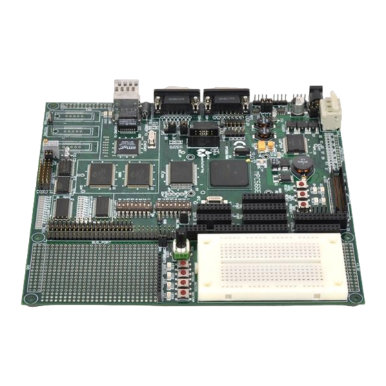
Figure 1-1. MPC566 EVB top view 1.1 Processor The microprocessor used on the MPC566EVB is the highly integrated Motorola PowerPC MPC566 32-bit microcontroller. The MPC566 implements a PPC ISA core with 1MByte UC3F flash, four UART channels, three Timing Processor Units (TPUs) -
Page 14: System Memory
User should note that the debug monitor firmware is installed in this flash device. Development tools or user application programs See Appendix A for block diagram of MPC53 MPC566EVB User’s Manual For More Information On This Product, Go to: www.freescale.com... -
Page 15: Sram
MPC566EVB dBUG debugger/monitor firmware (0x0090_0000 to 0x009F_FFFF). 1.2.2 SRAM The MPC566EVB has two 512 KByte device on the board (U2). It’s starting address is 0xFFF0_0000. The synchronous SRAM Memory Bank is composed of two128K x 32 memory devices. These... -
Page 16: Memory Device / Bank Selection And Configuration
Ethernet 0xFFF0_0000 - 0xFFFF_FFFF External SRAM 1MB 1.2.5.1 Memory Device / Bank Selection and Configuration. The MPC566EVB board has one internal memory bank, two external memory banks and a Peripheral memory bank that provide: • 36KByte Internal SRAM • MPC566 512K byte Internal FLASH Memory (U1) •... -
Page 17: Memory Bank Chip Select Configuration
(CS0) responds to any accesses after reset until the OR0 is written. Since CS0 (the global chip select) is connected to the Flash ROM (U6), the Flash ROM initially appears at address 0xFFF0_0000. The initialization routine then programs the chip-select logic, locates the Flash MPC566EVB User’s Manual For More Information On This Product, Go to: www.freescale.com... -
Page 18: Support Logic
Reset chapter for the respective RCW bit definitions. 1.3.2 Clock Circuitry The MPC566EVB board uses a 4MHz crystal (Y1 on the schematics) to provide the clock to the on-chip oscillator of the MPC566. In addition to the 4MHz crystal, there is also a 25MHz oscillator (Y3) which feeds the Ethernet chip (U20). -
Page 19: Ta Generation
Programming two interrupt sources with the same level and priority can result in undefined operation. The MPC566EVB hardware uses IRQ[0]/SGPIOC[0] to support the ABORT (Non Maskable Interrupt) function using the ABORT switch (SWITCH1 when BRK_EN jumper is inserted). This switch is used to force a non-maskable interrupt if the user's program execution should be aborted without issuing a RESET. -
Page 20: Power Oak K/I/S Hardware Options
VKAM and MPC566 back-up supply options. ‘I’ designated options refer to Interrupt operation options. ‘S’ designated options refer to MPC566 Reset or I/O signal connection options. Following is the summary table (also refer to MPC566EVB schematic): Table 1-3. K/I/S Option Table... -
Page 21: Communication Ports
Open The MPC535/6 has limited or no functionality for this module. See Appendix A 1.4 Communication Ports The MPC566EVB provides external interfaces for 4 SCI serial ports, 3 CAN ports and a 10/100T ethernet port. 1.4.1 COM1 - COM4 The MPC566 processor has two queued serial multi-channel modules (QSMCM_A and QSMCM_B) which provides four serial communications interfaces (SCI/UART). - Page 22 SCI_A_ RXD1 COM-1 Input SCI_A_ TXD2 COM-2 Output SCI_A_ RXD2 COM-2 Input SCI_B_ TXD1 COM-3 Output SCI_B_ RXD1 COM-3 Input SCI_B_ TXD2 COM-4 Output SCI_B_ RXD2 COM-4 Input 1-12 MPC566EVB User’s Manual For More Information On This Product, Go to: www.freescale.com...
-
Page 23: Can Ports And Options
Communication Ports 1.4.2 CAN PORTs and Options The MPC566EVB board provides 3 CAN transceivers with I/O ports: CAN_A, CAN_B, and CAN_C. CAN_A is supported by the PC33394 Power Oak CAN transceiver. The CAN_B and CAN_C ports are supported by Philips PCA82C250 1M Baud CAN transceivers. The MPC566 CAN_A port is directly interfaced to the Power Oak transceiver and can not be isolated easily. -
Page 24: 10/100T Ethernet Port
RJ45 jack J3 of the Ethernet port provides a direct to HUB type connection. The Ethernet cable provided with the MPC566EVB kit is a crossover type for direct connection of the EVB to a PC host network card. If connection to a HUB is desired, a standard Ethernet cable should be applied. -
Page 25: Bdm And Nexus Development Ports
IEEE-ISTO 5001 50 pin standard I/O connections and connector and the BDM port provides the standard 10 pin interface (refer to MPC566EVB schematic sheet 3 for details). User should observe that both ports can not be applied at the same time. Note that the NEXUS interface applies some of the MPC566 standard I/O signals from the MIOS module as alternate development port I/O signals. -
Page 26: Nexus Connector
2 definitions depending upon whether the connection is an Auxiliary only (Auxiliary In and Auxiliary Out) connection or a JTAG IEEE 1149.1 port with an Auxiliary Output port. NOTE The MPC56x parts do not support the JTAG IEEE 1149.1 configuration. 1-16 MPC566EVB User’s Manual For More Information On This Product, Go to: www.freescale.com... - Page 27 Exception: The RSTI input should have a 10K Ω pull-down resistor. This is in line with the proposed new standard. This signal is needed only if control of EPEE or B0EPEE is required by the Nexus tool. MPC566EVB User’s Manual 1-17 For More Information On This Product,...
- Page 28 — — VENDOR_IO0 SGPIOC[7]/ AC14 IRQOUT/LWP[0] VENDOR_IO1 EPEE & B0EPEE AF21 & AD20 TOOL_IO0 — — TOOL_IO1 — — TOOL_IO2 — — VREF VDD2.6 VALTREF VSTBY2.6 — 1-18 MPC566EVB User’s Manual For More Information On This Product, Go to: www.freescale.com...
-
Page 29: Connectors And User Components
The LCD Port provides a versatile connector to attach 80 or 160 character display modules and some graphics display modules with embedded controllers. Most LCD modules operate very The MPC535/6 has limited or no functionality for this module. See Appendix A MPC566EVB User’s Manual 1-19 For More Information On This Product,... - Page 30 Care should be used to verify proper connection and signal matching at the IDC Cable Connector and LCD_PORT. See the schematic to match this jumper setting to your LCD device connector. Contact support@axman.com for assistance applying a LCD module. 1-20 MPC566EVB User’s Manual For More Information On This Product, Go to: www.freescale.com...
-
Page 31: User Components
This feature is provided to support the Monitor ABORT operation to stop user code execution and return to the Monitor command prompt. When the option jumper is installed, depressing SW1 will cause a low active level to be applied to the MPC566 IRQ0. MPC566EVB User’s Manual 1-21 For More Information On This Product,... -
Page 32: Mpc566Evb Hardware Options
QADC_A Port. EPEE and BOEPEE CUTAWAY E0 The MPC566EVB board has the EPEE and BOEPEE signals connected by CUT_AWAY pad E0. This connection is for NEXUS port programming of the MPC566 internal flash. This connection will cause the CONFIG_SW position 7 or 8 to enable both signals. - Page 33 Freescale Semiconductor, Inc. Connectors and User Components BUS PORT (Continued) SIGNAL SIGNAL 2.6V MPC566EVB User’s Manual 1-23 For More Information On This Product, Go to: www.freescale.com...
-
Page 34: Tpu_Ports
40 pin header. CONTROL PORT SIGNAL SIGNAL TRST ALTREF BOEPEE EPEE TSIZ1 TSIZ0 BURST BDIP RSTCONF* The MPC535/6 has limited or no functionality for this module. See Appendix A 1-24 MPC566EVB User’s Manual For More Information On This Product, Go to: www.freescale.com... - Page 35 NEXUS MDO_6 MGPIO9 MGPIO8 NEXUS MDO_7 MGPIO7 MGPIO6 MGPIO5 MGPIO4 BDM VFLS0 (V4 option) BDM VFLS1 (V3 option) MGPIO3 MGPIO2 MGPIO1 MGPIO0 MPWM19 MPWM18 MPWM17 MPWM16 MPWM3 MPWM2 MPC566EVB User’s Manual 1-25 For More Information On This Product, Go to: www.freescale.com...
-
Page 36: Mios_Port
A_PQA3/AN55 A_PQB2/AN2 A_PQA2/AN54 A_PQB1/AN1 A_PQA1/AN53 A_PQB0/AN0 A_PQA0/AN52 QADC_B SIGNAL SIGNAL AN87 AN86 AN85 AN84 The MPC535/6 has limited or no functionality for this module. See Appendix A 1-26 MPC566EVB User’s Manual For More Information On This Product, Go to: www.freescale.com... -
Page 37: Qsm_Ports
A_TXD2 A_TXD1 COM1 A_ECK A_SCK POWER OAK POWER OAK A_MOSI A_MISO POWER OAK A_PCS3 A_PCS2 POWER OAK A_PCS1 A_PCS0 / QSM_B EVB USE SIGNAL SIGNAL EVB USE MPC566EVB User’s Manual 1-27 For More Information On This Product, Go to: www.freescale.com... -
Page 38: Mictor 1 - 3 Ports
The user can set this by changing the PLL Registers of the MPC566 in software. Software development on the MPC566EVB is best performed using a development tool connected to the BDM-PORT or NEXUS connector. This provides real-time access to all hardware, peripherals and memory on the board. - Page 39 Software Development debugging. User should review the demonstration and sample software tools provided separately in the MPC566EVB kit for high level debug capability. The development environment and procedure for best success is to place software to be tested into RAM memory. Execute software to be tested under Monitor or development tool control, then program into FLASH memory to execute new application when power is applied.
- Page 40 Freescale Semiconductor, Inc. Software Development 1-30 MPC566EVB User’s Manual For More Information On This Product, Go to: www.freescale.com...
-
Page 41: Chapter 2 Initialization And Setup
Freescale Semiconductor, Inc. Chapter 2 Initialization and Setup 2.1 System Configuration The MPC566 board requires the following items for minimum system configuration: • The MPC566EVB board (provided). • Power supply (provided). • RS232 compatible terminal or a PC with terminal emulation software. - Page 42 Freescale Semiconductor, Inc. System Configuration dBUG> 6 - 26 V Input Power RS-232 Terminal Or PC Figure 2-1. Minimum System Configuration MPC566EVB User’s Manual For More Information On This Product, Go to: www.freescale.com...
-
Page 43: Installation And Setup
You should have received: • MPC566EVB Single Board Computer • MPC566EVB User's Manual (this document) • One RS232 9-pin Serial Cable • One CAT5E Ethernet cable, crossover type •... - Page 44 TB1 pin 2 and 3 connections respectfully. TB1 pin 1 provides access the VIGN signal to the Power Oak, user should note ON jumper oper- MPC566EVB User’s Manual For More Information On This Product,...
-
Page 45: Selecting Terminal Baud Rate
The board is now ready to be connected to a PC/terminal. Use the RS232 serial cable to connect the PC/terminal to the MPC566EVB at COM-1. The cable has a 9-pin female D-sub terminal connector at one end and a 9-pin male D-sub connector at the other end. Connect the 9-pin male connector to connector COM-1 on the MPC566EVB board. -
Page 46: Using A Personal Computer As A Terminal
Pin 5 = Ground/Vss/Common Pin 7 and 8 = group connected for RTS/CTS flow control null back to host Pin 9 = open 2.3 MPC566EVB Jumper and Switch Setup Jumper settings are as follows: Note ‘*’ is used to indicate that default setting. - Page 47 Freescale Semiconductor, Inc. MPC566EVB Jumper and Switch Setup Table 2-2. Jumper Settings (Continued) Jumper Setting Function BDM being used runs at 2.6 volts. BRK_EN *inserted SWITCH1 will act as a debounced Non-Maskable Interrupt (ABORT) removed SWITCH1 is for user use...
-
Page 48: Reset Configuration Word And Configuration Switch (Config_Sw)
Freescale Semiconductor, Inc. MPC566EVB Jumper and Switch Setup Figure 2-3. Jumper Locations on the Board 2.3.1 Reset Configuration Word and Configuration Switch (CONFIG_SW) Configuration Switch provides several key external Reset Configuration Word (RCW)options and the programming enable options for programming the MPC566 internal flash memory. These switches provide a logic 0 or low level when off and a logic 1 or high level when on. - Page 49 Freescale Semiconductor, Inc. MPC566EVB Jumper and Switch Setup configuration options are only presented to the data bus during Hard Reset if enabled by CONFIG switch position 1. Note that MAP switch also has positions (5 and 8) that are part of the Reset Configuration Word.
-
Page 50: Memory Configuration (Map_Sw)
RW0, RW2, RW4 – 18, RW23 – 30 provide the user access to external Reset Configuration Word (RCW) bits not normally required for default MPC566EVB operation. The RW0 – 30 designations reflect the data bus D0 – D30 bit affected when the RCW word is enabled externally. All RW0 –... - Page 51 Freescale Semiconductor, Inc. System Power-up and Initial Operation dBUG> The board is now ready for operation under the control of the debugger as described in Chapter 3. If you do not get the above response, perform the following checks: 1. Make sure that the power supply is properly configured for polarity, voltage level and current capability (~300mA) and is connected to the board.
- Page 52 Freescale Semiconductor, Inc. System Power-up and Initial Operation 2-12 MPC566EVB User’s Manual For More Information On This Product, Go to: www.freescale.com...
-
Page 53: Using The Monitor/Debug Firmware
Chapter 3 Using the Monitor/Debug Firmware The MPC566EVB single board computer has a resident firmware package that provides a self-contained programming and operating environment. The firmware, named dBUG, provides the user with monitor/debug interface, inline assembler and disassembly, program download, register and memory manipulation, and I/O control functions. -
Page 54: Operational Procedure
Freescale Semiconductor, Inc. Operational Procedure Most commands can be recognized by using an abbreviated name. For instance, entering “h” is the same as entering “help”. Thus, it is not necessary to type the entire command name. The commands DI, GO, MD, STEP and TRACE are used repeatedly when debugging. dBUG recognizes this and allows for repeated execution of these commands with minimal typing. - Page 55 Freescale Semiconductor, Inc. Operational Procedure • Make sure the IP bit is set (switch 5 ON in MAP_SW). This will cause the board to boot out of external flash (where the dBUG code resides). • Turn power on to the board.
-
Page 56: System Initialization
Freescale Semiconductor, Inc. Operational Procedure Figure 3-1 shows the dUBG operational mode. Figure 3-1. Flow Diagram of dBUG Operational Mode. 3.2.2 System Initialization The act of powering up the board will initialize the system. The processor is reset and dBUG is invoked. -
Page 57: Hard Reset Button
If you did not get this response check the setup, refer to Section 2.4, “System Power-up and Initial Operation”. Other means can be used to re-initialize the MPC566EVB Computer Board firmware. These means are discussed in the following paragraphs. 3.2.2.1 Hard RESET Button. -
Page 58: Command Line Usage
Freescale Semiconductor, Inc. Command Line Usage 3.3 Command Line Usage The user interface to dBUG is the command line. A number of features have been implemented to achieve an easy and intuitive command line interface. dBUG assumes that an 80x24 ASCII character dumb terminal is used to connect to the debugger. - Page 59 Freescale Semiconductor, Inc. Commands Table 3-1. dBUG Command Summary MNEMONIC DESCRIPTION SYNTAX fl <command> dest <src> size Erase/Program External Flash go <addr> Execute gt addr Execute To hbr addr <-r> Hardware Breakpoint HELP help <command> Help ird <module.register> Internal Register Display irm module.register data...
- Page 60 Freescale Semiconductor, Inc. Commands Assembler Usage: ASM <<addr> stmt> The ASM command is a primitive assembler. The <stmt> is assembled and the resulting code placed at <addr>. This command has an interactive and non-interactive mode of operation. The value for address <addr> may be an absolute address specified as a hexadecimal value, or a symbol name.
- Page 61 Freescale Semiconductor, Inc. Commands Block Compare Usage: BC addr1 addr2 length The BC command compares two contiguous blocks of memory on a byte by byte basis. The first block starts at address addr1 and the second starts at address addr2, both of length bytes.
- Page 62 Freescale Semiconductor, Inc. Commands Block Fill Usage: BF<width> begin end data <inc> The BF command fills a contiguous block of memory starting at address begin, stopping at address end, with the value data. <Width> modifies the size of the data that is written. If no <width> is specified, the default of word sized data is used.
- Page 63 Freescale Semiconductor, Inc. Commands Block Move Usage: BM begin end dest The BM command moves a contiguous block of memory starting at address begin and stopping at address end to the new address dest. The BM command copies memory as a series of bytes, and does not alter the original block.
- Page 64 Freescale Semiconductor, Inc. Commands Breakpoints Usage: BR addr <-r> <-c count> <-t trigger> The BR command inserts or removes software breakpoints at address addr. The value for addr may be an absolute address specified as a hexadecimal value, or a symbol name. Count and trigger are numbers converted according to the user-defined radix, normally hexadecimal.
- Page 65 Freescale Semiconductor, Inc. Commands Block Search Usage: BS<width> begin end data The BS command searches a contiguous block of memory starting at address begin, stopping at address end, for the value data. <Width> modifies the size of the data that is compared during the search.
- Page 66 Freescale Semiconductor, Inc. Commands Data Conversion Usage: DC data The DC command displays the hexadecimal or decimal value data in hexadecimal, binary, and decimal notation. The value for data may be a symbol name or an absolute value. If an absolute value passed into the DC command is prefixed by ‘0x’, then data is interpreted as a hexadecimal value.
- Page 67 Freescale Semiconductor, Inc. Commands Disassemble Usage: DI <addr> The DI command disassembles target code pointed to by addr. The value for addr may be an absolute address specified as a hexadecimal value, or a symbol name. Wherever possible, the disassembler will use information from the symbol table to produce a more meaningful disassembly.
- Page 68 Freescale Semiconductor, Inc. Commands Download Console Usage: DL <offset> The DL command performs an S-record download of data obtained from the console typically through a serial port. The value for offset is converted according to the user-defined radix, normally hexadecimal.
- Page 69 Usage: DLDBUG The DLDBUG command will download the dBUG monitor to the MPC566EVB board. First it will erase all sectors of Flash that dBUG occupies, then it will download the code through the serial port. Upon asking if the user is sure they want to do this, the user should respond by typing “yes” if they want to continue. The DLDBUG command will work at baud rates up to and including 57600.
- Page 70 Freescale Semiconductor, Inc. Commands Download Network Usage: DN <-c> <-e> <-i> <-s> <-o offset> <filename> The DN command downloads code from the network. The DN command handle files which are either S-record, COFF, ELF or Image formats. The DN command uses Trivial File Transfer Protocol (TFTP) to transfer files from a network host.
- Page 71 Freescale Semiconductor, Inc. Commands Erase/Program Flash Usage: FL (e)rase addr bytes FL (w)rite dest src bytes The FL command is used to erase the external flash, write to external flash, and display flash device information. Erase and Write operations must be done in sector blocks. dBUG assumes that the user has erased enough memory before writing to it.
- Page 72 Freescale Semiconductor, Inc. Commands Execute Usage: GO <addr> The GO command executes target code starting at address addr. The value for addr may be an absolute address specified as a hexadecimal value, or a symbol name. If no argument is provided, the GO command begins executing instructions at the current program counter.
- Page 73 Freescale Semiconductor, Inc. Commands Execute To Usage: GT addr The GT command inserts a temporary software breakpoint at addr and then executes target code starting at the current program counter. The value for addr may be an absolute address specified as a hexadecimal value, or a symbol name.
- Page 74 Freescale Semiconductor, Inc. Commands HELP Help Usage: HELP <command> The HELP command displays a brief syntax of the commands available within dBUG. In addition, the address of where user code may start is given. If command is provided, then a brief listing of the syntax of the specified command is displayed.
- Page 75 Freescale Semiconductor, Inc. Commands Internal Register Display Usage: IRD <module.register> This command displays the internal registers of different modules inside the MPC500. In the command line, module refers to the module name where the register is located and register refers to the specific register to display.
- Page 76 Freescale Semiconductor, Inc. Commands Internal Register Modify Usage: IRM module.register data This command modifies the contents of the internal registers of different modules inside the MPC500. In the command line, module refers to the module name where the register is located and register refers to the specific register to modify.
- Page 77 Freescale Semiconductor, Inc. Commands Loop Read Usage: LR<width> addr The LR command continually reads the data at addr until a key is pressed. The optional <width> specifies the size of the data to be read. If no <width> is specified, the command defaults to reading word sized data.
- Page 78 Freescale Semiconductor, Inc. Commands Loop Write Usage: LW<width> addr data The LW command continually writes data to addr. The optional width specifies the size of the access to memory. The default access size is a word. Examples: To continually write the data 0x1234_5678 to address 0xFFF2_0000, the command is:...
- Page 79 Freescale Semiconductor, Inc. Commands Memory Display Usage: MD<width> <begin> <end> The MD command displays a contiguous block of memory starting at address begin and stopping at address end. The values for addresses begin and end may be absolute addresses specified as hexadecimal values, or symbol names.
- Page 80 Freescale Semiconductor, Inc. Commands Memory Modify Usage: MM<width> addr <data> The MM command modifies memory at the address addr. The value for addr may be an absolute address specified as a hexadecimal value, or a symbol name. Width specifies the size of the data that is modified.
- Page 81 Freescale Semiconductor, Inc. Commands MMAP Memory Map Display Usage: mmap This command displays the memory map information for the MPC566 evaluation board. The information displayed includes the type of memory, the start and end address of the memory, and the port size of the memory. The display also includes information on how the Chip-selects are used on the board.
- Page 82 Freescale Semiconductor, Inc. Commands Register Display Usage: RD <reg> The RD command displays the register set of the target. If no argument for reg is provided, then all registers are displayed. Otherwise, the value for reg is displayed. dBUG preserves the registers by storing a copy of the register set in a buffer. The RD command displays register values from the register buffer.
- Page 83 Freescale Semiconductor, Inc. Commands Register Modify Usage: RM reg data The RM command modifies the contents of the register reg to data. The value for reg is the name of the register, and the value for data may be a symbol name, or it is converted according to the user-defined radix, normally hexadecimal.
- Page 84 Freescale Semiconductor, Inc. Commands RESET Reset the Board and dBUG Usage: RESET The RESET command resets dBUG to it’s initial power-on states. The RESET command executes the same sequence of code that occurs at power-on. If the RESET command fails to reset the system adequately, cycle the power or press the reset button.
- Page 85 Freescale Semiconductor, Inc. Commands Set Configurations Usage: SET <option value> The SET command allows the setting of user-configurable options within dBUG. With no arguments, SET displays the options and values available. The SHOW command displays the settings in the appropriate format. The standard set of options is listed below.
- Page 86 Freescale Semiconductor, Inc. Commands SHOW Show Configurations Usage: SHOW <option> The SHOW command displays the settings of the user-configurable options within dBUG. When no option is provided, SHOW displays all options and values. Examples: To display all options and settings, the command is:...
- Page 87 Freescale Semiconductor, Inc. Commands STEP Step Over Usage: STEP The STEP command can be used to “step over” a subroutine call, rather than tracing every instruction in the subroutine. The ST command sets a temporary software breakpoint one instruction beyond the current program counter and then executes the target code. This command only works when executing code in SRAM.
- Page 88 Freescale Semiconductor, Inc. Commands SYMBOL Symbol Name Management Usage: SYMBOL <symb> <-a symb value> <-r symb> <-c|l|s> The SYMBOL command adds or removes symbol names from the symbol table. If only a symbol name is provided to the SYMBOL command, then the symbol table is searched for a match on the symbol name and its information displayed.
- Page 89 Freescale Semiconductor, Inc. Commands TRACE Trace Into Usage: TRACE <num> The TRACE command allows single-instruction execution. If num is provided, then num instructions are executed before control is handed back to dBUG. The value for num is a decimal number.
- Page 90 Freescale Semiconductor, Inc. Commands VERSION Display dBUG Version Usage: VERSION The VERSION command displays the version information for dBUG. The dBUG version, build number and build date are all given. The version number is separated by a decimal, for example, “v 2b.1c.1a”.
-
Page 91: System Call Functions
Freescale Semiconductor, Inc. System Call Functions 3.5 System Call Functions An additional utility within the dBUG firmware is a function called the System Call handler. This function can be called by the user program to utilize various routines within dBUG, to perform a special task, and to return control to dBUG. -
Page 92: In_Stat
Freescale Semiconductor, Inc. System Call Functions /* assume r3 contains the character */ asm(“ addi r10, r0, 0x0000”); Selects the function asm(“ sc”); The character is returned in r3 3.5.3 IN_STAT This function (function code 0x0001) checks if an input character is present to receive. A value of zero is returned in r3 when no character is present. -
Page 93: Exit_To_Dbug
Freescale Semiconductor, Inc. System Call Functions C example: board_isr_remove (void *handler) asm( "addi r10,r0,0x0041"); asm( "sc"); 3.5.6 EXIT_TO_dBUG This function transfers the control back to the dBUG, by terminating the user code. The register context is preserved. C example (see “scif.s”file : anything in R10 besides 0x0000, 0x0001, 0x0020, 0x0030, 0x0031,... - Page 94 Freescale Semiconductor, Inc. System Call Functions 3-42 MPC564EVB User’s Manual For More Information On This Product, Go to: www.freescale.com...
- Page 95 Freescale Semiconductor, Inc. Appendix A MPC535/536 Emulation The MPC5646EVB can be used to emulate the MPC535 and MPC536 processors. This appendix will highlight the differences between the processors. Several modules present in the MPC566 are not available in the MPC535/6, so the user should not reference those modules.
- Page 96 USIU MPC5xx Nexus 4-Kbyte CALRAM_B Core 4-Kbyte Overlay L-BUS 32K CALRAM_A 28 Kbytes SRAM No Overlay 4-Kbyte Overlay QADC64E QADC64E UIMB QSMCM QSMCM J1850 w/AMUX w/AMUX IMB3 MIOS14 MPC566EVB User’s Manual For More Information On This Product, Go to: www.freescale.com...
-
Page 97: B.1 Required Network Parameters
Freescale Semiconductor, Inc. Appendix B Configuring dBUG for Network Downloads The dBUG module has the ability to perform downloads over an Ethernet network using the Trivial File Transfer Protocol, TFTP (NOTE: this requires a TFTP server to be running on the host attached to the board). -
Page 98: B.3 Troubleshooting Network Problems
Freescale Semiconductor, Inc. Troubleshooting Network Problems set gateway <gateway IP> set netmask <netmask> set ethaddr <addr> For example, the TFTP server is named ‘santafe’ and has IP address 123.45.67.1. The board is assigned the IP address of 123.45.68.15. The gateway IP address is 123.45.68.250, and the netmask is 255.255.255.0. - Page 99 Freescale Semiconductor, Inc. Troubleshooting Network Problems fail, and probably other severe network problems. Make certain the client IP address is unique for the board. Check for proper insertion or connection of the network cable. Is the status LED lit indicating that network traffic is present? Check for proper configuration and operation of the TFTP server.
- Page 100 Freescale Semiconductor, Inc. Troubleshooting Network Problems MPC564EVB User’s Manual For More Information On This Product, Go to: www.freescale.com...
Need help?
Do you have a question about the MPC566EVB and is the answer not in the manual?
Questions and answers