
Related Manuals for AEMC 400D-6


Summary of Contents for AEMC 400D-6
- Page 1 400D-6 ® DIGITAL FLEXPROBE 400D-10 400D-24 4000D-14 4000D-24 ENGLISH User Manual GlobalTestSupply www. .com Find Quality Products Online at: sales@GlobalTestSupply.com...
- Page 2 Statement of Compliance Chauvin Arnoux ® , Inc. d.b.a. AEMC ® Instruments certifies that this instrument has been calibrated using standards and instruments traceable to international standards. We guarantee that at the time of shipping your instrument has met its published specifications.
-
Page 3: Table Of Contents
Table of Contents 1. INTRODUCTION ................4 1.1 International Electrical Symbols ..........5 1.2 Definition of Measurement Categories ........5 1.3 Receiving Your Shipment ............6 1.4 Ordering Information ..............6 1.4.1 Accessories and Replacement Parts ......6 2. PRODUCT FEATURES ..............7 2.1 Description ................7 2.2 Control Features ...............8 3. OPERATION .................. 10 3.1 Measurement Principle ............10 3.2 Use ..................10 3.2.1 Connection ..............10... - Page 4 5. MAINTENANCE ................17 5.1 Cleaning ..................17 5.2 Replacing the Batteries ............17 5.3 Repair and Calibration ............18 5.4 Technical and Sales Assistance ..........18 5.5 Limited Warranty ..............19 5.6 Warranty Repairs ..............19 ® Digital Flexprobe Models 400D & 4000D GlobalTestSupply www. .com Find Quality Products Online at: sales@GlobalTestSupply.com...
-
Page 5: Introduction
CHAPTER 1 INTRODUCTION Thank you for purchasing an AEMC ® Digital Flexbprobe. For best results and for your safety, read the enclosed operating instructions carefully and comply with the precautions for use. PRECAUTIONS BEFORE USE This instrument is protected against voltages of not more than... -
Page 6: International Electrical Symbols
International Electrical Symbols Signifies that the instrument is protected by double or reinforced insulation. CAUTION - Risk of Danger! Indicates a WARNING and that the operator must refer to the user manual for instructions before operating the instrument in all cases where this symbol is marked. -
Page 7: Ordering Information
Ordering Information ® Digital FlexProbe (MiniFlex) Model 400D-6 w/6 ft Lead (TRMS, 4A , 40A , 400A ) ..........Cat. #2153.30 ® Digital FlexProbe (MiniFlex) Model 400D-10 w/6 ft Lead (TRMS, 4A , 40A , 400A ) ..........Cat. #2153.31 Digital FlexProbe ®... -
Page 8: Product Features
CHAPTER 2 PRODUCT FEATURES Description An ideal addition to the electrician’s tool kit, the Digital FlexProbe ® series can be used for TRMS AC current measurements from 20mA to 4000A, and are rated 600V CAT IV. They provide a welcomed solution when accessing electrical conductors is difficult and in tight places. -
Page 9: Control Features
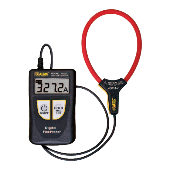
Control Features 4000 A MODEL 400 TRMS CURRENT METER HOLD HOLD (>2s) Digital FlexProbe ® Miniflex example shown 1. Flexible sensor - Model 400D (6", 10", 24") - Model 4000D (14", 24") 2. Sensor opening/closing lever 3. Shielded lead 4. Protective housing 5. LCD display 6. ON/OFF button 7. HOLD button ® Digital Flexprobe Models 400D &... - Page 10 On the back of the protective housing is a notch for the attachment of a belt clip (optional). With the Multifix magnetic mounting accessory, you can position your Digital FlexProbe ® anywhere, leaving both hands free. The Multifix can be used to: •...
-
Page 11: Operation
CHAPTER 3 OPERATION Measurement Principle The flexible sensor is based on the Rogowski coil. This principle combines: • Excellent linearity with no saturation effect (therefore no heating) • Light-weight (no magnetic circuit) 3.2.1 Connection 1. Press the locking clip(s) to open the sensor. 2. Place the sensor around the conductor through which the current to be measured flows (only one conductor in the sensor), then close the sensor. 3. -
Page 12: Freezing The Measurement
If the measurement exceeds the display capacity (4000A), the device dis- plays 3999, blinking. If the measurement is too low (see § 3.2), the device displays dashes. If the edges of the signal are too steep, or its peak factor is too large, the device displays OL. -
Page 13: Search For Maximum
3.2.4 Search for Maximum To search for a maximum, for example a spike lasting at least 100ms, press the HOLD (MAX > 2s) button for more than two seconds. The Max symbol will display and the instrument will begin measuring. The Digital Flexprobe ®... -
Page 14: Specifications
External AC magnetic field none Position of the conductor centered in the measurement coil Shape of the measurement coil nearly circular Electrical Model 400D-6 / 400D-10 / 400D-24 Display Range 400A Measurement Range 0.020 to 3.999A 4.00 to 39.99A 40.0 to 399.9A Measurement Range (max) 0.100 to 3.999A... -
Page 15: Variations In Range Of Use
Variations in Range of Use Quantity of influence Range of influence Battery voltage 1.8 to 2V Temperature 32 to 122°F (0 to 50°C) Relative humidity 10 to 90% RH 10 to 20Hz 20 to 30Hz Frequency response 30 to 400Hz 400 to 1000Hz 1000 to 3000Hz Position of the conductor in the... -
Page 16: Typical Frequency Response Curves
Typical Frequency Response Curves (at 39A 10 % -10 % -20 % -30 % -40 % -50 % Power Supply The device can be powered by either: • Two 1.5V (AAA) alkaline batteries • Two NiMH storage batteries of the same size The nominal operating voltage is between 1.8V and 3.2V. -
Page 17: Environmental
Sensor Length: 400D-6: 6" (170mm) 400D-10: 10" (250mm) 400D-24: 24" (610mm) 4000D-14: 14" (350mm) 4000D-24: 24" (610mm) Sensor Diameter: 400D-6: Ø 1.77" (45mm) 400D-10: Ø 2.75" (70mm) 400D-24: Ø 8" (190mm) 4000D-14 : Ø 3.94" (100mm) 4000D-24 : Ø 8" (190mm) Weight: 0.29 lbs (130g) approx (MiniFlex) -
Page 18: Digital Flexprobe ® Models 400D & 4000D
CHAPTER 5 MAINTENANCE Use only factory specified replacement parts. AEMC ® will not be held responsible for any accident, incident, or malfunction following a repair done other than by its service center or by an approved repair center. Cleaning Disconnect the instrument from any source of electricity. -
Page 19: Repair And Calibration
Repair and Calibration To ensure that your instrument meets factory specifications, we recommend that it be scheduled back to our factory Service Center at one-year intervals for recalibration, or as required by other standards or internal procedures. For instrument repair and calibration: You must contact our Service Center for a Customer Service Authorization Number (CSA#). -
Page 20: Limited Warranty
® in manufacture. This limited warranty is given by AEMC Instruments, not by the distributor from whom it was purchased. This warranty is void if the unit...
Need help?
Do you have a question about the 400D-6 and is the answer not in the manual?
Questions and answers