
Related Manuals for Supermicro SuperWorkstation 7046A-HR+


Summary of Contents for Supermicro SuperWorkstation 7046A-HR+
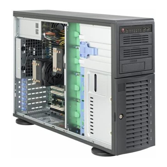
- Page 1 UPER ® 7046A-HR+ uper orkstation 7046A-HR+F uper orkstation USER’S MANUAL...
- Page 2 Please Note: For the most up-to-date version of this manual, please see our web site at www.supermicro.com. Super Micro Computer, Inc. ("Supermicro") reserves the right to make changes to the product described in this manual at any time and without notice. This product, including software, if any, and documentation may not, in whole or in part, be copied, photocopied, reproduced, translated or reduced to any medium or machine without prior written consent.
-
Page 3: About This Manual
Preface Preface About This Manual This manual is written for professional system integrators and PC technicians. It provides information for the installation and use of the SuperWorkstation 7046A- HR+/7046A-HR+F. Installation and maintainance should be performed by experi- enced technicians only. The SuperWorkstation 7046A-HR+/7046A-HR+F is a high-end workstation based on the SC745TQ-R1400B-SQ chassis and the X8DAH+/X8DAH+-F dual processor serverboard. - Page 4 uper orkstation 7046A-HR+/7046A-HR+F User's Manual Chapter 5: Advanced Serverboard Setup Chapter 5 provides detailed information on the X8DAH+/X8DAH+-F serverboard, including the locations and functions of connections, headers and jumpers. Refer to this chapter when adding or removing processors or main memory and when reconfi...
- Page 5 Preface Notes...
-
Page 6: Table Of Contents
Other Features ....................1-3 Server Chassis Features ................1-3 System Power ....................1-3 Front Control Panel ..................1-3 Cooling System ....................1-3 Contacting Supermicro ..................1-5 Chapter 2 Server Installation Overview ......................2-1 Unpacking the System ..................2-1 Preparing for Setup ..................2-1 Choosing a Setup Location ................ - Page 7 Table of Contents Chapter 3 System Interface Overview ......................3-1 Control Panel Buttons ..................3-1 Power ......................3-1 Reset ....................... 3-1 Control Panel LEDs ..................3-2 Power ......................3-2 HDD ......................... 3-2 NIC1 ........................ 3-2 NIC2 ........................ 3-2 Overheat/Fan Fail ................... 3-3 Power Fail .......................
- Page 8 uper orkstation 7046A-HR+/7046A-HR+F User's Manual Connector Defi nitions ................... 5-13 Main ATX Power Supply Connector ............5-13 Processor Power Connector ..............5-13 Power Button .................... 5-13 Reset Button ..................... 5-13 Power Fail LED ..................5-14 Overheat/Fan Fail LED (OH)..............5-14 NIC2 (JLAN2) LED ...................
- Page 9 Table of Contents 5-13 Installing Software ..................5-24 Supero Doctor III ................... 5-25 Chapter 6 Advanced Chassis Setup Static-Sensitive Devices .................. 6-1 Precautions ..................... 6-1 Front Control Panel ..................6-3 System Fans ....................6-4 Fan Failure ...................... 6-4 Drive Bay Installation ..................6-5 SATA Drives ....................
- Page 10 uper orkstation 7046A-HR+/7046A-HR+F User's Manual Notes...
-
Page 11: Chapter 1 Introduction
X8DAH+/X8DAH+-F dual processor serverboard. Please refer to our web site for information on operating systems that have been certifi ed for use with the system (www.supermicro.com). In addition to the serverboard and chassis, various hardware components have been included with the 7046A-HR+/7046A-HR+F, as listed below: •... -
Page 12: Serverboard Features
The X8DAH+/X8DAH+-F supports single or dual Intel® Xeon® 5500 (LGA1366 socket) processors. Please refer to the serverboard description pages on our web site for a complete listing of supported processors (www.supermicro.com). Memory The serverboard has eighteen DIMM slots that can support up to 144 GB of DDR3- 1333/1066/800 registered ECC SDRAM. -
Page 13: Graphics Controller
Chapter 1: Introduction Graphics Controller The X8DAH+-F (only) features an integrated Matrox G200eW graphics controller for onboard graphics. Other Features Other onboard features that promote system health include onboard voltage moni- tors, a chassis intrusion header, auto-switching voltage regulators, chassis and CPU overheat sensors, virus protection and BIOS rescue. -
Page 14: System Block Diagram
uper orkstation 7046A-HR+/7046A-HR+F User's Manual Figure 1-1. Intel 5520/ICH10R Chipset: System Block Diagram Note: This is a general block diagram. Please see Chapter 5 for details. CPU1 CPU2 Slot#5 PCI-E x4 Slot#2 PCI-E x16 Ports 1&2 Ports 3~6 Slot#7 PCI-E x8 Ports 3&4 Intel 5520 Intel 5520... -
Page 15: Contacting Supermicro
Super Micro Computer, Inc. 980 Rock Ave. San Jose, CA 95131 U.S.A. Tel: +1 (408) 503-8000 Fax: +1 (408) 503-8008 Email: marketing@supermicro.com (General Information) support@supermicro.com (Technical Support) Web Site: www.supermicro.com Europe Address: Super Micro Computer B.V. Het Sterrenbeeld 28, 5215 ML... - Page 16 uper orkstation 7046A-HR+/7046A-HR+F User's Manual Notes...
-
Page 17: Chapter 2 Server Installation
Chapter 2: Server Installation Chapter 2 Server Installation Overview This chapter provides a quick setup checklist to get your SuperWorkstation 7046A- HR+/7046A-HR+F up and running. Following these steps in the order given should enable you to have the system operational within a minimum amount of time. This quick setup assumes that your system has come to you with the proces- sors and memory preinstalled. -
Page 18: Choosing A Setup Location
uper orkstation 7046A-HR+/7046A-HR+F User's Manual Choosing a Setup Location • Leave enough clearance in front of the rack to enable you to open the front door completely (~25 inches) and approximately 30 inches of clearance in the back of the rack to allow for suffi cient airfl ow and ease in servicing. •... -
Page 19: Rack Mounting Considerations
Chapter 2: Server Installation • Allow the hot plug SATA drives and power supply modules to cool before touch- ing them. • Always keep the rack's front door and all panels and components on the servers closed when not servicing to maintain proper cooling. Rack Mounting Considerations Ambient Operating Temperature If installed in a closed or multi-unit rack assembly, the ambient operating tempera-... -
Page 20: Installing The System Into A Rack
uper orkstation 7046A-HR+/7046A-HR+F User's Manual Installing the System into a Rack This section provides information on installing the system into a rack unit. Rack installation requires the use of the optional rackmount kit. If the system has already been mounted into a rack or if you are using it as a tower, you can skip ahead to Sections 2-5 and 2-6. -
Page 21: Installing The Chassis Rails
Chapter 2: Server Installation Installing the Chassis Rails You will need to remove the top cover and the feet to add rack rails to the chassis. First, remove the top and right covers (top and left covers when standing as a tower chassis) by fi... -
Page 22: Installing The Rack Rails
uper orkstation 7046A-HR+/7046A-HR+F User's Manual Figure 2-3. Installing the Rails to the Chassis Installing the Rack Rails Determine where you want to place the SuperWorkstation 7046A-HR+/7046A-HR+F in the rack. (See Rack and Server Precautions in Section 2-3.) Position the fi xed rack rail/sliding rail guide assemblies at the desired location in the rack, keeping the sliding rail guide facing the inside of the rack. -
Page 23: Installing The Server Into The Rack
Chapter 2: Server Installation Installing the Server into the Rack You should now have rails attached to both the chassis and the rack unit. The next step is to install the server into the rack. You should have two brackets in the rack mount kit. -
Page 24: Checking The Serverboard Setup
uper orkstation 7046A-HR+/7046A-HR+F User's Manual Checking the Serverboard Setup After setting up the the system, you will need to open the unit to make sure the serverboard is properly installed and all the connections have been made. Accessing the Inside of the System If rack mounted, fi... -
Page 25: Checking The Drive Bay Setup
Chapter 2: Server Installation Checking the Drive Bay Setup Next, you should check to make sure the peripheral drives and then SATA drives and backplane have been properly installed and all connections have been made. Checking the Drives All drives can be accessed from the front of the server. For servicing the CD- ROM drives and fl... - Page 26 uper orkstation 7046A-HR+/7046A-HR+F User's Manual Figure 2-5. Accessing the Inside of the System (Rack Confi guration shown) 2-10...
-
Page 27: Chapter 3 System Interface
Chapter 3: System Interface Chapter 3 System Interface Overview The control panel on the 7046A-HR+/7046A-HR+F has several LEDs and two but- tons. There are also two LEDs on each SATA drive carrier. These LEDs keep you constantly informed of the overall status of the system and the activity and health of specifi... -
Page 28: Control Panel Leds
uper orkstation 7046A-HR+/7046A-HR+F User's Manual Control Panel LEDs The control panel located on the front of the SC745 chassis has six LEDs that provide you with critical information related to different parts of the system. This section explains what each LED indicates when illuminated and any corrective ac- tion you may need to take. -
Page 29: Overheat/Fan Fail
Chapter 3: System Interface Overheat/Fan Fail When this LED fl ashes, it indicates a fan failure. When on continuously it indicates an overheat condition, which may be caused by cables obstructing the airfl ow in the system or the ambient room temperature being too warm. Check the routing of the cables and make sure all fans are present and operating normally. - Page 30 uper orkstation 7046A-HR+/7046A-HR+F User's Manual Notes...
-
Page 31: Chapter 4 System Safety
Chapter 4: System Safety Chapter 4 System Safety Electrical Safety Precautions Basic electrical safety precautions should be followed to protect yourself from harm and the SuperWorkstation 7046A-HR+/7046A-HR+F from damage: • Be aware of the locations of the power on/off switch on the chassis as well as the room's emergency power-off switch, disconnection switch or electrical outlet. -
Page 32: General Safety Precautions
uper orkstation 7046A-HR+/7046A-HR+F User's Manual • This product may be connected to an IT power system. In all cases, make sure that the unit is also reliably connected to Earth (ground). • Serverboard Battery: CAUTION - There is a danger of explosion if the onboard battery is installed upside down, which will reverse its polarites (see Figure 4-1). -
Page 33: Esd Precautions
Chapter 4: System Safety • Remove any jewelry or metal objects from your body, which are excellent metal conductors that can create short circuits and harm you if they come into contact with printed circuit boards or areas where power is present. •... -
Page 34: Operating Precautions
uper orkstation 7046A-HR+/7046A-HR+F User's Manual Operating Precautions Care must be taken to assure that the chassis cover is in place when the 7046A- HR+/7046A-HR+F is operating to assure proper cooling. Out of warranty damage to the system can occur if this practice is not strictly followed. Figure 4-1. -
Page 35: Chapter 5 Advanced Serverboard Setup
Chapter 5: Advanced Serverboard Setup Chapter 5 Advanced Serverboard Setup This chapter covers the steps required to install the serverboard into the chassis, connect the data and power cables and install add-on cards. All serverboard jumpers and connections are also described. A layout and quick reference chart are included in this chapter for your reference. -
Page 36: Serverboard Installation
uper orkstation 7046A-HR+/7046A-HR+F User's Manual Serverboard Installation This section explains the fi rst step of physically mounting the X8DAH+/X8DAH+F into the SC745TQ-R1400B-SQ chassis. Following the steps in the order given will eliminate the most common problems encountered in such an installation. To remove the serverboard, follow the procedure in reverse order. -
Page 37: Connecting Power Cables
Chapter 5: Advanced Serverboard Setup • SATA drive data cables (I-SATA0 ~ I-SATA5) • Control Panel cable (JF1) • USB cable for front side access (USB6/7) Important! Make sure the the cables do not come into contact with the fans. Connecting Power Cables The X8DAH+/X8DAH+F has a 24-pin primary power supply connector (JPW1) for connection to the ATX power supply. -
Page 38: I/O Ports
uper orkstation 7046A-HR+/7046A-HR+F User's Manual I/O Ports The I/O ports are color coded in conformance with the PC 99 specifi cation. Figure 5-2. I/O Ports IO Ports Keyboard (Purple) USB Port 5 PS/2 Mouse (Green) LAN Port 1 COM Port 1 LAN Port 2 VGA Port (7046A-HR+F only) Side Surround (Grey) -
Page 39: Installing A Processor And Heatsink
CPU socket cap is in place and none of the socket pins are bent; otherwise, contact your retailer immediately. • Refer to the Supermicro web site for updates on CPU support. Installing an LGA1366 Processor Press the socket clip to release... - Page 40 uper orkstation 7046A-HR+/7046A-HR+F User's Manual After removing the plastic cap, use your thumb and the index fi nger to hold the CPU at the north and south center edges. Align the CPU key (the semi-circle cutout) with the socket key (the notch below the gold color dot on the side of the socket).
-
Page 41: Installing A Cpu Heatsink
Chapter 5: Advanced Serverboard Setup Installing a CPU Heatsink Installing the Heatsink Remove power from the system and unplug the AC power cord from the power supply. Screw #1 Do not apply any thermal grease to the heatsink or the CPU die; the required amount has already been applied. -
Page 42: Memory Support
uper orkstation 7046A-HR+/7046A-HR+F User's Manual Installing Memory CAUTION! Exercise extreme care when installing or removing DIMM modules to prevent any possible damage. Memory Support The X8DAH+/X8DAH+F supports up to 144 GB of DDR3 1333/1066/800 registered ECC SDRAM in 18 DIMM slots. Three-way interleaved memory is supported. For optimal memory performance, install DIMMs three at a time. -
Page 43: Memory Support
Chapter 5: Advanced Serverboard Setup Memory Support The X8DAH+/X8DAH+F supports up to 144 GB Registered ECC DDR3- 1333/1066/800 MHz registered ECC SDRAM in 18 DIMM slots. DIMM sizes of 8 GB, 4 GB, 2 GB and 1 GB are supported. Populating DIMMs Follow the tables below when installing memory. -
Page 44: Installing Pci Expansion Cards
uper orkstation 7046A-HR+/7046A-HR+F User's Manual Notes: Due to OS limitations, some operating systems may not show more than 4 GB of memory. Due to memory allocation to system devices, the amount of memory that remains available for operational use will be reduced when 4 GB of RAM is used. The reduction in memory availability is disproportional. -
Page 45: Serverboard Details
Chapter 5: Advanced Serverboard Setup Serverboard Details Figure 5-4. X8DAH+ Layout (not drawn to scale) JPW1 JPW2 JPW3 P2 DIMM1C JPI2C1 FAN6 FAN5 P2 DIMM2C FAN7/CPU1 FAN P2 DIMM3C JUSB1 P2 DIMM1B FAN1 P2 DIMM2B KB/MS P2 DIMM3B CPU1 P2 DIMM1A P2 DIMM2A FAN2 P2 DIMM3A... -
Page 46: X8Dah+ Quick Reference
uper orkstation 7046A-HR+/7046A-HR+F User's Manual X8DAH+ Quick Reference Jumper Description Default Setting JBT1 CMOS Clear Open (Normal) C1/JI SMB to PCI/PCI-E Slots Open/Open (Disabled) JPG1 VGA Enable/Disable Pins 1-2 (Enabled) JPI1 1394-1/1394 (FireWire) Enable/Disable Pins 1-2 (Enabled) JPL1 LAN1/2 Enable/Disable Pins 1-2 (Enabled) JWD1 Watch Dog... -
Page 47: Connector Defi Nitions
Chapter 5: Advanced Serverboard Setup Connector Defi nitions ATX Power 24-pin Connector Pin Defi nitions Pin# Defi nition Pin # Defi nition Main ATX Power Supply +3.3V +3.3V Connector -12V +3.3V The primary power supply connector (JPW1) meets the SSI (Superset ATX) PS_ON EPS 12V specifi... -
Page 48: Power Fail Led
uper orkstation 7046A-HR+/7046A-HR+F User's Manual Power Fail LED PWR Fail LED Pin Defi nitions (JF1) The Power Fail LED connection is Pin# Defi nition located on pins 5 and 6 of JF1. Re- fer to the table on the right for pin Ground defi... -
Page 49: Power On Led
Chapter 5: Advanced Serverboard Setup Power On LED Power LED Pin Defi nitions (JF1) The Power On LED connector is lo- Pin# Defi nition cated on pins 15 and 16 of JF1 (use 5V Stby JLED for a 3-pin connector). This Control connection is used to provide LED indication of power being supplied to... -
Page 50: Chassis Intrusion
uper orkstation 7046A-HR+/7046A-HR+F User's Manual Chassis Intrusion Chassis Intrusion Pin Defi nitions The Chassis Intrusion header is des- Pin# Defi nition ignated JL1. Attach an appropriate Intrusion Input cable from the chassis to inform you Ground of a chassis intrusion when the chas- sis is opened LAN1/2 (Ethernet Ports) Two Ethernet ports (designated LAN1... -
Page 51: Universal Serial Bus (Usb)
Chapter 5: Advanced Serverboard Setup Universal Serial Bus (USB) Rear I/O USB Ports (USB 0/1, 2~5) Six Universal Serial Bus ports (USB Pin# Defi nitions 0/1, 2~5) are located on the I/O back panel. Additionally, four USB headers (USB 6/7, 8, 9) are on the serverboard to provide front chassis access (ca- Ground bles are not included). -
Page 52: Power Smb (I C) Connector
uper orkstation 7046A-HR+/7046A-HR+F User's Manual PWR SMB Power SMB (I C) Connector Pin Defi nitions Pin# Defi nition The Power System Management Bus Clock C) connector (JPI C) may be used to monitor the status of the power Data supply, fans and system tempera- PWR Fail tures. -
Page 53: 5-10 Jumper Settings
Chapter 5: Advanced Serverboard Setup 5-10 Jumper Settings Explanation of Jumpers To modify the operation of the serverboard, jumpers can be used Connector to choose between optional settings. Pins Jumpers create shorts between two pins to change the function of the con- nector. -
Page 54: Lan1/2 Enable/Disable
uper orkstation 7046A-HR+/7046A-HR+F User's Manual LAN1/2 Enable/Disable LAN1/2 Enable/Disable Jumper Settings Change the setting of jumper JPL1 to Jumper Setting Defi nition enable or disable the LAN1/LAN2 Eth- Pins 1-2 Enabled ernets port on the serverboard. See the Pins 2-3 Disabled table on the right for jumper settings. -
Page 55: 1394A-1/1394A-2 Enable/Disable
Chapter 5: Advanced Serverboard Setup 1394a-1/1394a-2 Enable/Disable FireWire Enable/Disable Use jumper JPI1 to enable the 1394a Jumper Settings connections at CNF1(1394a-1)/CNF2 Jumper Setting Defi nition (1394a-2) on the serverboard. See the Enabled (Default) table on the right for jumper settings. Disabled 5-11 Onboard Indicators Activity LED... -
Page 56: 5-12 Floppy And Sata Ports
uper orkstation 7046A-HR+/7046A-HR+F User's Manual 5-12 Floppy and SATA Ports Use the following information to connect the IDE hard disk drive cables. • A red mark on a wire typically designates the location of pin 1. • The 80-wire ATA100/66 IDE hard disk drive cable that came with your system has two connectors to support two drives. -
Page 57: Sata Ports
Chapter 5: Advanced Serverboard Setup SATA Port Pin Defi nitions Pin # Defi nition SATA Ports Ground There are no jumpers to confi gure the onboard SATA connectors. See the table on the right for pin defi nitions. Ground Ground 5-23... -
Page 58: 5-13 Installing Software
5-13 Installing Software After the hardware has been installed, you should fi rst install the operating system and then the drivers. The necessary drivers are all included on the Supermicro CDs that came packaged with your serverboard. Driver/Tool Installation Display Screen Note: Click the icons showing a hand writing on paper to view the readme fi... -
Page 59: Supero Doctor Iii
Chapter 5: Advanced Serverboard Setup Supero Doctor III The Supero Doctor III program is a Web based management tool that supports remote management capability. It includes Remote and Local Management tools. The local management is called SD III Client. The Supero Doctor III program included on the CD-ROM that came with your serverboard allows you to monitor the environment and operations of your system. - Page 60 Supero Doctor III Interface Display Screen (Remote Control) Note: SD III Software Revision 1.0 can be downloaded from our Web Site at: ftp://ftp. supermicro.com/utility/Supero_Doctor_III/. You can also download the SDIII User's Guide at: <http://www.supermicro.com/PRODUCT/Manuals/SDIII/UserGuide.pdf>. For Linux, we will recommend using Supero Doctor II.
-
Page 61: Chapter 6 Advanced Chassis Setup
Chapter 6: Advanced Chassis Setup Chapter 6 Advanced Chassis Setup This chapter covers the steps required to install components and perform simple maintenance on the SC745TQ-R1400B-SQ chassis. Following the component installation steps in the order given will eliminate most common problems. If some steps are unnecessary, skip ahead to the step that follows. - Page 62 uper orkstation 7046A-HR+/7046A-HR+F User's Manual Figure 6-1. Chassis Front View Main Power System Reset USB Ports 5.25" Drive Bays (3) 8 SATA Drive Bays (behind locking bezel)
-
Page 63: Front Control Panel
Chapter 6: Advanced Chassis Setup Front Control Panel The front control panel must be connected to the JF1 connector on the serverboard to provide you with system status and alarm indications. A ribbon cable has bundled these wires together to simplify this connection. Connect the cable from JF1 on the serverboard (making sure the red wire plugs into pin 1) to the appropriate comnnector on the front control panel's PCB (printed circuit board). -
Page 64: System Fans
uper orkstation 7046A-HR+/7046A-HR+F User's Manual System Fans Three 8-cm chassis cooling fans (located in the center of the chassis) provide cool- ing airfl ow while two 8-cm exhaust fans expel hot air from the chassis. The chassis is also fi tted with an air shroud to concentrate the fl ow of cooling air over the areas of highest generated heat. -
Page 65: Drive Bay Installation
Chapter 6: Advanced Chassis Setup Drive Bay Installation SATA Drives A total of six SATA drives may be housed in the SC745TQ-R1400B-SQ chassis. The drive IDs are preconfi gured as 0 through 5 in order from bottom to top (or from left to right if rackmounted). -
Page 66: Sata Backplane
uper orkstation 7046A-HR+/7046A-HR+F User's Manual Figure 6-4. Removing a SATA Drive Carrier Figure 6-5. Mounting a SATA Drive in a Carrier Important! Use extreme caution when working around the SATA back- plane. Do not touch the backplane with any metal objects and make sure no cables touch the backplane or obstruct the airfl... - Page 67 Chapter 6: Advanced Chassis Setup Installing Components in the 5.25" Drive Bays The 7046A-HR+/7046A-HR+F has three 5.25" drive bays. Components such as an extra fl oppy drive, IDE hard drives or DVD-ROM drives can be installed into these 5.25" drive bays. First power down the system and then remove the top/left chassis cover to access the drive components.
-
Page 68: Storage Module
uper orkstation 7046A-HR+/7046A-HR+F User's Manual Storage Module If the 7046A-HR+/7046A-HR+F is to be used in a rack confi guration, you must turn the storage module 90 degrees. This can be done before, during, or after setup. Rotating the Storage Module Open the chassis cover. -
Page 69: Adding Drives To The Storage Module
Chapter 6: Advanced Chassis Setup Adding Drives to the Storage Module The storage module includes three full sized drive bays and the front LED panel. The storage module can be set up one of three ways: • Add up to three extra hard drives to the drive trays (see page 6-7). •... -
Page 70: Power Supply
The PWR Fail LED will illuminate and remain on until the failed unit has been replaced. Replacement units can be ordered directly from Supermicro (see contact information in the Pref- ace). The hot-swap capability of the power supply modules allows you to replace the failed module without powering down the system. - Page 71 Chapter 6: Advanced Chassis Setup Installing a New Power Supply Replace the failed module with another power supply module (must be the exact same model). Push the new power supply unit into the power bay until you hear a click. Finish by plugging the AC power cord back into the power supply module.
- Page 72 uper orkstation 7046A-HR+/7046A-HR+F User's Manual Notes 6-12...
-
Page 73: Chapter 7 Bios
When an option is selected in the left frame, it is highlighted in white. Often a text message will accompany it. (Note: the AMI BIOS has default text messages built in. Supermicro retains the option to include, omit, or change any of these text messages.) The AMI BIOS Setup Utility uses a key-based navigation system called "hot keys". -
Page 74: Starting The Setup Utility
Warning! Do not upgrade the BIOS unless your system has a BIOS-related issue. Flashing the wrong BIOS can cause irreparable damage to the system. In no event shall Supermicro be liable for direct, indirect, special, incidental, or consequential damages arising from a BIOS update. If you have to update the BIOS, do not shut down or reset the system while the BIOS is updating. - Page 75 Chapter 7: BIOS SuperMicro X8DAH • Version : This item displays the BIOS revision used in your system. • Build Date : This item displays the date when this BIOS was completed. Processor The AMI BIOS will automatically display the status of the processor used in your system: •...
-
Page 76: Boot Features
uper orkstation 7046A-HR+/7046A-HR+F User's Manual Advanced Setup Confi gurations Use the arrow keys to select Boot Setup and hit <Enter> to access the submenu items: BOOT Features Quick Boot If Enabled, this option will skip certain tests during POST to reduce the time needed for system boot. - Page 77 Chapter 7: BIOS Wait For 'F1' If Error This forces the system to wait until the 'F1' key is pressed if an error occurs. The options are Disabled and Enabled. Hit 'Del' Message Display This feature displays "Press DEL to run Setup" during POST. The options are Enabled and Disabled.
- Page 78 uper orkstation 7046A-HR+/7046A-HR+F User's Manual Clock Spread Spectrum Select Enable to use the feature of Clock Spectrum, which will allow the BIOS to monitor and attempt to reduce the level of Electromagnetic Interference caused by the components whenever needed. The options are Disabled and Enabled. Hardware Prefetcher (Available when supported by the CPU) If set to Enabled, the hardware pre fetcher will pre fetch streams of data and instruc- tions from the main memory to the L2 cache in the forward or backward manner to...
-
Page 79: Advanced Chipset Control
Chapter 7: BIOS C1E Support Select Enabled to use the feature of Enhanced Halt State. C1E signifi cantly reduces the CPU's power consumption by reducing the CPU's clock cycle and voltage during a "Halt State." The options are Disabled and Enabled. Intel®... - Page 80 uper orkstation 7046A-HR+/7046A-HR+F User's Manual QPI & IMC Confi guration QPI Links Speed This feature selects QPI's data transfer speed. The options are Slow-mode, and Full Speed. QPI Frequency This selects the desired QPI frequency. The options are Auto, 4.800 GT, 5.866GT, 6.400 GT.
- Page 81 Chapter 7: BIOS Throttling - Closed Loop / Throttling - Open Loop Throttling improves reliability and reduces power in the processor by automatic voltage control during processor idle states. Available options are Disabled and Enabled. If Enabled, the following items will appear: Hysteresis Temperature (Closed Loop only) Temperature Hysteresis is the temperature lag (in degrees Celsius) after the set DIMM temperature threshold is reached before Closed Loop Throttling...
- Page 82 uper orkstation 7046A-HR+/7046A-HR+F User's Manual HDA Controller Select Enabled to activate the onboard High-Defi nition Audio controller. The options are Enabled and Disabled. Intel VT-d Select Enabled to enable Intel's Virtualization Technology support for Direct I/O VT-d by reporting the I/O device assignments to VMM through the DMAR ACPI Tables. This feature offers fully-protected I/O resource-sharing across the Intel platforms, providing the user with greater reliability, security and availability in networking and data-sharing.
- Page 83 Chapter 7: BIOS USB 2.0 Controller Select Enabled to activate the onboard USB2.0 controller. The options are En- abled and Disabled. Legacy USB Support Select Enabled to use Legacy USB devices. If this item is set to Auto, Legacy USB support will be automatically enabled if a legacy USB device is installed on the motherboard, and vise versa.
- Page 84 uper orkstation 7046A-HR+/7046A-HR+F User's Manual IDE Detect Timeout (sec) Use this feature to set the time-out value for the BIOS to detect the ATA, ATAPI devices installed in the system. The options are 0 (sec), 5, 10, 15, 20, 25, 30, and Primary IDE Master/Slave, Secondary IDE Master/Slave, Third IDE Master, and Fourth IDE Master These settings allow the user to set the parameters of Primary IDE Master/Slave,...
- Page 85 Chapter 7: BIOS Select 2 to allow the AMI BIOS to use PIO mode 2. It has a data transfer rate of 8.3 MBs. Select 3 to allow the AMI BIOS to use PIO mode 3. It has a data transfer rate of 11.1 MBs.
- Page 86 uper orkstation 7046A-HR+/7046A-HR+F User's Manual S.M.A.R.T. For Hard disk drives Self-Monitoring Analysis and Reporting Technology (SMART) can help predict impending drive failures. Select Auto to allow the AMI BIOS to automatically de- tect hard disk drive support. Select Disabled to prevent the AMI BIOS from using the S.M.A.R.T.
- Page 87 Chapter 7: BIOS Load Onboard LAN1 Option ROM/Load Onboard LAN2 Option ROM Select Enabled to enable the onboard LAN1 or LAN2 Option ROM. This is to boot computer using a network interface. The options are Enabled and Disabled. Boot Graphics Adapter Priority This feature allows the user to select the priority graphics adapter for system boot.
- Page 88 uper orkstation 7046A-HR+/7046A-HR+F User's Manual Serial Port Mode This feature allows the user to set the serial port mode for Console Redirection. The options are 115200 8, n 1; 57600 8, n, 1; 38400 8, n, 1; 19200 8, n, 1; and 9600 8, n, 1.
- Page 89 Chapter 7: BIOS 2. To avoid possible system overheating, please be sure to provide ad- equate airfl ow to your system. The options are: • The Early Alarm: Select this setting if you want the CPU overheat alarm (includ- ing the LED and the buzzer) to be triggered as soon as the CPU temperature reaches the CPU overheat threshold as predefi...
- Page 90 ‘Temperature Tolerance’ is, and not the other way around. This results in better CPU thermal management. Supermicro has leveraged this feature by assigning a temperature status to certain thermal conditions in the processor (Low, Medium and High). This makes it easier for the user to understand the CPU’s temperature status, rather than by...
- Page 91 Chapter 7: BIOS High Performance Event Timer Select Enabled to activate the High Performance Event Timer (HPET) that produces periodic interrupts at a much higher frequency than a Real-time Clock (RTC) does in synchronizing multimedia streams, providing smooth playback and reducing the de- pendency on other timestamp calculation devices, such as an x86 RDTSC Instruc- tion embedded in the CPU.
-
Page 92: Trusted Computing
uper orkstation 7046A-HR+/7046A-HR+F User's Manual ACPI Version Features The options are ACPI v1.0, ACPI v2.0 and ACPI v3.0. Please refer to ACPI's website for further explanation: http://www.acpi.info/. Trusted Computing TCG/TPM (Trusted Platform Module) Support Select Yes on this item and enable the TPM jumper on the motherboard to enable TCG (TPM 1.1/1.2)/TPM support in order to improve data integrity and network security. - Page 93 Chapter 7: BIOS IPMI Firmware Revision This item displays the current IPMI fi rmware revision. Status of BMC Baseboard Management Controller (BMC) manages the interface between system management software and platform hardware. This is an informational feature which returns the status code of the BMC micro controller. View BMC System Event Log This feature displays the BMC System Event Log (SEL).
- Page 94 uper orkstation 7046A-HR+/7046A-HR+F User's Manual Set LAN Confi guration Set this feature to confi gure the IPMI LAN adapter with a network address as shown in the following graphics. Channel Number - Enter the channel number for the SET LAN Confi g com- mand.
- Page 95 Chapter 7: BIOS specifi cations. For example, powering the system down or sending an alert when a triggering event is detected. The default is Disabled. The following will appear if PEF Support is set to Enabled. PEF Action Global Control (Available if the item-PEF Support is enabled) These are the different actions based on BMC events.
-
Page 96: Security Settings
uper orkstation 7046A-HR+/7046A-HR+F User's Manual Clear event log This option clears the Event Log memory of all messages. The options are OK and Cancel. PCI Error Log Use this option to enable PCI error (PERR) logging. The options are Yes and No. Security Settings The AMI BIOS provides a Supervisor and a User password. -
Page 97: Boot Confi Guration
Chapter 7: BIOS changed, Limited: allows only limited fi elds to be changed such as Date and Time, No Access: prevents User access to the Setup Utility. Change User Password (Available when a User Password is installed) Select this feature and press <Enter> to access the submenu , and then type in a new User Password. - Page 98 uper orkstation 7046A-HR+/7046A-HR+F User's Manual Boot Device Priority This feature allows the user to specify the sequence of priority for the Boot Device. The settings are 1st boot device, 2nd boot device, 3rd boot device, 4th boot device, 5th boot device and Disabled. •...
-
Page 99: Exit Options
Chapter 7: BIOS Exit Options Select the Exit tab to enter the Exit BIOS Setup screen. Save Changes and Exit When you have completed the system confi guration changes, select this option and press <Enter> to leave the BIOS Setup Utility and reboot the computer for the new system confi... -
Page 100: Bios Recovery
Warning! Do not upgrade the BIOS unless your system has a BIOS-related issue. Flashing the wrong BIOS can cause irreparable damage to the system. In no event shall Supermicro be liable for direct, indirect, special, incidental, or consequential damages arising from a BIOS update. If you need to update the BIOS, do not shut down or reset the system while the BIOS is updating. -
Page 101: Boot Sector Recovery From An Ide Cd-Rom
Chapter 7: BIOS Boot Sector Recovery from an IDE CD-ROM This process is almost identical to the process of Boot Sector Recovery from a USB device, except that the BIOS image fi le is loaded from a CD-ROM. Use a CD-R or CD-RW drive to burn a CD with the BIOS image fi... - Page 102 uper orkstation 7046A-HR+/7046A-HR+F User's Manual 4. Power on your system and click the <Connect> button in the Hyper Terminal. The terminal screen will display the following messages. Press <SpaceBar> to update BIOS. Confirm update BIOS? (y/n) y Begin remote BIOS flash? (y/n) y Starting remote flash.
- Page 103 Chapter 7: BIOS Once the ROM fi le extraction is completed, the message: "New BIOS re- ceived OK" will display. 8. Once remote BIOS fl ash is completed, the system will reboot. Note: AMIBIOS Serial Flash will work with any terminal communications program that supports VT-100 and XModem protocols, including protocols designed for GNU/LINUX &...
- Page 104 uper orkstation 7046A-HR+/7046A-HR+F User's Manual Notes 7-32...
-
Page 105: Appendix A Bios Error Beep Codes
Appendix A: BIOS Error Beep Codes Appendix A BIOS Error Beep Codes During the POST (Power-On Self-Test) routines, which are performed each time the system is powered on, errors may occur. Non-fatal errors are those which, in most cases, allow the system to continue the boot-up process. - Page 106 uper orkstation 7046A-HR+/7046A-HR+F User's Manual Notes...
-
Page 107: Appendix B Installing The Windows Os
South Bridge RAID Settings before you install the Windows OS and other software drivers. To confi gure RAID settings, please refer to RAID Confi guration User Guides posted on our website at www.supermicro.com/support/manuals. B-1 Installing Windows to a RAID System Insert Microsoft's Windows XP/2003/2008/Vista Setup CD in the CD drive, and the system will start booting up from CD. - Page 108 OS Setup will automatically load all device fi les and then continue with the Windows OS installation. After the Windows OS Installation is completed, the system will automatically reboot. Insert the Supermicro Setup CD that came with your motherboard into the CD Drive during system boot, and the main screen will display.
-
Page 109: Appendix C System Specifi Cations
Appendix C: System Specifi cations Appendix C System Specifi cations Processors Single or dual Intel® Xeon® 5500 processors (both CPUs must be of the same type) Note: Please refer to our web site for a complete listing of supported processors. Chipset Intel 5520/ICH10R chipset BIOS... - Page 110 uper orkstation 7046A-HR+/7046A-HR+F User's Manual Chassis SC745TQ-R1400B-SQ, tower/4U rackmount Dimensions (as tower): (WxHxD) 7 x 19 x 27 in. (178 x 483 x 686 mm) Weight Gross (Bare Bone): 70 lbs. (31.8 kg.) System Cooling Three (3) 8-cm system cooling fans Two (2) 8-cm rear exhaust fans One (1) air shroud System Input Requirements...
- Page 111 Appendix C: System Specifi cations Notes...
- Page 112 7046A-HR+/7046A-HR+F User's Manual (continued from front) The products sold by Supermicro are not intended for and will not be used in life support systems, medical equipment, nuclear facilities or systems, aircraft, aircraft devices, aircraft/emergency com- munication devices or other critical systems whose failure to perform be reasonably expected to result in signifi...
Need help?
Do you have a question about the SuperWorkstation 7046A-HR+ and is the answer not in the manual?
Questions and answers