
Related Manuals for Rigol DG4162


Summary of Contents for Rigol DG4162
- Page 1 RIGOL User’s Guide DG4000 Series Function/Arbitrary Waveform Generator Dec. 2015 RIGOL TECHNOLOGIES, INC.
-
Page 3: Guaranty And Declaration
Software Version 00.01.12 Software upgrade might change or add product features. Please acquire the latest version of the manual from RIGOL website or contact RIGOL to upgrade the software. Notices RIGOL products are covered by P.R.C. and foreign patents, issued and ... -
Page 4: Safety Requirement
RIGOL Safety Requirement General Safety Summary Please review the following safety precautions carefully before putting the instrument into operation so as to avoid any personal injury or damage to the instrument and any product connected to it. To prevent potential hazards, please follow the instructions specified in this manual to use the instrument properly. - Page 5 Do Not Operate With Suspected Failures. If you suspect that any damage may occur to the instrument, have it inspected by RIGOL authorized personnel before further operations. Any maintenance, adjustment or replacement especially to circuits or accessories must be performed by RIGOL authorized personnel.
- Page 6 Do not expose the battery (if available) to high temperature or fire. Keep it out of the reach of children. Improper change of a battery (lithium battery) may cause an explosion. Use the RIGOL specified battery only. Handle with Caution.
- Page 7 RIGOL Safety Notices and Symbols Safety Notices in this Manual: WARNING Indicates a potentially hazardous situation or practice which, if not avoided, will result in serious injury or death. CAUTION Indicates a potentially hazardous situation or practice which, if not avoided, could result in damage to the product or loss of important data.
-
Page 8: Allgemeine Sicherheits Informationen
RIGOL Allgemeine Sicherheits Informationen Überprüfen Sie diefolgenden Sicherheitshinweise sorgfältigumPersonenschädenoderSchäden am Gerätundan damit verbundenen weiteren Gerätenzu vermeiden. Zur Vermeidung vonGefahren, nutzen Sie bitte das Gerät nur so, wiein diesem Handbuchangegeben. Um Feuer oder Verletzungen zu vermeiden, verwenden Sie ein ordnungsgemäßes Netzkabel. - Page 9 Wenn Sie am Gerät einen Defekt vermuten, sorgen Sie dafür, bevor Sie das Gerät wieder betreiben, dass eine Untersuchung durch RIGOL autorisiertem Personal durchgeführt wird. Jedwede Wartung, Einstellarbeiten oder Austausch von Teilen am Gerät, sowie am Zubehör dürfen nur von RIGOL autorisiertem Personal durchgeführt werden. Belüftung sicherstellen.
- Page 10 Wenneine Batterieverwendet wird, vermeiden Sie hohe Temperaturen bzw. Feuer ausgesetzt werden. Bewahren Sie es außerhalbder Reichweitevon Kindern auf. UnsachgemäßeÄnderung derBatterie (Anmerkung: Lithium-Batterie) kann zu einer Explosion führen. VerwendenSie nur von RIGOL angegebenenAkkus. Sicherer Transport. Transportieren Sie das Gerät sorgfältig (Verpackung!), um Schäden an Bedienelementen, Anschlüssen und anderen Teilen zu vermeiden.
-
Page 11: Sicherheits Begriffe Und Symbole
RIGOL Sicherheits Begriffe und Symbole Begriffe in diesem Guide: WARNING Die Kennzeichnung WARNING beschreibt Gefahrenquellen die leibliche Schäden oder den Tod von Personen zur Folge haben können. CAUTION Die Kennzeichnung Caution (Vorsicht) beschreibt Gefahrenquellen die Schäden am Gerät hervorrufen können. -
Page 12: Care And Cleaning
RIGOL Care and Cleaning Care Do not store or leave the instrument where it may be exposed to direct sunlight for long periods of time. Cleaning Clean the instrument regularly according to its operating conditions. Disconnect the instrument from all power sources. -
Page 13: Environmental Considerations
RIGOL Environmental Considerations The following symbol indicates that this product complies with the WEEE Directive 2002/96/EC. Product End-of-Life Handling The equipment may contain substances that could be harmful to the environment or human health. To avoid the release of such substances into the environment and avoid harm to human health, we recommend you to recycle this product appropriately to ensure that most materials are reused or recycled properly. - Page 14 RIGOL DG4000 User’s Guide...
-
Page 15: Dg4000 Series Overview
RIGOL DG4000 Series Overview DG4000 is a dual-channel economical, high-performance and multifunctional generator that combines many functions in one, including function generator, arbitrary waveform generator, pulse generator, harmonics generator, analog/digital modulator and counter. All the models of DG4000 provide two channels with equivalent functions and adjustable phase between the two channels. - Page 16 RIGOL Support waveform copy and state copy between channels. Enable to store and recall arbitrary waveform data files and instrument state files; support various file types. Plenty of standard interfaces: USB Host, USB Device and LAN. Abundant I/O: waveform output, sync signal output, modulation input, 10MHz ...
-
Page 17: Document Overview
RIGOL Document Overview Subjects in this Manual: Chapter 1 Quick Start This chapter introduces the front panel, rear panel, user interface and parameter setting method as well as the precautions when using the instrument for the first time. Chapter 2 Basic Waveform Output This chapter introduces how to output basic waveforms, e.g. - Page 18 RIGOL Chapter 13 Specifications This chapter lists the performances and general specifications of the instrument. Chapter 14 Appendix This chapter provides the information about the options and accessories, as well as other points for attention. Format Conventions in this Manual: Key: The key at the front panel is denoted by the format of "Text Box + Key Name...
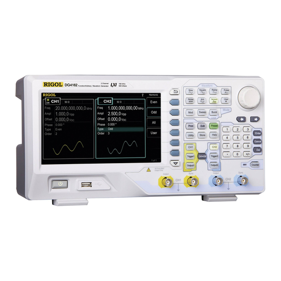
- Page 19 Content Conventions in this Manual: DG4000 series function/arbitrary waveform generator includes the following models. In this manual, DG4162 is taken as an example to illustrate DG4000 series function/arbitrary waveform generator. The introductions cover all the functions and performance of the other models.
-
Page 20: Table Of Contents
RIGOL Contents Contents Guaranty and Declaration ................I Safety Requirement .................. II General Safety Summary ................II Safety Terms and Symbols ................V Allgemeine Sicherheits Informationen ............VI Sicherheits Begriffe und Symbole ..............IX Care and Cleaning ..................X Environmental Considerations ..............XI DG4000 Series Overview .............. - Page 21 RIGOL Contents Align Phase ................... 2-10 To Set the Duty Cycle ................2-12 To Set the Symmetry ................2-13 To Set the Pulse Parameters ..............2-14 Pulse Width/Duty Cycle ..............2-14 Leading/Trailing Edge Time ............. 2-15 To Enable the Channel Output ..............2-16 Basic Waveform Output Example ............
- Page 22 RIGOL Contents To Select FM Modulation ..............5-6 To Select the Carrier Waveform Shape ..........5-6 To Set the Carrier Frequency ............. 5-6 To Select the Modulating Waveform Source ........5-7 To Set the Modulating Waveform Frequency ........5-8 To Set the Frequency Deviation ............5-8 PM ......................
- Page 23 RIGOL Contents BPSK ....................5-21 To Select BPSK Modulation .............. 5-21 To Select the Carrier Waveform Shape ..........5-21 To Set the Carrier Phase ..............5-21 To Select the Modulating Waveform Source ........5-22 To Set the BPSK Rate ..............5-22 To Set the BPSK Phase ..............
- Page 24 RIGOL Contents To Select the Carrier Waveform Shape ..........5-33 To Set the Pulse Width/Duty Cycle ........... 5-33 To Select the Modulating Waveform Source ........5-34 To Set the Modulating Waveform Frequency ........5-34 To Set the Pulse Width/Duty Cycle Deviation ........5-35 Chapter 6 Sweep ..................6-1...
- Page 25 RIGOL Contents Chapter 9 Store and Recall ..............9-1 Storage System Overview ................ 9-2 File Type ....................9-4 Browser Type ..................9-5 File Operation ..................9-6 Save ....................9-6 Read ....................9-8 Copy and Paste................. 9-9 Delete ....................9-9 New Directory ................9-10 Seamless Interconnection with Oscilloscope ..........
- Page 26 RIGOL Contents Channel Coupling ................10-22 Channel Copy ..................10-25 User-defined Waveform Key ..............10-26 To Restore the Preset Configuration ............10-28 To Use the External Power Amplifier (Option) ........10-33 To Lock the Keys ................. 10-37 Chapter 11 Remote Control ..............11-1 Remote Control via USB .................
-
Page 27: Chapter 1 Quick Start
RIGOL Chapter 1 Quick Start Chapter 1 Quick Start This chapter introduces the front panel, rear panel, user interface and parameter setting method as well as precautions when using the instrument for the first time. Subjects in this chapter: General Inspection ... -
Page 28: General Inspection
The consigner or carrier shall be liable for the damage to the instrument resulting from shipment. RIGOL would not be responsible for free maintenance/rework or replacement of the instrument. Inspect the instrument In case of any mechanical damage, missing parts, or failure in passing the electrical and mechanical tests, contact your RIGOL sales representative. -
Page 29: To Adjust The Supporting Legs
RIGOL Chapter 1 Quick Start To Adjust the Supporting Legs DG4000 allows users to unfold the supporting legs as stands to tilt the generator upwards for easier operation and observation during operation (as shown in Figure 1-1). Users can fold the supporting legs for easier storage or carry when the instrument is not in use (as shown in Figure 1-2). -
Page 30: Appearance And Dimensions
RIGOL Chapter 1 Quick Start Appearance and Dimensions The appearance and dimensions of DG4000 are as shown in Figure 1-3 and Figure 1-4 and the unit is mm. Figure 1-3 Front View DG4000 User's Guide... - Page 31 RIGOL Chapter 1 Quick Start 116.7 104.9 Figure 1-4 Side View DG4000 User's Guide...
-
Page 32: Front Panel
2. USB Host Support USB storage device, RIGOL digital oscilloscope and power amplifier. USB Storage Device: read the waveform files or state files in the USB ... - Page 33 RIGOL Chapter 1 Quick Start the USB storage device (a new folder named "Rigol" is created in the USB storage device automatically). Digital Oscilloscope: seamlessly interconnect with RIGOL DS1000E, DS6000, MSO/DS4000, MSO/DS2000 and MSO/DS1000Z series digital oscilloscopes; read and store the waveform displayed on the screen or stored in the internal memory of the oscilloscope and then rebuild the waveform losslessly.
- Page 34 RIGOL Chapter 1 Quick Start sweep or burst output manually (only when Output1 is enabled). Trigger2: in sweep or burst mode, it is used to trigger CH2 to generate a sweep or burst output manually (only when Output2 is enabled).
-
Page 35: To Set The Pulse Width/Duty Cycle
RIGOL Chapter 1 Quick Start the use method of the numeric keyboard, refer to the introduction in "Parameter Setting Method"). 12. Knob During parameter setting, it is used to increase (clockwise) or decrease (counterclockwise) the current highlighted number. It is used to select file storage location or select the file to be recalled when storing or recalling file. - Page 36 RIGOL Chapter 1 Quick Start Pulse----Pulse Generate a pulse waveform with frequency from 1μHz to 40MHz and variable pulse width and edge time. When this function is selected, the backlight of the key turns on. You can modify the "Freq/Period", "Ampl/HiLevel", "Offset/LoLevel", ...
- Page 37 RIGOL Chapter 1 Quick Start 15. Modes Mod----Modulation Generate the modulated waveforms. Provide various analog modulation and digital modulation modes and can generate AM, FM, PM, ASK, FSK, PSK, BPSK, QPSK, 3FSK, 4FSK, OSK or PWM modulated signal. Support internal and external modulations.
- Page 38 RIGOL Chapter 1 Quick Start Preset----Restore the Preset Values It is used to restore the instrument state to the factory default values or user-defined states (refer to the introduction in "To Restore the Preset Configuration"). Utility----Utility Functions and System Settings It is used to set the utility function parameters and the system parameters.
-
Page 39: Rear Panel
RIGOL Chapter 1 Quick Start Rear Panel The rear panel of DG4000 is as shown in the figure below. 4. 3. Figure 1-6 DG4000 Rear Panel AC Power Input This generator can accept AC power supply of 100-240V, 45-440Hz. Power Fuse: 250V, T2 A. - Page 40 RIGOL Chapter 1 Quick Start USB Device PictBridge printer or PC can be connected through this interface to print the screen image or control the generator remotely through PC software. 10MHz In/Out BNC female connector with 50Ω nominal impedance. The function of this connector is determined by the type of clock used by the generator.
- Page 41 RIGOL Chapter 1 Quick Start determined by the current working mode of CH2. Mod: If AM, FM, PM, PWM or OSK is enabled for CH2 and external modulation source is used, this connector accepts an external modulation signal. FSK: ...
-
Page 42: To Connect To Power
Figure 1-7 To Connect to Power CAUTION If the power fuse needs to be changed, please return the instrument back to our factory and the RIGOL authorized operator will change it for you. 1-16 DG4000 User's Guide... -
Page 43: To Replace The Fuse
RIGOL Chapter 1 Quick Start To Replace the Fuse To replace the fuse, please use the specified fuse and follow the steps below. Turn off the instrument, cut off the power supply and remove the power cord. Use a small straight screwdriver to prize out the fuse seat. -
Page 44: User Interface
RIGOL Chapter 1 Quick Start User Interface DG4000 user interface displays the parameters and waveforms of the two channels at the same time. The figure below is the interface when both CH1 and CH2 select Sine. Different contents will be displayed when different functions are enabled. - Page 45 RIGOL Chapter 1 Quick Start 3. Channel Status Display areas of CH1 and CH2. Indicate whether the corresponding channel is selected and turned on (ON/OFF).The area of the channel currently selected is highlighted and the on/off state of the channel currently turned on is "ON".
- Page 46 RIGOL Chapter 1 Quick Start currently will be highlighted and the lightspot above the number indicates current cursor location. 7. Offset Display the current waveform DC offset in each channel. Press the corresponding softkey Offset and use the numeric keyboard or direction keys and knob to modify this parameter.
-
Page 47: Parameter Setting Method
RIGOL Chapter 1 Quick Start Parameter Setting Method Users can use the numeric keyboard or knob and direction keys to set parameters. Numeric Keyboard The numeric keyboard consists of: Number Keys The 0 to 9 number keys are used to directly input the desired parameter value. -
Page 48: Direction Keys And Knob
RIGOL Chapter 1 Quick Start Direction keys and Knob Functions of the direction keys: During parameter input, use the direction keys to move the cursor to select the digit to be edited. During filename edit, use the direction keys to move the cursor. -
Page 49: To Use The Built-In Help
5. Generate an arbitrary waveform. 6. Generate a modulated waveform. 7. Generate a frequency Sweep. 8. Generate a Burst waveform. 9. Storage management. 10. Synchronize multiple Generators. 11. Seamlessly connected with the RIGOL DS. 12. Get technical support from RIGOL. 1-23 DG4000 User's Guide... -
Page 50: To Use The Security Lock
RIGOL Chapter 1 Quick Start To Use the Security Lock Use the security lock (option) to lock the generator at a fixed location. As shown in the figure below, align the lock with the lock hole and plug it into the lock hole vertically, turn the key clockwise to lock the instrument and then pull the key out. -
Page 51: Chapter 2 Basic Waveform Output
RIGOL Chapter 2 Basic Waveform Output Chapter 2 Basic Waveform Output DG4000 can output basic waveforms (including Sine, Square, Ramp, Pulse and Noise) from one of the channels separately or from the two channels at the same time. At start-up, the channel is configured as a sine waveform with 1kHz frequency and 5Vpp amplitude by default. -
Page 52: To Select The Channel
RIGOL Chapter 2 Basic Waveform Output To Select the Channel Users can configure DG4000 to output basic waveform from a single channel or from dual channels at the same time. Please select the desired channel before configuring waveform parameters. At start-up, CH1 is selected by default. -
Page 53: To Select Basic Waveform
RIGOL Chapter 2 Basic Waveform Output To Select Basic Waveform DG4000 can output 5 kinds of basic waveforms including Sine, Square, Ramp, Pulse and Noise. At start-up, Sine is selected by default. Sine Press Sine at the front panel to select sine waveform and the backlight of the button turns on. -
Page 54: To Set The Frequency
RIGOL Chapter 2 Basic Waveform Output To Set the Frequency Frequency is one of the most important parameters of basic waveforms. For different instrument models and different waveforms, the setting ranges of frequency are different. For detailed information, please refer to "Frequency Characteristics"... -
Page 55: To Set The Amplitude
RIGOL Chapter 2 Basic Waveform Output To Set the Amplitude The amplitude range is limited by the "Resistance" and "Freq/Period" settings. Please refer to "Output Characteristics" in "Specifications". The default value is 5Vpp. The amplitude displayed on the screen is the default value or the amplitude previously set. - Page 56 RIGOL Chapter 2 Basic Waveform Output Tips: Switch between Vpp and Vrms Vpp is the unit for the signal peak-peak value and Vrms is the unit for the signal effective value. The default unit of the instrument is Vpp. Users can quickly switch the current amplitude unit from the front panel.
- Page 57 RIGOL Chapter 2 Basic Waveform Output fulfill the following relation equation. Vrms × 10 lg( 0.001 Wherein, R denotes the output impedance of the channel and must be a specific value; therefore, when the output impedance is HighZ, dBm cannot be used.
-
Page 58: To Set The Dc Offset Voltage
RIGOL Chapter 2 Basic Waveform Output To Set the DC Offset Voltage The settable range of the DC offset voltage is limited by the "Resistance" and "Ampl/HiLevel" settings. Please refer to the "Output Characteristics" in "Specifications". The default value is 0V The DC offset voltage displayed on the screen is the default value or the offset previously set. -
Page 59: To Set The Start Phase
RIGOL Chapter 2 Basic Waveform Output To Set the Start Phase The setting range of start phase is from 0° to 360° and the default is 0°. The start phase displayed on the screen is the default value or the phase previously set. -
Page 60: Align Phase
RIGOL Chapter 2 Basic Waveform Output Align Phase DG4000 series dual-channel function/arbitrary waveform generator provides the align phase function. Press Align Phase and the instrument will re-configure the two channels to make them output with the specified frequency and phase. - Page 61 RIGOL Chapter 2 Basic Waveform Output Note: The Align Phase menu is grayed out and disabled when one of the two channels is in modulation mode. 2-11 DG4000 User's Guide...
-
Page 62: To Set The Duty Cycle
RIGOL Chapter 2 Basic Waveform Output To Set the Duty Cycle Duty Cycle is defined as the percentage that the high level takes up in the whole period as shown in the figure below. Duty Cycle=t/T*100% The duty cycle range is limited by the "Freq/Period" setting. Please refer to "Signal Characteristics"... -
Page 63: To Set The Symmetry
RIGOL Chapter 2 Basic Waveform Output To Set the Symmetry Symmetry is defined as the percentage that the rising period takes up in the whole period as shown in the figure below. This parameter is only available when ramp is selected. -
Page 64: To Set The Pulse Parameters
RIGOL Chapter 2 Basic Waveform Output To Set the Pulse Parameters To output a pulse, users need to set the "Width/Duty", "Leading" and "Trailing", in addition to the basic parameters (such as the frequency, amplitude, DC offset voltage, start phase, high level, low level and align phase) introduced above. -
Page 65: Leading/Trailing Edge Time
RIGOL Chapter 2 Basic Waveform Output The pulse width and pulse duty cycle are correlative. Once a parameter is changed, the other will be automatically changed. The pulse duty cycle is limited by the "Minimum Pulse Width" and "Pulse Period". -
Page 66: To Enable The Channel Output
RIGOL Chapter 2 Basic Waveform Output To Enable the Channel Output After configuring the parameters of the waveform selected, waveform output could be enabled. Note: Before enabling the channel, you can also configure the parameters (such as the resistance and polarity) related to the output of the corresponding channel through the channel setting menu (CH1Set or CH2Set) in Utility. -
Page 67: Basic Waveform Output Example
RIGOL Chapter 2 Basic Waveform Output Basic Waveform Output Example Configure the generator to output a pulse waveform with 1.5MHz frequency, 500mVpp amplitude, 5mV DC offset, 200ns pulse width, 75ns leading (rising) edge time and 100ns trailing (falling) edge time. - Page 68 RIGOL Chapter 2 Basic Waveform Output indicates current cursor location. Use the numeric keyboard to input the offset value "5" and select the unit "mV " from the pop-up menu. Press Width/Duty to highlight "Width". The lightspot above the number indicates current cursor location.
-
Page 69: Chapter 3 Arbitrary Waveform Output
RIGOL Chapter 3 Arbitrary Waveform Output Chapter 3 Arbitrary Waveform Output DG4000 can output the built-in waveforms and user-defined arbitrary waveforms from a single channel or from two channels at the same time. The 150 kinds of built-in waveforms are stored in the internal non-volatile memory. The user-defined arbitrary waveforms can contain 2 to 16384 (16k) data points, namely 2pts to 16kpts. -
Page 70: To Enable Arbitrary Waveform
RIGOL Chapter 3 Arbitrary Waveform Output To Enable Arbitrary Waveform Press Arb to enable arbitrary waveform function and open the operation menu of arbitrary waveform. 1. Freq/Period: set the "Freq/Period" of the arbitrary waveform. 2. Ampl/HiLevel: set the "Ampl/HiLevel" of the arbitrary waveform. - Page 71 RIGOL Chapter 3 Arbitrary Waveform Output Users can use User to quickly recall the built-in waveforms or waveforms stored in the non-volatile memory of the instrument. After you define the waveform to be recalled by this key, pressing this key will immediately recall the specified waveform.
-
Page 72: Point By Point Output Mode
RIGOL Chapter 3 Arbitrary Waveform Output Point By Point Output Mode DG4000 supports point by point output of arbitrary waveform. Press Arb to open the arbitrary waveform setting menu and press Point By Point to enable the point by point output mode of arbitrary waveform. -
Page 73: To Select Arbitrary Waveform
RIGOL Chapter 3 Arbitrary Waveform Output To Select Arbitrary Waveform DG4000 allows users to select arbitrary waveforms stored in internal or external memory for output. Press Arb Select Wform to select "Builtin", "Stored Wforms", "Volatile Wform" or "DC" for output. - Page 74 RIGOL Chapter 3 Arbitrary Waveform Output BandLimited Bandwidth-limited signal BlaseiWave Time-velocity curve of explosive vibration Butterworth Butterworth filter Chebyshev1 Chebyshev1 filter Chebyshev2 Chebyshev2 filter Combin Combination function CPulse C pulse CWPulse CW pulse DampedOsc Time-displacement curve of damped oscillation DualTone...
- Page 75 RIGOL Chapter 3 Arbitrary Waveform Output Pulseilogram Pulsilogram ResSpeed Speed curve of the respiration Medical LFPulse Waveform of the low frequency pulse electrotherapy Tens1 Waveform 1 of the nerve stimulation electrotherapy Tens2 Waveform 2 of the nerve stimulation electrotherapy Tens3...
- Page 76 RIGOL Chapter 3 Arbitrary Waveform Output Laguerre 4-times Laguerre polynomial Laplace Laplace distribution Legend 5-times Legend polynomial Logarithm function with the base 10 LogNormal Logarithmic Gaussian distribution Lorentz Lorentz function Maxwell Maxwell distribution Rayleigh Rayleigh distribution Versiera Versiera Weibull Weibull distribution...
- Page 77 RIGOL Chapter 3 Arbitrary Waveform Output ACotPro Protuberant arc cotangen ACotHCon Concave arc hyperbolic cotangent ACotHPro Protuberant arc hyperbolic cotangent ACscCon Concave arc cosecant ACscPro Protuberant arc cosecant ACscHCon Concave arc hyperbolic cosecant ACscHPro Protuberant arc hyperbolic cosecant ASecCon Concave arc secant...
-
Page 78: Stored Waveform
RIGOL Chapter 3 Arbitrary Waveform Output Stored Waveform Select the user-defined arbitrary waveforms stored in the internal non-volatile memory (C Disk) or external memory (D Disk). Press this softkey to enter the Store/Recall Interface and the Store key at the front panel is illuminated. Please select and read the desired arbitrary waveform file. -
Page 79: To Create An Arbitrary Waveform
RIGOL Chapter 3 Arbitrary Waveform Output To Create an Arbitrary Waveform Press Arb, use to open the 2/2 menu page, and then press Create Wform to open the arbitrary waveform creation interface. 1. Cycle Period Press this softkey and use the numeric keyboard or direction keys and knob to set the cycle period of the new waveform. - Page 80 RIGOL Chapter 3 Arbitrary Waveform Output 5. Interp Press this softkey to enable or disable the interpolation between the defined waveform points. Off: The waveform editor will hold a constant voltage level between two points and create a step waveform.
- Page 81 RIGOL Chapter 3 Arbitrary Waveform Output points and be lower than or equal to X2. Y1: Set the voltage of the start point in mV or V. The setting range of voltage is limited by the "HiLevel" and "LoLevel".
-
Page 82: Example: Edit Points
RIGOL Chapter 3 Arbitrary Waveform Output Example: Edit Points The following example introduces how to use "Edit Points" to create an arbitrary waveform fulfilling the following conditions. Parameter Value Cycle Period 12μs HiLevel LoLevel Interp Linear Point 1 0s, 0V Point 2 4μs, 4V... - Page 83 RIGOL Chapter 3 Arbitrary Waveform Output Press Point to define the first point (the time is 0 by default). Press Voltage, use the numeric keyboard to input "0" and select the unit "V" from the pop-up menu. Press Point again, use the numeric keyboard or knob to select point 2;...
-
Page 84: Example: Edit Block
RIGOL Chapter 3 Arbitrary Waveform Output Example: Edit Block The following example introduces how to use "Edit Block" to create an arbitrary waveform fulfilling the following conditions. Parameter Value Cycle Period 12μs HiLevel LoLevel Interp Linear X1Y1 2, 4V X2Y2... - Page 85 RIGOL Chapter 3 Arbitrary Waveform Output Press Execute to apply the setting defined in step 1). The waveform editor will automatically use straight lines to connect the start point (point 2, the level is 4 V) with the stop point (point 4, the level is -2 V) and automatically generate point 1 and point 3 to create a continuous waveform.
-
Page 86: To Edit Arbitrary Waveform
RIGOL Chapter 3 Arbitrary Waveform Output To Edit Arbitrary Waveform Arbitrary waveforms stored in internal non-volatile memory or external memory can be edited. Press Arb and use to open the 2/2 menu page, then press Edit Wform to open waveform editing menu. Users can also press Edit at the front panel to quickly open this menu. -
Page 87: Chapter 4 Harmonic Output
RIGOL Chapter 4 Harmonic Output Chapter 4 Harmonic Output DG4000 can be used as a harmonic generator to output harmonic with specified order, amplitude and phase. It is usually used in the test of harmonic detector device or harmonic filter device. This chapter introduces how to configure the generator to output harmonics. -
Page 88: Overview
RIGOL Chapter 4 Harmonic Output Overview According to Fourier transform, time domain waveform is the superposition of a series of sine waveforms as shown in the equation below: π ϕ π ϕ π ϕ sin( sin( sin( ..Generally, component with... -
Page 89: To Set The Harmonic Order
RIGOL Chapter 4 Harmonic Output To Set the Harmonic Order The highest order of harmonic output from DG4000 cannot be greater than this setting value. After entering the harmonic setting menu, press Order (at this point, "Order" on the screen is highlighted) and use the numeric keyboard or the direction keys and knob to input the harmonic order. -
Page 90: To Set The Harmonic Amplitude
RIGOL Chapter 4 Harmonic Output 16 bits binary data is used to represent the output status of the 16 orders of harmonics respectively, wherein, 1 represents enabling the output of the corresponding harmonic and 0 represents disabling the output of the corresponding harmonic. -
Page 91: To Set The Harmonic Phase
RIGOL Chapter 4 Harmonic Output To Set the Harmonic Phase After entering the harmonic setting menu, press Phase to set the phase of each order of harmonic. SN: press this softkey to select the sequence number of the harmonic to be set. -
Page 93: Chapter 5 Modulated Waveform Output
RIGOL Chapter 5 Modulated Waveform Output Chapter 5 Modulated Waveform Output DG4000 supports AM, FM, PM, ASK, FSK, 3FSK, 4FSK, PSK, BPSK, QPSK, PWM and OSK modulations. DG4000 can output modulated waveform from a single channel or from two channels at the same time. The modulated waveform consists of carrier waveform and modulating waveform. -
Page 94: To Select Am Modulation
RIGOL Chapter 5 Modulated Waveform Output Modulated waveform usually consists of carrier waveform and modulating waveform. For amplitude modulation (AM), the amplitude of the carrier waveform varies with the instantaneous voltage of the modulating waveform. To Select AM Modulation Press Mod Type AM to enable AM function. -
Page 95: To Select Modulating Waveform Source
RIGOL Chapter 5 Modulated Waveform Output After the carrier waveform is selected, you can press Freq/Period to highlight "Freq", and then use the numeric keyboard or direction keys and knob to input the desired frequency value. To Select Modulating Waveform Source DG4000 can receive modulating waveform from internal or external modulation source. -
Page 96: To Set Modulating Waveform Frequency
RIGOL Chapter 5 Modulated Waveform Output To Set Modulating Waveform Frequency When internal modulation source is selected, press AM_Freq to set the modulating waveform frequency. Input the desired frequency value using the numeric keyboard or direction keys and knob. -
Page 97: Double Sideband Suppressed Carrier
RIGOL Chapter 5 Modulated Waveform Output Double Sideband Suppressed Carrier DG4000 supports two kinds of amplitude modulation (normal amplitude modulation and Double Sideband Suppressed Carrier (DSB-SC) amplitude modulation). In normal amplitude modulation, the modulated waveform contains carrier components. As the carrier components do not carry information, the modulation efficiency is low. -
Page 98: To Select Fm Modulation
RIGOL Chapter 5 Modulated Waveform Output Modulated waveform consists of carrier waveform and modulating waveform. For frequency modulation (FM), the frequency of the carrier waveform varies with the instantaneous voltage of the modulating waveform. To Select FM Modulation Press Mod Type FM to enable FM function. -
Page 99: To Select The Modulating Waveform Source
RIGOL Chapter 5 Modulated Waveform Output After the carrier waveform is selected, you can press Freq/Period to highlight "Freq", and then use the numeric keyboard or direction keys and knob to input the desired frequency value. To Select the Modulating Waveform Source DG4000 can receive modulating waveform from internal or external modulation source. -
Page 100: To Set The Modulating Waveform Frequency
RIGOL Chapter 5 Modulated Waveform Output To Set the Modulating Waveform Frequency When internal modulation source is selected, press FM_Freq to set the modulating waveform frequency. Input the desired frequency value using the numeric keyboard or direction keys and knob. -
Page 101: To Select Pm Modulation
RIGOL Chapter 5 Modulated Waveform Output Modulated waveform consists of carrier waveform and modulating waveform. For phase modulation (PM), the phase of the carrier waveform varies with the instantaneous voltage of the modulating waveform. To Select PM Modulation Press Mod Type PM to enable PM function. -
Page 102: To Select The Modulating Waveform Source
RIGOL Chapter 5 Modulated Waveform Output After the carrier waveform is selected, you can press Freq/Period to highlight "Freq", and then use the numeric keyboard or direction keys and knob to input the desired frequency value. To Select the Modulating Waveform Source DG4000 can receive modulating waveform from internal or external modulation source. -
Page 103: To Set The Modulating Waveform Frequency
RIGOL Chapter 5 Modulated Waveform Output To Set the Modulating Waveform Frequency When internal modulation source is selected, press PM_Freq to set the modulating waveform frequency. Input the desired frequency value using the numeric keyboard or direction keys and knob. -
Page 104: Ask
RIGOL Chapter 5 Modulated Waveform Output When using ASK (Amplitude Shift Keying) modulation, you can configure the generator to "shift" its output amplitude between two preset amplitude values ("carrier amplitude" and "modulating amplitude"). The "shift" rate (ASK Rate) is determined by the internal signal level or signal level at the [Mod/FSK/Trig] connector at the rear panel. -
Page 105: To Select The Modulating Waveform Source
RIGOL Chapter 5 Modulated Waveform Output To Select the Modulating Waveform Source Press Mod Source to select "Int" or "Ext" modulating waveform source. 1. Internal Source When internal source is selected, the modulating waveform is set as a Square with 50% duty cycle, and the rate at which the output amplitude "shifts"... -
Page 106: To Set The Modulating Amplitude
RIGOL Chapter 5 Modulated Waveform Output To Set the Modulating Amplitude Press ModAmp to set the modulating amplitude. Use the numeric keyboard or direction keys and knob to input the desired amplitude value. The range of amplitude (HighZ) is from 0 to 10V and the default is 2V. -
Page 107: Fsk
RIGOL Chapter 5 Modulated Waveform Output When FSK (Frequency Shift Keying) modulation is selected, you can configure the generator to "shift" its output frequency between two preset frequencies ("carrier frequency" and "hop frequency"). The "shift" frequency (FSK Rate) is determined by the internal signal level or signal level at the [Mod/FSK/Trig] connector at the rear panel. -
Page 108: To Select The Modulating Waveform Source
RIGOL Chapter 5 Modulated Waveform Output Carrier Waveform Frequency Range Sine 1μHz to 160MHz Square 1μHz to 50MHz Ramp 1μHz to 4MHz Arbitrary Waveform 1μHz to 40MHz After the carrier waveform is selected, you can press Freq/Period to highlight "Freq", and then use the numeric keyboard or direction keys and knob to input the desired frequency value. -
Page 109: To Set The Fsk Rate
RIGOL Chapter 5 Modulated Waveform Output To Set the FSK Rate When internal source is selected, press FSK Rate to set the frequency at which the output frequency shifts between "carrier frequency" and "hop frequency". Use the numeric keyboard or direction keys and knob to input the desired ... -
Page 110: Psk
RIGOL Chapter 5 Modulated Waveform Output When PSK (Phase Shift Keying) modulation is selected, you can configure the generator to "shift" its output phase between two preset phase values ("carrier phase" and "modulating phase"). The "shift" frequency (PSK Rate) is determined by the internal signal level or signal level at the [Mod/FSK/Trig] connector at the rear panel. -
Page 111: To Select The Modulating Waveform Source
RIGOL Chapter 5 Modulated Waveform Output To Select the Modulating Waveform Source Press Mod Source to select "Int" or "Ext" modulating waveform source. 1. Internal Source When internal source is selected, the modulating waveform is set as a Square with 50% duty cycle, and the frequency at which the output phase shifts between "carrier phase"... -
Page 112: To Set The Psk Phase
RIGOL Chapter 5 Modulated Waveform Output To Set the PSK Phase PSK phase is the modulating phase. Press Phase to set the modulating phase. Use the numeric keyboard or direction keys and knob to input the desired phase value. -
Page 113: Bpsk
RIGOL Chapter 5 Modulated Waveform Output BPSK When BPSK (Binary Phase Shift Keying) is selected, you can configure the generator to "shift" its output phase between two preset phases ("carrier phase" and "modulating phase"). The "shift" frequency (BPSK rate) is determined by the internal signal level of the instrument. -
Page 114: To Select The Modulating Waveform Source
RIGOL Chapter 5 Modulated Waveform Output To Select the Modulating Waveform Source BPSK uses internal modulation source. Press Data Source to select PN15, PN21, 01 or 10and the default is PN15. Explanation: PN sequence (Pseudo-noise Sequence), a kind of periodic binary sequence, has the statistical characteristics similar to a random noise but can be produced and processed repeatedly. -
Page 115: To Set The Bpsk Phase
RIGOL Chapter 5 Modulated Waveform Output To Set the BPSK Phase BPSK phase is the modulating phase. Press Phase to set the modulating phase. Use the numeric keyboard or direction keys and knob to input the desired phase value. -
Page 116: Qpsk
RIGOL Chapter 5 Modulated Waveform Output QPSK When QPSK (Quadrature Phase Shift Keying) is selected, you can configure the generator to "shift" its output phase among four preset phases ("carrier phase" and three "modulating phases"). The "shift" frequency (QPSK rate) is determined by the internal signal level of the instrument. -
Page 117: To Select The Modulating Waveform Source
RIGOL Chapter 5 Modulated Waveform Output To Select the Modulating Waveform Source QPSK uses internal modulation source. Press Data Source to select PN15 or PN21 and the default is PN15. To Set the QPSK Rate QPSK uses internal modulation source. Press Rate to set the frequency at which the output phase shifts between "carrier phase"... -
Page 118: 3Fsk
RIGOL Chapter 5 Modulated Waveform Output 3FSK When 3FSK (3 Frequency Shift Keying) modulation is selected, you can configure the generator to "shift" its output frequency among three preset frequencies ("carrier frequency" and two "modulating frequencies"). The "shift" frequency (3FSK rate) is determined by the internal signal level of the instrument. -
Page 119: Modulation Source
RIGOL Chapter 5 Modulated Waveform Output Carrier Waveform Frequency Range Sine 1μHz to 160MHz Square 1μHz to 50MHz Ramp 1μHz to 4MHz Arbitrary Waveform 1μHz to 40MHz After the carrier waveform is selected, you can press Freq/Period to highlight "Freq", and then use the numeric keyboard or direction keys and knob to input the desired frequency value. -
Page 120: 4Fsk
RIGOL Chapter 5 Modulated Waveform Output 4FSK When 4FSK (4 Frequency Shift Keying) modulation is selected, you can configure the generator to "shift" its output frequency among four preset frequencies ("carrier frequency" and three "hop frequencies"). The "shift" frequency (4FSK rate) is determined by the internal signal level of the instrument. -
Page 121: Modulation Source
RIGOL Chapter 5 Modulated Waveform Output Carrier Waveform Frequency Range Sine 1μHz to 160MHz Square 1μHz to 50MHz Ramp 1μHz to 4MHz Arbitrary Waveform 1μHz to 40MHz After the carrier waveform is selected, you can press Freq/Period to highlight "Freq", and then use the numeric keyboard or direction keys and knob to input the desired frequency value. -
Page 122: Osk
RIGOL Chapter 5 Modulated Waveform Output When OSK (Oscillation Shift Keying) modulation is selected, users can configure the generator to output a sine signal with intermittent oscillation as shown in the figure below (the carrier waveform is 100Hz and the OSK rate is 10kHz). The... -
Page 123: To Select The Carrier Waveform Shape
RIGOL Chapter 5 Modulated Waveform Output To Select the Carrier Waveform Shape OSK carrier waveform can only be sine waveform. Press Sine at the front panel. To Set the Carrier Frequency After carrier waveform shape is selected, press Freq/Period to highlight "Freq"... -
Page 124: To Set The Osk Rate
RIGOL Chapter 5 Modulated Waveform Output To Set the OSK Rate When internal source is selected, press Rate to set the OSK rate. Use the numeric keyboard or direction keys and knob to input the desired frequency value. The frequency range is from 2mHz to 1MHz and the default is 1kHz. -
Page 125: Pwm
RIGOL Chapter 5 Modulated Waveform Output A PWM (Pulse Width Modulation) modulated waveform consists of carrier waveform and modulating waveform. The pulse width of the carrier waveform varies with the instantaneous voltage of the modulating waveform. To Select PWM Modulation PWM can only be used to modulate pulse. - Page 126 RIGOL Chapter 5 Modulated Waveform Output To Select the Modulating Waveform Source Press Mod Source to select "Int" or "Ext" modulating waveform source. 1. Internal Source When internal modulation source is selected, press Shape to select Sine, Square, Triangle, UpRamp, DnRamp, Noise or Arb as modulating waveform.
-
Page 127: To Set The Pulse Width/Duty Cycle Deviation
RIGOL Chapter 5 Modulated Waveform Output Use the numeric keyboard or direction keys and knob to input the desired frequency value. The frequency range is from 2mHz to 1MHz and the default is 100Hz. Note: When "Ext" modulation source is selected, this menu is grayed out and disabled. -
Page 129: Chapter 6 Sweep
RIGOL Chapter 6 Sweep Chapter 6 Sweep DG4000 can output sweep from a single channel or from dual channels at the same time. In sweep mode, the generator varies its output from the start frequency to end frequency within the specified sweep time. DG4000 supports... -
Page 130: To Enable Frequency Sweep
RIGOL Chapter 6 Sweep To Enable Frequency Sweep Press Sweep at the front panel to enable the sweep function (the backlight of the key goes on), and Mod or Burst function will be automatically disabled (if currently enabled). The instrument will generate the sweep waveform from the corresponding channel (if currently turned on) according to the current configuration. -
Page 131: Center Frequency And Frequency Span
RIGOL Chapter 6 Sweep Center Frequency and Frequency Span You can also set the frequency boundaries of frequency sweep through center frequency and frequency span. Center Frequency = (|Start Frequency + End Frequency|) / 2 Frequency Span = End Frequency – Start Frequency ... -
Page 132: Sweep Type
RIGOL Chapter 6 Sweep If the center frequency is 550Hz, the range of the frequency span is: ±2 × (550Hz – 1μHz) = ±1.099999998kHz; if the center frequency is 155MHz, the range of the frequency span range is: ±2 × (160MHz – 155MHz) = ±10MHz. -
Page 133: Log Sweep
RIGOL Chapter 6 Sweep Figure 6-1 Linear Sweep Log Sweep The output frequency of the instrument varies in a logarithmic fashion, that is, the output frequency changes in the way of "octave per second" or "decade per second". The change is controlled by "Start Frequency", "End Frequency" and "Sweep Time". -
Page 134: Step Sweep
RIGOL Chapter 6 Sweep start Wherein, t is the time from the start of the sweep and its range is from 0 to sweep is the instantaneous frequency currently output. current When Sweep is enabled, press Type to select "Log". An exponential function curve is displayed on the waveform on the screen, indicating that the output frequency changes in a logarithmic mode. -
Page 135: Sweep Time
RIGOL Chapter 6 Sweep determined by "Sweep Time" and "Step Number". When Sweep is enabled, press Type to select "Step". A step waveform is displayed on the waveform on the screen, indicating that the output frequency changes in "steps". At this point, press to open the 2/2 menu page. -
Page 136: Return Time
RIGOL Chapter 6 Sweep Return Time The generator will always sweep from the "Start" frequency to the "Stop" frequency and stay within the "Stop Hold" time. Return time describes the time needed for the output signal to return to the "Start" frequency from the "Stop"... -
Page 137: Start Hold
RIGOL Chapter 6 Sweep Start Hold Start hold is the period of time that the output signal outputs with the "Start" frequency after the sweep starts. After the start hold time expires, the generator will output with varying frequency in the current sweep type. -
Page 138: Sweep Trigger Source
RIGOL Chapter 6 Sweep Sweep Trigger Source The sweep trigger source could be internal, external or manual. The generator will generate a sweep output when a trigger signal is received and then wait for the next trigger. When Sweep is enabled, use to open the 2/2 menu page and press Source to select "Int", "Ext"... -
Page 139: Trigger Output Edge
RIGOL Chapter 6 Sweep Trigger Output Edge In sweep mode, when "Int" or "Manual" trigger source is selected, the generator will output a TTL compatible signal with specified edge from the [Mod/FSK/Trig] connector at the rear panel. [Mod/FSK/Trig] Internal Trigger: the generator outputs a Square waveform with 50% duty ... -
Page 141: Chapter 7 Burst
RIGOL Chapter 7 Burst Chapter 7 Burst DG4000 can output waveform with specified number of cycles (called Burst) from a single channel or from dual channels at the same time. DG4000 supports control of burst output by internal, manual or external trigger source; supports three kinds of burst types including N cycle, infinite and gated. -
Page 142: To Enable Burst Mode
RIGOL Chapter 7 Burst To Enable Burst Mode Press Burst at the front panel to enable Burst function (the backlight of the key goes on), and Mod or Sweep function will be automatically disabled (if currently enabled). The generator will output burst waveform from the corresponding channel (if currently turned on) according to the current configuration. -
Page 143: Infinite Burst
RIGOL Chapter 7 Burst When Burst is enabled, press Type to select "N Cycle". The parameter "Cycles" on the screen is highlighted and could be edited. At this point, use the numeric keyboard or the direction keys and knob to change the number of cycles; the default is 1 and the settable range is from 1 to 1 000 000 (external trigger or manual trigger) or 1 to 500 000 (internal trigger). -
Page 144: Gated Burst
RIGOL Chapter 7 Burst (manual trigger). When Burst is enabled, press Type to select "Infinite". A schematic diagram of infinite cycle pulse will be displayed on the screen. Figure 7-2 Infinite Burst Gated Burst In Gated Mode, the generator controls the waveform output according to the external signal level from the [Mod/FSK/Trig] connector at the rear panel. - Page 145 RIGOL Chapter 7 Burst then stops and holds on the voltage level corresponding to the initial burst phase of the selected waveform. For Noise waveform, the output will stop immediately once the gated signal becomes "False". Gated Burst could only be triggered by "Ext" trigger source. Users can also set the "Start Phase".
-
Page 146: Burst Phase
RIGOL Chapter 7 Burst Burst Phase Burst phase is defined as the phase of the start point of the burst. When Burst is enabled, press Start Phase and then use the numeric keyboard or knob to input the desired phase. The default value is 0° and the settable range is from 0°... -
Page 147: Burst Delay
RIGOL Chapter 7 Burst Burst Delay Burst delay is only available for N cycle and infinite burst mode. It is defined as the time from when the generator receives the trigger signal to starts to output the N Cycle (or Infinite) burst. -
Page 148: Trigger Output Edge
RIGOL Chapter 7 Burst output terminal of trigger signal. [Mod/FSK/Trig] Manual Trigger When manual trigger is selected, the generator can output N cycle or infinite burst. A burst will be generated from the corresponding channel (if currently turned on) once you press Trigger1 or Trigger2 at the front panel. If the corresponding channel is not turned on, the trigger will be ignored. - Page 149 RIGOL Chapter 7 Burst width from the [Mod/FSK/Trig] connector at the start of burst. In external trigger, the [Mod/FSK/Trig] connector is used as the input terminal of external trigger signal and has no trigger output. When "Int" or "Manual" trigger is selected, press TrigOut to specify the edge of the trigger output signal and the default is "Off".
-
Page 151: Chapter 8 Counter
RIGOL Chapter 8 Counter Chapter 8 Counter DG4000 provides a 7 digits/s counter which can measure various parameters (such as frequency, period, duty cycle, positive pulse width and negative pulse width) of external input signal and support statistic of measurement results. When the... -
Page 152: To Enable The Counter
RIGOL Chapter 8 Counter To Enable the Counter Press Counter at the front panel (the backlight of the key turns on) to enable counter function and enter counter setting interface as shown in the figure below. If the counter is currently turned on and the screen displays the counter interface, pressing Counter will disable the counter function. -
Page 153: To Set The Counter
RIGOL Chapter 8 Counter To Set the Counter You need to configure appropriate parameters for the counter. TrigSens Set the trigger sensitivity of the counter. The default is 50% and the range available is from 0% to 100%. Press TrigSens. Use the numeric keyboard to input the desired value and select the unit "%"... - Page 154 RIGOL Chapter 8 Counter measurement. Press HFSuppre to enable or disable the high-frequency suppression function. Note: Enable the high-frequency suppression function when low-frequency signal with lower than 1kHz frequency is measured to filter out the high-frequency noise interference; disable the high-frequency suppression function when high-frequency signal with greater than 1kHz frequency is measured.
- Page 155 RIGOL Chapter 8 Counter 11. State Press State to set the running status of the counter to "Run" or "Stop". When you press Counter at the front panel, the counter enters the "Run" state automatically and measures the input signal continuously according to the current configuration.
-
Page 156: Statistic
RIGOL Chapter 8 Counter Statistic When the statistic function is turned on, the instrument calculates the maximum, minimum, average and standard deviation of the measurement values automatically and displays the variation tendency of the measurement values in "Digital" or "Curve" mode. Press Statist Set to enter the statistic function setting menu. - Page 157 RIGOL Chapter 8 Counter unit from the pop-up unit menu or use the direction keys and knob to modify the current value. Press Type to set the statistic type of the statistic parameter. Cyclic: restart the statistic operation when the number of statistic operations reaches the specified statistic length.
- Page 158 RIGOL Chapter 8 Counter Figure 8-3 Curve Display Interface of the Statistic Results Note: When the statistic function is turned off, Display is grayed out and disabled. Clear the statistic results When the statistic function is turned on, press Clear and the signal generator will clear the current statistic results.
-
Page 159: Chapter 9 Store And Recall
RIGOL Chapter 9 Store and Recall Chapter 9 Store and Recall DG4000 allows users to store the current instrument state and user-defined arbitrary waveform data in the internal or external memory and recall them when needed. Subjects in this chapter: Storage System Overview ... -
Page 160: Storage System Overview
RIGOL Chapter 9 Store and Recall Storage System Overview DG4000 allows users to store the current instrument state or user-defined arbitrary waveform data in the internal or external memory and recall them when needed. DG4000 provides an internal non-volatile memory (C Disk) and an external memory (D Disk). - Page 161 RIGOL Chapter 9 Store and Recall Note: DG4000 can only identify filenames consist of Chinese characters, English letters, number and underscore. If other characters are used to name the file or folder, the name might be displayed in the store and recall interface abnormally.
-
Page 162: File Type
RIGOL Chapter 9 Store and Recall File Type Press Store File Type to select the desired file type. The file types available include State File, Arb File, Txt File, Csv File and All File. 1. State File Store the instrument state in the internal or external memory in "*.RSF" format. -
Page 163: Browser Type
RIGOL Chapter 9 Store and Recall 5. All File Display all the files and folders in the currently selected directory. When this menu is selected, the store function is not available. Browser Type Press Store Browser to switch between "Dir" and "File". Use the knob to select the desired directory or file. -
Page 164: File Operation
RIGOL Chapter 9 Store and Recall File Operation When "File" is select as the browser type, users can perform a series of operations on files including Save, Read, Copy, Paste, Delete and New Directory. Save Select the file type Follow the introduction in "File Type" to select the type of the file to be saved. - Page 165 RIGOL Chapter 9 Store and Recall Input the filename Press IME to select "Chinese" or "English". The length of the file or folder name is limited within 27 characters. English Input (include number input): Press +/- on the numeric keyboard to switch between uppercase and lowercase.
-
Page 166: Read
RIGOL Chapter 9 Store and Recall pinyin of a Chinese character, use the numeric keyboard to select the No. of the desired Chinese character (if the desired Chinese character is not currently displayed, use the direction key to open the next page) and the Chinese character selected would be displayed in the "Filename Input... -
Page 167: Copy And Paste
RIGOL Chapter 9 Store and Recall Copy and Paste DG4000 allows users to copy the state file or arbitrary waveform file stored in the internal memory (C disk) to the external memory (USB storage device). Select the file to be copied Set Browser as "Dir"... -
Page 168: New Directory
RIGOL Chapter 9 Store and Recall New Directory DG4000 allows users to create new folders in the external memory (USB storage device). Please make sure that a USB storage device is inserted and identified by the instrument. 1. Select the memory In the store and recall interface, set Browser as "Dir"... -
Page 169: Seamless Interconnection With Oscilloscope
RIGOL Chapter 9 Store and Recall Seamless Interconnection with Oscilloscope DG4000 can be seamlessly interconnected with RIGOL DS1000E, DS6000, MSO/DS4000, MSO/DS2000 and MSO/DS1000Z series digital oscilloscopes to rebuild and output the waveform data sampled by the oscilloscope losslessly. The connection methods between the instruments are as shown in the figure below. - Page 170 RIGOL Chapter 9 Store and Recall waveform (Arb) mode (if DG4000 is not currently in the arbitrary waveform mode) and read the waveform displayed on the screen (when DataSel is set to "Screen") or stored in the internal memory (when DataSel is set to "Ram") of oscilloscope 1 to its internal volatile memory.
-
Page 171: Chapter 10 Utility Functions And System Settings
RIGOL Chapter 10 Utility Functions and System Settings Chapter 10 Utility Functions and System Settings DG4000 allows users to configure the parameters of dual channels, configure remote interfaces and set system parameters. Subjects in this chapter: Overview Channel Setting ... -
Page 172: Overview
RIGOL Chapter 10 Utility Functions and System Settings Overview Press Utility at the front panel to open the operation interface as shown in the figure below. This interface displays the current channel output configuration, channel coupling configuration and system parameters. -
Page 173: Channel Setting
RIGOL Chapter 10 Utility Functions and System Settings Channel Setting This section takes CH1 for example to illustrate how to set the channel. The setting method for CH2 is quite the same. Sync DG4000 could output the sync signals of basic waveforms (except Noise), arbitrary waveforms (except DC), Harmonics, Sweep signal, Burst signal and modulated signal from a single channel or two channels at the same time. -
Page 174: Sync Polarity
RIGOL Chapter 10 Utility Functions and System Settings with 50% duty cycle. For ASK, FSK and PSK, in external modulation mode, there is no sync signal output. For OSK, the sync signal is a square with 50% duty cycle and takes OSK ... -
Page 175: Sync Mode
RIGOL Chapter 10 Utility Functions and System Settings Sync Mode Set the output mode of the sync signal on the [Sync] connector at the front panel to normal or carrier. Press Utility CH1Set SyncMode to select "Normal" or "Carrier". -
Page 176: Impedance
RIGOL Chapter 10 Utility Functions and System Settings Impedance The impedance setting is applicable to output amplitude and DC offset voltage. DG4000 has a 50Ω fixed serial output impedance for the [Output1] connector at the front panel. If the actual load does not match the specified value, the voltage level displayed would not match the voltage level of the component under test. -
Page 177: Noise Superimposition
RIGOL Chapter 10 Utility Functions and System Settings Noise Superimposition DG4000 supports to superimpose a gauss noise onto its output signal. This function is called noise superimposition. The signal superimposed with noise can be used to test the anti-noise capability of the instrument. -
Page 178: To Set The System Language
RIGOL Chapter 10 Utility Functions and System Settings instrument is not powered off, the two channels will always be in the align phase state (at this point, the align phase state of the two channels will not be affected when you turn on or off the output of CH1 (or CH2)) after an align phase operation is executed when the output of CH2 (or CH1) is not turned off. -
Page 179: To Configure The Remote Interface
RIGOL Chapter 10 Utility Functions and System Settings To Configure the Remote Interface DG4000 is configured with USB and LAN interfaces and supports users to configure the interface parameters for remote communication. Press Utility I/O Config to open the I/O setting menu and set the LAN interface parameters for remote communication or select the type of device connected to the USB interface. - Page 180 RIGOL Chapter 10 Utility Functions and System Settings Network Status Different prompt messages will be provided by the generator based on the current network status. Configured Disconnect Initializing IP Conflict DHCP Failed MAC Address MAC (Media Access Control) address, also called hardware address, is used for defining the position of the network device.
- Page 181 RIGOL Chapter 10 Utility Functions and System Settings IP Configure Mode IP configure mode could be DHCP, Auto IP or Manual. If the network is disconnected currently, there will be nothing to display behind "IP Configure Mode:". In different IP configuration modes, the configuration modes of network parameters (such as IP address) are different.
- Page 182 RIGOL Chapter 10 Utility Functions and System Settings Tips If all the three IP configuration modes are "On", the priority of parameters configuration from high to low is "DHCP", "AutoIP" and "ManualIP". The three IP configuration modes cannot be set as "Off" at the same time.
- Page 183 RIGOL Chapter 10 Utility Functions and System Settings To Set the Domain Name Server (DNS) In ManualIP mode, the DNS could be manually set. The DNS format is nnn.nnn.nnn.nnn, where the first nnn ranges from 1 to 223 (except 127) and the other three nnn range from 0 to 255. It is recommended that users acquire an available DNS address from their network administrator.
-
Page 184: To Set The Usb Device Type
RIGOL Chapter 10 Utility Functions and System Settings To Set the USB Device Type The USB Device interface at DG4000 rear panel could be connected with PC or PictBridge printer to control the instrument remotely or to print the contents displayed on the screen. -
Page 185: System Setting
RIGOL Chapter 10 Utility Functions and System Settings System Setting Number Format You can set the display formats of the decimal point and thousands separator in number parameters. This setting is stored in non-volatile memory. Press Utility System Number Format to enter the number format setting interface. -
Page 186: Power On Setting
RIGOL Chapter 10 Utility Functions and System Settings Power On Setting Set the configuration to be used when the instrument is powered on the next time to "Default" or "Last". The default setting is "Default". Last: include all the system parameters, except output configuration, clock ... -
Page 187: Brightness
RIGOL Chapter 10 Utility Functions and System Settings source is detected, the prompt message "Not detect a valid external clock!" would be displayed and the clock source would be switched to "Int". Users can also synchronize two or more instruments by setting the clock source. -
Page 188: Beeper
RIGOL Chapter 10 Utility Functions and System Settings Beeper When the beeper in DG4000 is turned, the beeper sounds when users operate the front panel or when an error occurs during remote control. Press Utility System Beeper to select "On" or "Off" and the default is "On". -
Page 189: Print
Format to set to store the screen picture in "Bmp" or "Jpeg" format. Execute the print operation Press Print at the front panel and the generator will print the screen via the PictBridge printer or store the screen in the folder named as "Rigol" (if this 10-19 DG4000 User's Guide... - Page 190 RIGOL Chapter 10 Utility Functions and System Settings folder does not currently exist, it will be created automatically) in the USB storage device in picture format according to the preset configuration. Note: If no PictBridge printer is currently connected to the generator or no USB storage device is detected, the print operation would fail and the prompt message "PictBridge equipment is not connected."...
-
Page 191: Test/Cal
This menu is available only when Secure is set to "Off". Pressing this softkey can restore the calibration values to their factory default values. Note: Manual calibration by users is not recommended. If calibration is required, please contact RIGOL. 10-21 DG4000 User's Guide... -
Page 192: Channel Coupling
RIGOL Chapter 10 Utility Functions and System Settings Channel Coupling DG4000 supports to enable frequency, phase and amplitude couplings separately or at the same time. When coupling is enabled, set CH1 or CH2 as the "base" channel and set the frequency, phase or amplitude deviation of the two channels. - Page 193 RIGOL Chapter 10 Utility Functions and System Settings the coupling base respectively as shown in the figure below, indicating that the generator is in frequency, phase and amplitude couplings. Change the frequency, phase and amplitude of CH2 to 100Hz, 0° and 1Vpp respectively and the parameters of CH1 will change to 200Hz, 10°...
- Page 194 RIGOL Chapter 10 Utility Functions and System Settings Channel coupling and channel copy are mutually exclusive. The prompt message "Channel copy not allowed in Coupling mode." would be displayed if users execute channel copy operation (press CH1 CH2 at the front panel) when channel coupling is enabled.
-
Page 195: Channel Copy
RIGOL Chapter 10 Utility Functions and System Settings Channel Copy DG4000 supports state copy or waveform copy function between its two channels, namely copy the state (parameters and output configuration) or arbitrary waveform parameters of one channel to the other or swap the states of the two channels. -
Page 196: User-Defined Waveform Key
RIGOL Chapter 10 Utility Functions and System Settings User-defined Waveform Key User at the front panel of DG4000 provides a shortcut for users. You can define this shortcut key as the desired built-in waveform or arbitrary waveform stored in the internal memory of the instrument. You can recall the desired waveform under any operation interface once you press this shortcut key. - Page 197 RIGOL Chapter 10 Utility Functions and System Settings modify the waveform parameters. Figure 10-6 Press User to Quickly Recall the Waveform 10-27 DG4000 User's Guide...
-
Page 198: To Restore The Preset Configuration
RIGOL Chapter 10 Utility Functions and System Settings To Restore the Preset Configuration Restore the generator to its factory default state or states stored. Factory Default State: the parameter values are as shown in the table below. Note that items marked with "*" will not be affected by the preset operation. - Page 199 RIGOL Chapter 10 Utility Functions and System Settings Ramp Waveform Symmetry Pulse Duty Cycle Pulse Width 500μs Pulse Leading Edge 1.9531μs Pulse Trailing Edge 1.9531μs Arb Waveform Built-in Arbitrary Waveform Sinc Point By Point Output Harmonic Order Type Even Amplitude 1.264,7Vpp...
- Page 200 RIGOL Chapter 10 Utility Functions and System Settings Modulating Waveform Sine Modulating Frequency 100Hz Width Deviation 200μs Duty Cycle Deviation ASK Modulation Modulation Source ASK Rate 100Hz Modulating Amplitude 2Vpp ASK Polarity FSK Modulation Modulation Source FSK Rate 100Hz Hop Frequency...
- Page 201 RIGOL Chapter 10 Utility Functions and System Settings Key Frequency 100Hz Hop Frequency 1 100Hz Hop Frequency 2 100Hz 4FSK Modulation Key Frequency 100Hz Hop Frequency 1 100Hz Hop Frequency 2 100Hz Hop Frequency 3 100Hz OSK Modulation Modulation Source...
- Page 202 RIGOL Chapter 10 Utility Functions and System Settings Gated Polarity Trigger Source Trigger Output Trigger Input Leading Trigger Period 10ms System Parameter DHCP Auto IP Manual IP Beeper Power On Setting Default Screen Saver Clock Source Internal Decimal Point Thousand Separator...
-
Page 203: To Use The External Power Amplifier (Option)
PC via the USB interface. Users can set the gain (X1 or X10), polarity (normal or invert), output offset and output switch of the amplifier via RIGOL DG series signal generator or PC software. Provide up to 50kΩ input impedance. -
Page 204: Status Indicators
RIGOL Chapter 10 Utility Functions and System Settings Front Panel: Status Indicator Signal Output Terminal Signal Input Terminal Status Indicators Power: illuminated in red indicating that the power is successfully connected. Output: illuminated in green indicating that the output is turned on. - Page 205 RIGOL Chapter 10 Utility Functions and System Settings Rear Panel: USB Device Power Input Terminal Fan Cooling Apertures CAUTION Do not use other type of adapter to provide power for PA1011; otherwise, the instrument performance might be affected or the instrument might be permanently damaged.
- Page 206 RIGOL Chapter 10 Utility Functions and System Settings Connect DG4000 and PA1011: Output BNC Cable Input PA1011 DG4000 USB Host USB Cable USB Device Output After DG4000 and PA1011 are successfully connected as shown in the figure above, press Utility PA Set to open the parameter setting interface of the power amplifier.
-
Page 207: To Lock The Keys
RIGOL Chapter 10 Utility Functions and System Settings internal memory. When the power amplifier is turned "On" the next time, it will automatically recall the last working state stored. For the technical specifications of PA1011, refer to "Appendix B: Power Amplifier Specifications". - Page 208 RIGOL Chapter 10 Utility Functions and System Settings LEFT|RIGHT|KNOB /*Direction keys and knob*/ NUM0|NUM1|NUM2|NUM3|NUM4|NUM5| /*Numeric keyboard*/ NUM6|NUM7|NUM8|NUM9|DOT|SIGN| ENTER|CANCEL|DELETE COUNTER /*Frequency counter*/ /*All the keys (except the power key) and knob at the front panel*/ {ON|OFF|0|1} is used to lock or unlock the keys and can be ON|1 (locking the specified key) or OFF|0 (unlocking the specified key).
- Page 209 RIGOL Chapter 10 Utility Functions and System Settings The filename suffix must be ".scpi". The file content requirements: The first row: the command used to lock or unlock the specified key. The second row: empty row (cannot be omitted).
-
Page 211: Chapter 11 Remote Control
Use PC software Users can use the PC software to send commands to remotely control DG4000. Ultra Sigma of RIGOL is recommended. You can download the latest version of Ultra Sigma from RIGOL official website (www.rigol.com). DG4000 can communicate with PC through USB and LAN instrument buses. This chapter will give a detailed introduction of how to use Ultra Sigma to control DG4000 remotely through various interfaces. -
Page 212: Remote Control Via Usb
RIGOL Chapter 11 Remote Control Remote Control via USB Connect the device Connect the signal generator (USB Device interface) with your PC using a USB cable. Install the USB driver This signal generator is a USBTMC device. After you connect the signal generator to the PC and turn on the signal generator for the first time (the signal generator is automatically configured to USB interface;... - Page 213 RIGOL Chapter 11 Remote Control 11-3 DG4000 User's Guide...
- Page 214 PC via the USB interface. You can also click to search for the resources. View the device resource The resource found will appear under the "RIGOL Online Resource" directory and the model number and USB interface information of the instrument will 11-4 DG4000 User's Guide...
- Page 215 For example, DG4162 (USB0::0x1AB1::0x0641::DG410520023::INSTR). Control the instrument remotely Right click the resource name "DG4162 (USB0::0x1AB1::0x0641::DG410520023::INSTR)" to select "SCPI Panel Control" to open the remote command control panel through which you can send commands and read data. 11-5...
-
Page 216: Remote Control Via Lan
View the device resource The resource found will appear under the "RIGOL Online Resource" directory. For example, DG4162 (TCPIP::172.16.3.190::INSTR). Control the instrument remotely Right click the resource name "DG4162 (TCPIP::172.16.3.190::INSTR)" to select "SCPI Panel Control"... - Page 217 RIGOL Chapter 11 Remote Control Load LXI webpage As this signal generator conforms to LXI Core 2011 Device instrument standard, you can load the LXI webpage through Ultra Sigma (right-click the instrument resource name and select "LXI-Web"). Various important information about the signal generator (include the model number, manufacturer, serial number, description, MAC address and IP address) will be displayed on the webpage.
-
Page 219: Chapter 12 Troubleshooting
This chapter lists the commonly encountered failures of DG4000 and their solutions. When you encounter those problems, please solve them following the corresponding steps. If the problem persists, please contact RIGOL and provide your device information (Utility System System Info). - Page 220 (5) After finishing the above inspections, press Utility System PowerOn to select "Last" and then restart the instrument. (6) If it still does not work correctly, please contact RIGOL. The USB storage device cannot be recognized: (1) Check whether the USB storage device can work normally when connected to other instruments or PC.
- Page 221 RIGOL Chapter 12 Troubleshooting 8) Check whether the test devices used are under the working conditions specified in the corresponding manual. 9) Check whether all the connections are tight. 10) Check whether any cable has internal damage. 11) Make sure that the operations conform to the settings and processes specified by the performance verification guide.
-
Page 223: Chapter 13 Specifications
The generator has been working continuously for at least 30 minutes under the specified temperature (18℃ to 28℃). All the specifications are guaranteed unless those marked with "typical". Model DG4202 DG4162 DG4102 DG4062 Channel Maximum 200MHz 160MHz 100MHz... - Page 224 RIGOL Chapter 13 Specifications Sine Wave Spectrum Purity Harmonic Distortion Typical (0dBm) DC-1MHz: <-60dBc 1MHz-10MHz: <-55dBc 10MHz-100MHz: <-50dBc 100MHz-160MHz: <-40dBc Total Harmonic <0.1% (10Hz-20kHz,0dBm) Distortion Spurious Typical (0dBm) (non-harmonic) ≤10MHz <-65dBc >10MHz <-65dBc+6dB/octave Phase Noise Typical (0dBm, 10kHz deviation) 10MHz: ≤-115dBc/Hz...
- Page 225 RIGOL Chapter 13 Specifications Overshoot Typical (1Vpp) <3% Jitter (rms) Typical (1Vpp) 2ppm+500ps ≤5MHz >5MHz 500ps Waveform Length 16k points Vertical Resolution 14bits Sample Rate 500MSa/s Minimum Rise/Fall Typical (1Vpp) Time <5ns Jitter (rms) Typical (1Vpp) 2ppm+500ps ≤5MHz >5MHz 500ps...
- Page 226 RIGOL Chapter 13 Specifications Sine wave, ±0.1dB ±0.1dB ±0.1dB ±0.1dB 500mVpp, 50Ω) ≤60MHz: ≤60MHz: ≤60MHz: ≤60MHz: ±0.2dB ±0.2dB ±0.2dB ±0.2dB ≤100MHz: ≤100MHz: ≤100MHz: ±0.4dB ±0.4dB ±0.4dB ≤160MHz: ≤160MHz: ±0.8dB ±0.8dB ≤200MHz: ±1dB Units Vpp, Vrms, dBm Resolution 1mV or 3bits Offset (into 50 Ω)
- Page 227 RIGOL Chapter 13 Specifications Carrier Waveform Sine, Square, Ramp, Arb (except DC) Source Internal/External Modulating Sine, Square, Ramp, Noise, Arb Waveform Phase Deviation 0° to 360° Modulating 2mHz to 50KHz Frequency Carrier Waveform Sine, Square, Ramp, Arb (except DC) Source...
- Page 228 RIGOL Chapter 13 Specifications Waveform Key Frequency 2mHz to 1MHz BPSK Carrier Waveform Sine, Square, Ramp, Arb (except DC) Source Internal Modulating Sine, Square, Ramp, Noise, Arb Waveform Key Frequency 2mHz to 1MHz QPSK Carrier Waveform Sine, Square, Ramp, Arb (except DC)
- Page 229 RIGOL Chapter 13 Specifications 60MHz Burst Count 1 to 1 000 000 or Infinite Start/Stop Phase 0° to 360° Internal Period 2μs to 500s Gated Source External Trigger Trigger Source Internal, External or Manual Trigger Delay 0ns to 85s Sweep Characteristics...
- Page 230 RIGOL Chapter 13 Specifications Pulse Width and Duty Cycle Measurement 50mVRMS to Frequency/Amplitud 1μHz to 25MHz DC Coupling e Range ±2.5Vac+dc Input Minimum ≥20ns Pulse Width Attenuation: Resolution "closed" Duty Cycle Range (Display) 0% to 100% Input Characteristics ±7Vac+dc (Attenuation:...
- Page 231 RIGOL Chapter 13 Specifications Slope Rising or falling (selectable) Pulse Width >50ns Latency Sweep: <100ns (typical) Burst: <300ns (typical) Trigger Output Level TTL-compatible Pulse Width >60ns (typical) Maximum Rate 1MHz Clock Reference Phase Offset Range 0° to 360° Resolution 0.03°...
- Page 232 RIGOL Chapter 13 Specifications Power Power Voltage 100V to 240V (45Hz to 440Hz) Power Consumption Less than 50W Fuse 250V, T2A Display Type 7-inch TFT LCD Resolution 800 Horizontal × RGB × 480 Vertical Resolution Color 16M color Environment Operating: 10℃ to 40℃...
-
Page 233: Chapter 14 Appendix
Rack Mount Kit RM-DG4000 Optional 10W Power Amplifier Module PA1011 Accessories DG4 PC Software (Advanced Function Ultra Station-adv Software) Soft Carrying Bag BAG-G1 Note: All the options or accessories can be ordered from you local RIGOL office. 14-1 DG4000 User's Guide... -
Page 234: Appendix B: Power Amplifier Specifications
RIGOL Chapter 14 Appendix Appendix B: Power Amplifier Specifications Unless otherwise noted, all the specifications can be guaranteed under the following two conditions. The instrument has been working continuously for at least 30 minutes under the specified operation temperature. - Page 235 RIGOL Chapter 14 Appendix abnormity protection 0℃ to +35℃ Operating Temperature Dimensions (W×H×D) 142.2mm×48.1mm×215.4mm Net Weight 850g±20g Note : Full power bandwidth refers to the maximum frequency when the power amplifier can generate the AC output with the maximum possible amplitude and without distortion.
-
Page 236: Appendix C: Warranty
If a product proves defective within the respective period, RIGOL guarantees free replacement or repair of any defective products within a reasonable period of time. To get repair service, please contact with your nearest RIGOL sales or service office. There is no other warranty, expressed or implied, except such as is expressly set forth herein or other applicable warranty card. -
Page 237: Index
RIGOL Index Index 3FSK ........5-26 FM ..........5-6 4FSK ........5-28 Frequency ........2-4 AC Power Input ......1-13 frequency coupling ....10-22 AM ..........5-2 Frequency deviation ....5-8 amplitude ........2-5 frequency span ......6-3 amplitude coupling ....10-22 Frequency Sweep ...... - Page 238 RIGOL Index Point By Point Output ....3-4 Symmetry ......... 2-13 Power Key ........1-6 Sync Mode ........ 10-5 PSK ...........5-18 Sync Output ......10-3 Pulse Width .......2-14 Sync Polarity ......10-4 PWM .........5-33 Test/Cal ........10-21 QPSK ........5-24 To Edit Arbitrary Waveform ..3-18 Range ........10-7...
Need help?
Do you have a question about the DG4162 and is the answer not in the manual?
Questions and answers