Rigol DG1062Z User Manual
Dg1000z series
function/arbitrary
waveform generator
Hide thumbs
Also See for DG1062Z:
- Calibration manual (18 pages) ,
- Manual (80 pages) ,
- Performance verification manual (55 pages)

Subscribe to Our Youtube Channel
Related Manuals for Rigol DG1062Z


Summary of Contents for Rigol DG1062Z
- Page 1 RIGOL User’s Guide DG1000Z Series Function/Arbitrary Waveform Generator Oct. 2016 RIGOL TECHNOLOGIES, INC.
-
Page 3: Guaranty And Declaration
Notices RIGOL products are covered by P.R.C. and foreign patents, issued and pending. RIGOL reserves the right to modify or change parts of or all the specifications and pricing policies at the company’s sole decision. Information in this publication replaces all previously released materials. -
Page 4: Safety Requirement
RIGOL Safety Requirement General Safety Summary Please review the following safety precautions carefully before putting the instrument into operation so as to avoid any personal injury or damage to the instrument and any product connected to it. To prevent potential hazards, please follow the instructions specified in this manual to use the instrument properly. - Page 5 Do not expose the battery (if available) to high temperature or fire. Keep it out of the reach of children. Improper change of a battery (lithium battery) may cause an explosion. Use the RIGOL specified battery only. Handle with Caution.
-
Page 6: Safety Notices And Symbols
RIGOL Safety Notices and Symbols Safety Notices in this Manual: WARNING Indicates a potentially hazardous situation or practice which, if not avoided, will result in serious injury or death. CAUTION Indicates a potentially hazardous situation or practice which, if not avoided, could result in damage to the product or loss of important data. -
Page 7: Allgemeine Sicherheits Informationen
RIGOL Allgemeine Sicherheits Informationen Überprüfen Sie diefolgenden Sicherheitshinweise sorgfältigumPersonenschädenoderSchäden am Gerätundan damit verbundenen weiteren Gerätenzu vermeiden. Zur Vermeidung vonGefahren, nutzen Sie bitte das Gerät nur so, wiein diesem Handbuchangegeben. Um Feuer oder Verletzungen zu vermeiden, verwenden Sie ein ordnungsgemäßes Netzkabel. - Page 8 Wenn Sie am Gerät einen Defekt vermuten, sorgen Sie dafür, bevor Sie das Gerät wieder betreiben, dass eine Untersuchung durch RIGOL autorisiertem Personal durchgeführt wird. Jedwede Wartung, Einstellarbeiten oder Austausch von Teilen am Gerät, sowie am Zubehör dürfen nur von RIGOL autorisiertem Personal durchgeführt werden. Belüftung sicherstellen.
-
Page 9: Sicherheits Begriffe Und Symbole
RIGOL Sicherheits Begriffe und Symbole Begriffe in diesem Guide: WARNING Die Kennzeichnung WARNING beschreibt Gefahrenquellen die leibliche Schäden oder den Tod von Personen zur Folge haben können. CAUTION Die Kennzeichnung Caution (Vorsicht) beschreibt Gefahrenquellen die Schäden am Gerät hervorrufen können. -
Page 10: Care And Cleaning
RIGOL Care and Cleaning Care Do not store or leave the instrument where it may be exposed to direct sunlight for long periods of time. Cleaning Clean the instrument regularly according to its operating conditions. Disconnect the instrument from all power sources. -
Page 11: Environmental Considerations
RIGOL Environmental Considerations The following symbol indicates that this product complies with the WEEE Directive 2002/96/EC. Product End-of-Life Handling The equipment may contain substances that could be harmful to the environment or human health. To avoid the release of such substances into the environment and avoid harm to human health, we recommend you to recycle this product appropriately to ensure that most materials are reused or recycled properly. - Page 12 RIGOL DG1000Z User’s Guide...
-
Page 13: Dg1000Z Series Overview
RIGOL DG1000Z Series Overview DG1000Z Series is a multifunctional generator that combines many functions in one, including Function Generator, Arbitrary Waveform Generator, Noise Generator, Pulse Generator, Harmonics Generator, Analog/Digital Modulator and Counter. As a multi-functional, high performance, high cost-effective and portable generator, it will be a new selection in education, R&D, production, test, etc. -
Page 14: Document Overview
RIGOL Document Overview Subjects in this Manual Chapter 1 Quick Start Briefly introduces the appearance and dimensions, front/rear panel and user interface of DG1000Z. Chapter 2 Front Panel Operations Introduce the main functions and operation methods of DG1000Z. Chapter 3 Remote Control Briefly introduce how to control the DG1000Z remotely. - Page 15 RIGOL Content Conventions in this Manual DG1000Z series function/arbitrary waveform generator includes DG1022Z, DG1032Z and DG1062Z. In this manual, DG1062Z is taken as an example to introduce the operating method of the generator. Model Channels Max. Frequency DG1062Z 60MHz DG1032Z...
-
Page 16: Table Of Contents
RIGOL Contents Contents Guaranty and Declaration ................. I Safety Requirement ................. II General Safety Summary................II Safety Notices and Symbols ..............IV Allgemeine Sicherheits Informationen ............V Sicherheits Begriffe und Symbole ............. VII Care and Cleaning ................. VIII Environmental Considerations ..............IX DG1000Z Series Overview .............. - Page 17 Contents RIGOL To Output Arbitrary Waveform ............... 2-17 To Enable Arbitrary Waveform ............2-17 Output Mode and Sample Rate ............2-18 To Select Arbitrary Waveform ............2-19 To Edit Arbitrary Waveform ............. 2-26 To Output Harmonic ................2-30 Overview ..................2-30 To Set Fundamental Waveform Parameters ........
- Page 18 RIGOL Contents Browser Type ................2-77 File Operation................2-77 Seamless Interconnection with Oscilloscope ........2-81 Utility and System Settings ..............2-83 Channel Set .................. 2-84 Coupling Set ................. 2-90 Channel Copy ................2-93 Restore Default ................2-94 To Set System Languege ..............2-99 System Information ...............
-
Page 19: Chapter 1 Quick Start
Chapter 1 Quick Start RIGOL Chapter 1 Quick Start This chapter briefly introduces the appearance and dimensions, front/rear panel and user interface of DG1000Z. Subjects in this chapter: General Inspection To Adjust the Handle Appearance and Dimensions ... -
Page 20: General Inspection
The consigner or carrier shall be liable for the damage to the instrument resulting from shipment. RIGOL would not be responsible for free maintenance/rework or replacement of the instrument. 2. Inspect the instrument In case of any mechanical damage, missing parts, or failure in passing the electrical and mechanical tests, contact your RIGOL sales representative. -
Page 21: To Adjust The Handle
Chapter 1 Quick Start RIGOL To Adjust the Handle To adjust the handle, please hold the handle by sides of the instrument and pull it outward, and then rotate the handle to the desired position (as shown in the figure below). -
Page 22: Appearance And Dimensions
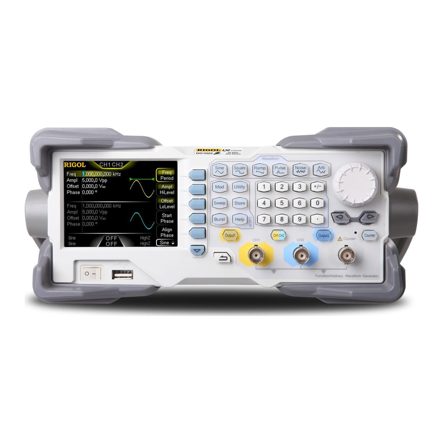
RIGOL Chapter 1 Quick Start Appearance and Dimensions Front View Unit: mm Side View Unit: mm DG1000Z User’s Guide... -
Page 23: Front Panel Overview
(*.Bmp) into the USB storage device. TMC DS: seamlessly interconnect with the RIGOL DS that meets the TMC standard. Read and store the waveform data collected by the DS and rebuilt waveform losslessly. - Page 24 RIGOL Chapter 1 Quick Start 3. Page Up/Down Open the next page of the current function menu or return to the first page. 4. Return to the Previous Menu Exit the current menu and return to the previous menu. 5. CH1 Output Connector BNC connector with 50Ω...
- Page 25 Chapter 1 Quick Start RIGOL 8. Input Connector for the Signal Measured by Counter BNC connector with 1MΩ input impedance. It is used to accept the signal measured by the counter. CAUTION To avoid damages to the instrument, the input signal voltage can not exceed ±7Vac+dc.
- Page 26 RIGOL Chapter 1 Quick Start 13. Waveforms Key Output Sine with frequency from 1μHz to 60MHz. — The backlight turns on when this function is selected. — You can set Freq/Period, Ampl/HiLevel, Offset/LoLevel and Start Phase of sine waveform. Output Square with frequency from 1μHz to 25MHz and variable duty cycle.
- Page 27 Chapter 1 Quick Start RIGOL 14. Function keys Output multiple types of modulated waveforms. — Support multiple modulation types: AM, FM, PM, ASK, FSK, PSK and PWM. — Support internal and external modulation sources. — The backlight turns on when this function is selected.
- Page 28 RIGOL Chapter 1 Quick Start 15. Menu Softkeys Correspond to the left displayed menus respectively. Press this softkey to activate the corresponding menu. 16. LCD 3.5 inches TFT (320×240) color LCD display. The current function menu, settings, system state as well as prompt messages and etc. can be clearly displayed (for the detailed information, refer to “User Interface”).
-
Page 29: Rear Panel Overview
Chapter 1 Quick Start RIGOL Rear Panel Overview The rear panel of DG1000Z is as shown in the figure below. Click the numbers in the figure to view the corresponding description. Figure 1-2 Rear Panel 1. [CH1/Sync/Ext Mod/Trig/FSK] BNC female connector with 50Ω nominal impedance. - Page 30 RIGOL Chapter 1 Quick Start selected, this connector accepts an external trigger signal whose polarity can be set by users. 5) Trig Out When Sweep or Burst of CH1 is enabled and internal or manual trigger source is selected, this connector outputs a trigger signal with specified edge type.
- Page 31 Chapter 1 Quick Start RIGOL accepts an external 10MHz clock signal. This connector is typically used to synchronize multiple instruments. For more detailed information about the signals mentioned above, please refer to the introduction in “Clock Source”. 4. LAN Used to connect the generator to your computer or the network of your computer for remote control.
-
Page 32: Power On And Inspection
RIGOL Chapter 1 Quick Start Power On and Inspection To Connect to Power Please connect the generator to AC power supply using the power cord supplied in the accessories (as shown in the figure below). The AC power supply specification of this generator is 100-240V, 45-440Hz. -
Page 33: User Interface
Chapter 1 Quick Start RIGOL User Interface DG1000Z user interface includes three types of display modes: Dual Channels Parameters (default), Dual Channels Graph and Single Channel View. In this manual, the Dual Channels Parameters display mode is mainly taken as an example to introduct the user interface. - Page 34 RIGOL Chapter 1 Quick Start 2. Current Function and Page Up/Down Indicator Display the name of the function selected currently. For example, “Sine” is displayed when the sine is selected and “Edit” is displayed when the arbitrary waveform editing function is selected. Besides, the up and down arrows at the right of the function name are used to indicate whether page up/down is permitted now.
- Page 35 Chapter 1 Quick Start RIGOL 9. Offset Display the waveform DC offset of the channel. Press Offset/LoLevel to highlight “Offset” and use the numeric keyboard or direction keys and knob to modify this parameter. 10. Phase Display the waveform start phase of the channel. Press Start Phase and use the numeric keyboard or direction keys and knob to modify this parameter.
-
Page 36: Dual Channels Graph Mode
RIGOL Chapter 1 Quick Start Dual Channels Graph Mode Press Utility System Display DispMod to select “Dual Graph”, as shown in the figure below. Figure 1-5 User Interface (Dual Channels Graph Mode) Single Channel View Mode Press Utility System Display DispMode to select “Single View”, as shown in the figure below. -
Page 37: To Use The Built-In Help System
Chapter 1 Quick Start RIGOL To Use the Built-in Help System DG1000Z built-in help system provides help information for each key and menu softkey at the front panel. When operating the instrument, users can view the help information of any key at any time. -
Page 39: Chapter 2 Front Panel Operations
Chapter 2 Front Panel Operations RIGOL Chapter 2 Front Panel Operations This chapter introduces the main functions and operation methods of DG1000Z. Subjects in this chapter: To Output Basic Waveform To Output Arbitrary Waveform To Output Harmonic ... -
Page 40: To Output Basic Waveform
RIGOL Chapter 2 Front Panel Operations To Output Basic Waveform DG1000Z series can output basic waveforms (Sine, Square, Ramp, Pulse and Noise) from one of the channels separately or from the two channels at the same time. At start-up, the dual channels are configured to output a sine waveform with 1kHz frequency and 5Vpp amplitude by default. -
Page 41: To Select Basic Waveform
Chapter 2 Front Panel Operations RIGOL To Select Basic Waveform DG1000Z can output 5 types of basic waveforms including Sine, Square, Ramp, Pulse and Noise. The five function keys at the front panel are used to select the corresponding waveform. Press the corresponding key to select the desired waveform. -
Page 42: To Set Frequency/Period
RIGOL Chapter 2 Front Panel Operations To Set Frequency/Period Frequency is one of the most important parameters of basic waveforms. For different instrument models and waveforms, the setting ranges of frequency are different. For detailed information, please refer to “Frequency Characteristics” in “Specifications”. -
Page 43: To Set Amplitude/High Level
Chapter 2 Front Panel Operations RIGOL To Set Amplitude/High Level The amplitude setting range is limited by the “Impedance” and “Freq/Period” settings. Please refer to “Output Characteristics” in “Specifications”. The default value is 5Vpp. The amplitude displayed on the screen is the default value or the amplitude previously set. - Page 44 RIGOL Chapter 2 Front Panel Operations Vamp Vrms=0.707Vamp Vpp=2Vamp According to the figure above, the conversion relation between Vpp and Vrms fulfills the following equation: Vpp = Vrms For example, if the current amplitude is 5Vpp, press · in the numeric keyboard and select “Vrms”...
-
Page 45: To Set Offset/Low Level
Chapter 2 Front Panel Operations RIGOL To Set Offset/Low Level The DC offset setting range is limited by the “Impedance” and “Ampl/HiLevel” settings. Please refer to the “Output Characteristics” in “Specifications”. The default value is 0V The DC offset voltage displayed on the screen is the default value or the offset previously set. -
Page 46: To Set Start Phase
RIGOL Chapter 2 Front Panel Operations To Set Start Phase The setting range of start phase is from 0° to 360° and the default is 0°. The start phase displayed on the screen is the default value or the phase previously set. -
Page 47: Align Phase
Chapter 2 Front Panel Operations RIGOL Align Phase DG1000Z series dual-channel generators enable to align the phases of the two channels. Pressing down this softkey will re-configure the two channels and enable the generator to output with specified frequency and start phase. -
Page 48: To Set Duty Cycle (Square)
RIGOL Chapter 2 Front Panel Operations To Set Duty Cycle (Square) Duty cycle is defined as the percentage that the high level takes up in the whole period (as shown in the figure below). This parameter is only available when square is selected. -
Page 49: To Set Symmetry (Ramp)
Chapter 2 Front Panel Operations RIGOL To Set Symmetry (Ramp) Symmetry is defined as the percentage that the rising period takes up in the whole period (as shown in the figure below). This parameter is only available when ramp is selected. -
Page 50: To Set Pulse Width/Duty Cycle (Pulse)
RIGOL Chapter 2 Front Panel Operations To Set Pulse Width/Duty Cycle (Pulse) Pulse width is defined as the time from the 50% threshold of a rising edge amplitude to the 50% threshold of the next falling edge amplitude (as shown in the figure below). -
Page 51: To Set Leading/Trailing Edge Time (Pulse)
Chapter 2 Front Panel Operations RIGOL Users can also use the direction keys and knob to set the parameter value: use the direction keys to move the cursor to select the digit to be edited and then rotate the knob to change the number. -
Page 52: To Enable Output
RIGOL Chapter 2 Front Panel Operations To Enable Output After configuring the parameters of the waveform selected, waveform output could be enabled. Before enabling waveform output, you can also configure parameters (such as Impedance and Polarity) related to the channel output through Channel Set menu in Utility. -
Page 53: Example: To Output Sine Waveform
Chapter 2 Front Panel Operations RIGOL Example: To Output Sine Waveform This section mainly introduces how to output a sine waveform (Frequency: 20kHz, Amplitude: 2.5Vpp, DC Offset: 500 mV , Start Phase: 90°) from the [CH1] connector. 1. To select output channel Press CH1|CH2 to select CH1. - Page 54 RIGOL Chapter 2 Front Panel Operations Figure 2-3 Sine Waveform 2-16 DG1000Z User’s Guide...
-
Page 55: To Output Arbitrary Waveform
DG1000Z provides 2Mpts (2M data points, applied to DG1022Z) standard memory depth, 8Mpts (8M data points, applied to DG1032Z and DG1062Z) standard memory depth and a 16Mpts memory depth option for user-defined arbitrary waveforms. When editing the waveform on the instrument, 8pts to 8kpts data points are available in period editing mode and 8pts to 16kpts data points are available in sample rate editing mode. -
Page 56: Output Mode And Sample Rate
RIGOL Chapter 2 Front Panel Operations Please refer to “To Output Basic Waveform” to configure the parameters and output of the channels. This chapter will focus on “Sample Rate”, “Output Mode”, “Select Waveform” and “Edit Waveform”. Output Mode and Sample Rate DG1000Z supports Frequency and Sample Rate output modes. -
Page 57: To Select Arbitrary Waveform
Chapter 2 Front Panel Operations RIGOL To Select Arbitrary Waveform DG1000Z allows users to select DC, 160 built-in waveforms, and arbitrary waveforms stored in internal or external memory of the instrument and volatile memory. KEY POINTS: After the desired waveform is selected, you can perform the operations below. - Page 58 RIGOL Chapter 2 Front Panel Operations Built-In Waveform DG1000Z has 160 built-in arbitrary waveforms as shown in Table 2-2. Press Arb Select Wform BuiltIn to enter the built-in waveform selection interface as shown in the figure below. Press Engine, Medical, AutoElec or Maths to select the corresponding item (each item has one or more sub-items).
- Page 59 Chapter 2 Front Panel Operations RIGOL StairUp Stair-up waveform Trapezia Trapezia waveform AmpALT Gain oscillation curve AttALT Attenuation oscillation curve RoundHalf RoundHalf Wave RounsPM RoundsPM Waveform BlaseiWave Time-velocity curve of explosive vibration Engine DampedOsc Time-displacement curve of damped oscillation SwingOsc...
- Page 60 RIGOL Chapter 2 Front Panel Operations ECG1 Electrocardiogram 1 ECG2 Electrocardiogram 2 ECG3 Electrocardiogram 3 ECG4 Electrocardiogram 4 ECG5 Electrocardiogram 5 ECG6 Electrocardiogram 6 ECG7 Electrocardiogram 7 ECG8 Electrocardiogram 8 ECG9 Electrocardiogram 9 ECG10 Electrocardiogram 10 ECG11 Electrocardiogram 11 ECG12...
- Page 61 Chapter 2 Front Panel Operations RIGOL Error function Erfc Complementary error function ErfcInv Inverted complementary error function ErfInv Inverted error function ExpFall Exponential fall function ExpRise Exponential rise function HaverSine HaverSine function Laguerre 4-times Laguerre polynomial Legend 5-times Legend polynomial...
- Page 62 RIGOL Chapter 2 Front Panel Operations ACotHPro Protuberant arc hyperbolic cotangent ACscCon Concave arc cosecant ACscPro Protuberant arc cosecant ACscHCon Concave arc hyperbolic cosecant ACscHPro Protuberant arc hyperbolic cosecant ASecCon Concave arc secant ASecPro Protuberant arc secant ASecH Arc hyperbolic secant...
- Page 63 Chapter 2 Front Panel Operations RIGOL Volatile Waveform Press Arb Select Wform Volatile Wform to select arbitrary waveform currently stored in the volatile memory. If there is no waveform data in volatile memory currently, this menu would be unavailable. At this time, you can fill up the volatile memory through the methods below.
-
Page 64: To Edit Arbitrary Waveform
RIGOL Chapter 2 Front Panel Operations To Edit Arbitrary Waveform DG1000Z allows users to edit the waveform in the volatile memory of the channel currently selected. If there is no waveform data in the volatile memory currently, the system will automatically creat 8 (sample rate edit mode) or 8192 (period edit mode) data points whose voltage are low level. - Page 65 Chapter 2 Front Panel Operations RIGOL total number of points of the waveform currently edited. The range is from 8 to 16384 (namely 16k) and the default is 8. Users can select the numbers of Sa points and set their voltages respectively.
- Page 66 RIGOL Chapter 2 Front Panel Operations Cycles Set the cycles of the inserted waveform. The range is from 1 to 16 and the default is 1. The each cycle’s points of the inserted waveform is fixed at 1024. Select Waveform ...
- Page 67 Chapter 2 Front Panel Operations RIGOL currently edited and set the voltage of the current point to low level. Press Move Pos and input the number (the range is from 1 to Sa) of the point to move to before pressing OK. You can also rotate the knob to select the number of the point to move to after pressing Move Pos.
-
Page 68: To Output Harmonic
RIGOL Chapter 2 Front Panel Operations To Output Harmonic DG1000Z can be used as a harmonic generator to output harmonic with specified order, amplitude and phase. It is usually used in the test of harmonic detector device or harmonic filter device. This section introduces how to configure the generator to output harmonic. -
Page 69: To Set Fundamental Waveform Parameters
Chapter 2 Front Panel Operations RIGOL To Set Fundamental Waveform Parameters DG1000Z allows users to set various fundamental waveform parameters such as frequency, period, amplitude, DC offset voltage, high level, low level and start phase. It also supports align phase operation. Please refer to introductions in “To Output Basic Waveform”... -
Page 70: To Set Harmonic Amplitude
RIGOL Chapter 2 Front Panel Operations 8 bits binary data is used to represent the output status of the 8 orders of harmonics respectively, wherein, 1 represents enabling the output of the corresponding harmonic and 0 represents disabling the output of the corresponding harmonic. -
Page 71: Example: To Output Harmonic
Chapter 2 Front Panel Operations RIGOL Example: To Output Harmonic This section introduces how to output 2th order of harmonic (harmonic amplitude: 2Vpp, harmonic phase: 30°) and 4th orders of harmonic (harmonic amplitude: 1Vpp, harmonic phase: 50°) from the [CH1] connector. The fundamental waveform is the default sine of the instrument and the harmonic order is 5. - Page 72 RIGOL Chapter 2 Front Panel Operations 8. To Enable the Output: Press Output1 and the backlight turns on. The fundamental waveform, 2th and 4th order of harmonics will be outputted from the [CH1] connector according to the current configuration. 9. To Observe the Output Waveform: Connet the CH1 of the DG1000Z to an oscilloscope using BNC connect cable.
-
Page 73: Modulation
Chapter 2 Front Panel Operations RIGOL Modulation DG1000Z can output modulated waveform from a single channel or from two channels at the same time. Modulation is the process of modifying certain parameters (such as amplitude, frequency, phase and etc.) of the carrier waveform signal according to the change of the modulating signal. - Page 74 RIGOL Chapter 2 Front Panel Operations When the carrier waveform currently selected is arbitrary waveform, please refer to the introduction in “To Output Arbitrary Waveform” to set the parameters of the carrier waveform currently selected. To Select Modulation Source DG1000Z can accept modulating waveform from internal or external modulation source.
- Page 75 Chapter 2 Front Panel Operations RIGOL KEY POINTS: How to realize the intermodulation between dual channels? The following example takes the output signal of CH2 as the modulating waveform. Connect the CH2 output terminal to [CH1/Sync/Ext Mod/Trig/FSK] connector at the rear panel using the dual BNC connect cable.
- Page 76 RIGOL Chapter 2 Front Panel Operations Carrier Waveform Suppression DG1000Z supports the normal amplitude modulation and double sideband suppressed carrier (DSB-SC) amplitude modulation. In the normal amplitude modulation, the modulated waveform contains carrier waveform components. Because carrier waveform components carry no information, the modulation is less efficient.
-
Page 77: Frequency Modulation (Fm)
Chapter 2 Front Panel Operations RIGOL Frequency Modulation (FM) For frequency modulation (FM), the frequency of the carrier waveform varies with the instantaneous voltage of the modulating waveform. To Select FM Modulation Press Mod Type FM to enable FM function. When Mod is enabled, Sweep or Burst will be disabled automatically (if enabled currently). - Page 78 RIGOL Chapter 2 Front Panel Operations To Select Modulation Source DG1000Z can accept modulating waveform from internal or external modulation source. Press Mod Source to select “Int” or “Ext” modulation source. 1. Internal Source When internal modulation source is selected, press Shape to select Sine, Square, Triangle, UpRamp, DnRamp, Noise or Arb as modulating waveform.
- Page 79 Chapter 2 Front Panel Operations RIGOL To Set Modulating Waveform Frequency When internal modulation source is selected, press FM Freq to set the modulating waveform frequency. Input the desired frequency value using the numeric keyboard or direction keys and knob.
-
Page 80: Phase Modulation (Pm)
RIGOL Chapter 2 Front Panel Operations Phase Modulation (PM) For phase modulation (PM), the phase of the carrier waveform varies with the instantaneous voltage of the modulating waveform. To Select PM Modulation Press Mod Type PM to enable PM function. When Mod is enabled, Sweep or Burst will be disabled automatically (if enabled currently). - Page 81 Chapter 2 Front Panel Operations RIGOL To Select Modulation Source DG1000Z can accept modulating waveform from internal or external modulation source. Press Mod Source to select “Int” or “Ext” modulation source. 1. Internal Source When internal modulation source is selected, press Shape to select Sine, Square, Triangle, UpRamp, DnRamp, Noise or Arb as modulating waveform.
- Page 82 RIGOL Chapter 2 Front Panel Operations To Set Modulating Waveform Frequency When internal modulation source is selected, press PM Freq to set the modulating waveform frequency. Input the desired frequency value using the numeric keyboard or direction keys and knob。...
-
Page 83: Amplitude Shift Keying (Ask)
Chapter 2 Front Panel Operations RIGOL Amplitude Shift Keying (ASK) When using ASK (Amplitude Shift Keying), you can configure the generator to “shift” its output amplitude between two preset amplitude values (“carrier amplitude” and “modulating amplitude”). To Select ASK Modulation Press Mod ... - Page 84 RIGOL Chapter 2 Front Panel Operations To Select Modulation Source Press Mod Source to select “Int” or “Ext” modulation source. 1. Internal Source When internal source is selected, the modulating waveform is set as a Square with 50% duty cycle, and the frequency at which the output amplitude “shifts”...
- Page 85 Chapter 2 Front Panel Operations RIGOL To Set Modulating Amplitude Press ASK Ampl to set the modulating amplitude。 Use the numeric keyboard or direction keys and knob to input the desired amplitude value. The range of amplitude (HighZ) is from 0 to 10Vpp and the default is 2Vpp.
-
Page 86: Frequency Shift Keying (Fsk)
RIGOL Chapter 2 Front Panel Operations Frequency Shift Keying (FSK) When FSK (Frequency Shift Keying) modulation is selected, you can configure the generator to “shift” its output frequency between two preset frequencies (“carrier frequency” and “hop frequency”). To Select FSK Modulation Press Mod ... - Page 87 Chapter 2 Front Panel Operations RIGOL To Select Modulation Source Press Mod Source to select “Int” or “Ext” modulation source. 1. Internal Source When internal source is selected, the modulating waveform is set as a Square with 50% duty cycle, and the frequency at which the output frequency “shifts”...
- Page 88 RIGOL Chapter 2 Front Panel Operations To Set Hop Frequency Hop frequency is the modulating frequency. The range of hop frequency depends on the carrier waveform currently selected. Press HopFreq to highlight it and input the desired frequency value using the numeric keyboard or direction keys and knob.
-
Page 89: Phase Shift Keying (Psk)
Chapter 2 Front Panel Operations RIGOL Phase Shift Keying (PSK) When PSK (Phase Shift Keying) modulation is selected, you can configure the generator to “shift” its output phase between two preset phase values (“carrier phase” and “modulating phase”). To Select PSK Modulation Press Mod ... - Page 90 RIGOL Chapter 2 Front Panel Operations To Select Modulation Source Press Mod Source to select “Int” or “Ext” modulation source. 1. Internal Source When internal source is selected, the modulating waveform is set as a Square with 50% duty cycle, and the frequency at which the output phase “shifts”...
- Page 91 Chapter 2 Front Panel Operations RIGOL To Set Modulating Phase Press Phase to set the modulating phase. Use the numeric keyboard or direction keys and knob to input the desired phase value. The phase range is from 0° to 360° and the default is 180°.
-
Page 92: Pulse Width Modulation (Pwm)
RIGOL Chapter 2 Front Panel Operations Pulse Width Modulation (PWM) For PWM (Pulse Width Modulation), the pulse width of the carrier waveform varies with the instantaneous voltage of the modulating waveform. To Select PWM Modulation PWM can only be used to modulate pulse. To select PWM modulation, press Pulse at the front panel first and then press Mod to enable PWM function. - Page 93 Chapter 2 Front Panel Operations RIGOL To Select Modulation Source Press Mod Source to select “Int” or “Ext” modulation source. 1. Internal Source When internal modulation source is selected, press Shape to select Sine, Square, Triangle, UpRamp, DnRamp, Noise or Arb as modulating waveform. The default is Sine.
- Page 94 RIGOL Chapter 2 Front Panel Operations To Set Pulse Width/Duty Cycle Deviation Press Width DeV (or Duty Dev) and input the desired value using the numeric keyboard or direction keys and knob. Width deviation represents the variation (the available units are ns, μs, ms, s ...
-
Page 95: Sweep
Chapter 2 Front Panel Operations RIGOL Sweep DG1000Z can output sweep from a single channel or from dual channels at the same time. In sweep mode, the generator outputs signal variably from the start frequency to stop frequency within the specified sweep time. DG1000Z supports linear, log and... -
Page 96: Center Frequency And Frequency Span
RIGOL Chapter 2 Front Panel Operations Center Frequency and Frequency Span You can also set the frequency boundaries of frequency sweep through center frequency and frequency span. Center Frequency = (|Start Frequency + Stop Frequency|) / 2 Frequency Span = Stop Frequency – Start Frequency ... -
Page 97: Sweep Type
Chapter 2 Front Panel Operations RIGOL Sweep Type DG1000Z provides Linear, Log and Step sweep types and the default is Linear sweep. Linear Sweep In linear sweep type, the output frequency of the instrument varies linearly in the way of “several Hertz per second”. The variation is controlled by “Start Frequency”, “Stop Frequency”... -
Page 98: Sweep Time
RIGOL Chapter 2 Front Panel Operations Figure 2-8 Log Sweep Step Sweep In Step Sweep type, the output frequency of the instrument “steps” from “Start Frequency” to “Stop Frequency”. The duration of the output signal on each frequency point is determined by “Sweep Time” and “Step Number”. -
Page 99: Mark Frequency
Chapter 2 Front Panel Operations RIGOL The generator will renewedly sweep from the specified “Start Frequency” once the return time is modified. Mark Frequency The sync signal output from the [CH1/Sync/Ext Mod/Trig/FSK] connector (corresponds to the channel at the front panel) at the rear panel always changes from low level to high level at the start of each sweep. -
Page 100: Stop Hold
RIGOL Chapter 2 Front Panel Operations Stop Hold Stop Hold is the duration that the output signal still outputs with the “Stop Frequency” after the generator has swept from the “Start Frequency” to the “Stop Frequency”. When Sweep is enabled, press Stop Hold and use the numeric keyboard or direction keys and knob to change the stop hold. - Page 101 Chapter 2 Front Panel Operations RIGOL [CH2/Sync/Ext Mod/Trig/FSK] [CH1/Sync/Ext Mod/Trig/FSK] 3. Manual Trigger A sweep will be generated from the corresponding channel once you press Trigger when manual trigger is selected. Note: the menu key Trigger is valid when the “Manual Trigger” is selected and the output of the corresponding channel is enabled.
- Page 102 RIGOL Chapter 2 Front Panel Operations When “Ext” trigger is selected, press Sweep Trigger TrigOut to select “Leading” or “Trailing”. The [CH1/Sync/Ext Mod/Trig/FSK] connector at the rear panel is used as the input terminal of external trigger signal. The...
-
Page 103: Burst
Chapter 2 Front Panel Operations RIGOL Burst DG1000Z can output waveform with specified number of cycles (called Burst) from a single channel or from dual channels at the same time. DG1000Z supports control of burst output by internal, manual or external trigger source; supports three kinds of burst types including N cycle, infinite and gated. - Page 104 RIGOL Chapter 2 Front Panel Operations Figure 2-10 N Cycle Burst For N cycle burst, “Int”, “Ext” or “Manual” trigger source could be used. Besides, you can also set the “Burst Period” (internal trigger), “Delay”, “SlopeIn” (external trigger) and “TrigOut” (internal and manual trigger).
-
Page 105: Burst Period
Chapter 2 Front Panel Operations RIGOL Figure 2-12 Gated Burst When the gated signal is “True”, the generator outputs a continuous waveform. When the gated signal is “False”, the generator first completes the output of the current period and then stops. For Noise waveform, the output will stop immediately once the gated signal becomes “False”. -
Page 106: Burst Delay
RIGOL Chapter 2 Front Panel Operations Burst Delay Burst delay is only available for N cycle and infinite burst mode. It is defined as the time from when the generator receives the trigger signal to starts to output the N Cycle (or Infinite) burst. -
Page 107: Idle Level
Chapter 2 Front Panel Operations RIGOL 3. Manual Trigger When manual trigger is selected, the generator can output infinite or gated burst. A burst will be generated from the corresponding channel (if currently turned on) once you press Trigger. If the corresponding channel is not turned on, Trigger will be grayed out and disabled. -
Page 108: Counter
RIGOL Chapter 2 Front Panel Operations Counter DG1000Z provides a counter which can measure various parameters (such as frequency, period, duty cycle, positive pulse width and negative pulse width) of external input signal and support statistic of measurement results. When the statistic... -
Page 109: To Set The Counter
Chapter 2 Front Panel Operations RIGOL To Set the Counter You need to configure appropriate parameters for the counter. 1. Gate Time Press Gate Time to set the gate time of the measurement system and the default is “1.310ms”. 1.310ms 10ms 10.48ms... - Page 110 RIGOL Chapter 2 Front Panel Operations Figure 2-15 Statistic Results Interface (In “Digital” Display Mode) Note: when the statistic function is disabled, Display is grayed out and disabled. Figure 2-16 Statistic Results Interface (In “Curve” Display Mode) 2) To clear the statistic results Press Clear to clear the current statistic result。...
- Page 111 Chapter 2 Front Panel Operations RIGOL 4. Trigger Sensitivity Set the trigger sensitivity of the measurement system. The default is 25% and the range available is from 0% to 100%. Press TrigSens and use the numeric keyboard to input the desired value and select the unit “%” from the pop-up menu.
-
Page 112: Store And Recall
DG1000Z can store the current instrument state and user-defined arbitrary waveform data in internal or external memory and recall them when needed. DG1000Z also could interconnect with RIGOL oscilloscope which supports USB-TMC seamlessly and rebuilt and output the waveform data collected by the oscilloscope losslessly. -
Page 113: File Type
Chapter 2 Front Panel Operations RIGOL Note: DG1000Z can only identify files of which filenames consist of Chinese characters, English letters, number and underscore. If other characters are used to name the file or folder, the name might be displayed in the store and recall interface abnormally. - Page 114 RIGOL Chapter 2 Front Panel Operations 3. Txt File Read the Txt files stored in external memory. The data of each line (can not be longer than 64 characters) is considered as an arbitrary waveform point and the data of all lines in the file are normalized to form an arbitrary waveform. The arbitrary waveform is stored in volatile memory.
-
Page 115: Browser Type
Chapter 2 Front Panel Operations RIGOL Browser Type Press Store Browser to switch between “Dir” and “File”. Use the knob to select the desired directory or file. Dir: when this type is selected, use the knob to switch between C Disk and D ... - Page 116 RIGOL Chapter 2 Front Panel Operations 3. To Input Filename Press IME to select “Chinese” or “English”. The length of the file or folder name is limited within 9 characters. English Input (include number input): Press +/- on the numeric keyboard at the front panel to switch between uppercase and lowercase.
- Page 117 Chapter 2 Front Panel Operations RIGOL character in the “Pinyin Input Area” and then delete the Chinese character at the cursor currently in the “Filename Input Area”. 4. To Save File After finishing inputting filename in the filename input interface, press Save, the generator will save the file under the currently selected directory with the specified filename and file type.
- Page 118 RIGOL Chapter 2 Front Panel Operations 4. To Paste File Press Paste, the generator will paste the copied file in the directory which the current cursor is in and display corresponding prompt message after finishing the paste operation. Delete 1. To Select File or Folder to be Deleted Set Browser to “Dir”...
-
Page 119: Seamless Interconnection With Oscilloscope
Chapter 2 Front Panel Operations RIGOL Seamless Interconnection with Oscilloscope DG1000Z could interconnect with RIGOL oscilloscope which supports USB-TMC seamlessly and rebuilt and output the waveform data collected by the oscilloscope losslessly. The connection method between the instruments is as shown in the figure below. - Page 120 RIGOL Chapter 2 Front Panel Operations of DS1 will be displayed in the “File/Folder Display Area”. Set the Browser menu of DG1000Z as “File”, and move the cursor onto the channel to be read, and then press Read. At this point, DS1 will enter the “Stop” mode automatically, and DG1000Z will read the arbitrary waveform data (namely the waveform data collected by DS1) automatically.
-
Page 121: Utility And System Settings
Chapter 2 Front Panel Operations RIGOL Utility and System Settings Press Utility at the front panel to open the operation interface as shown in the figure below. This interface displays the output configuration, coupling configuration and system parameters of the currently selected channel. -
Page 122: Channel Set
RIGOL Chapter 2 Front Panel Operations Channel Set For DG1000Z, the function and setting method of CH1 are the same to those of CH2. This section takes CH1 for example to illustrate how to set the channel. To set the output parameters of CH2, please press CH1|CH2 to select CH2 and refer to this section to set the parameters. - Page 123 Chapter 2 Front Panel Operations RIGOL KEY POINTS: Sync Signals of Various Waveforms: 1. Basic Waveform The frequency of the basic waveform is less than or equal to 100kHz or the sync delay is not 0: The sync signal is a Square with 50% duty cycle and the same frequency as that of the basic waveform.
- Page 124 RIGOL Chapter 2 Front Panel Operations 4. Modulated Waveform (the sync delay is invalid) When internal modulation source is selected: the sync signal is a square with 50% duty cycle. For AM, FM, PM and PWM, the frequency of the sync signal is the ...
- Page 125 Chapter 2 Front Panel Operations RIGOL 6. Burst Waveform(the sync delay is invalid) When internal or munual trigger source is selected: Infinite burst: the sync signal is the same as that of the basic waveform. N cycle burst: the sync signal is TTL high level at the start of the ...
- Page 126 RIGOL Chapter 2 Front Panel Operations 2. Output Impedance The output impedance setting influences output amplitude and DC offset. The instrument has a 50Ω fixed serial output impedance for the [CH1] connector at the front panel. If the actual load is different from the specified value, the voltage level displayed would not match the voltage level of the device under test.
- Page 127 Chapter 2 Front Panel Operations RIGOL Waveform Summing 1. To Enable Waveform Summing Function Press Utility Channel Set Sum Wforms Switch, select “On” to enable the waveform summing function and sum a specified waveform on the current waveform or select “Off” to disable the waveform summing function.
-
Page 128: Coupling Set
RIGOL Chapter 2 Front Panel Operations Coupling Set DG1000Z supports frequency, amplitude and phase couplings. Users can set the frequency deviation (frequency ratio), amplitude deviation (amplitude ratio) or phase deviation (phase ratio) of the two channels. When coupling is enabled, CH1 and CH2 are mutual base source. - Page 129 Chapter 2 Front Panel Operations RIGOL 2. To Enable Coupling Function Press Ampl Cpl to turn amplitude coupling “On” or “Off”. The default is “Off”. Phase Coupling 1. Phase Coupling Mode Press PCpl Mode to select “PhaseDev” or “Ratio” and then input the desired value using the numeric keyboard.
- Page 130 RIGOL Chapter 2 Front Panel Operations Figure 2-21 Channel Coupling KEY POINTS: Channel coupling is only available when both the waveforms of the two channels are basic waveforms including Sine, Square, Ramp and Arbitrary waveform (except DC). If the sum (or product) of the frequency, amplitude or phase of CH1 and the ...
-
Page 131: Channel Copy
Chapter 2 Front Panel Operations RIGOL Track Press Track to select the track mode as “On”, “Invert” or “Off”. On: enable the track function. The instrument copies the various parameters and states (except the channel output state) of CH1 to CH2 automatically. When... -
Page 132: Restore Default
RIGOL Chapter 2 Front Panel Operations Restore Default Restore the instrument to its default state. Press Utility Set To Default OK, the backlight of Utility turns off and switch the instrument to Sine display mode. The default values are shown in the table below. - Page 133 Chapter 2 Front Panel Operations RIGOL Harmonic State User-defined X0000000 Arb Waveform Sample Rate 20MSa/s DC Offset Arb Waveform Mode Frequency Built-in Arbitrary Waveform Sinc Insret Waveform Insert position Insert Way Insert Cycles Points High Level 2.5V Low Level -2.5V...
- Page 134 RIGOL Chapter 2 Front Panel Operations ASK Rate 100Hz Modulation Amplitude 2Vpp ASK Polarity FSK Modulation Modulation Source FSK Rate 100Hz Hop Frequency 10kHz FSK Polarity PSK Modulation Modulation Source PSK Rate 100Hz PSK Phase 180° PSK Polarity PWM Modulation...
- Page 135 Chapter 2 Front Panel Operations RIGOL Trigger Input Leading Delay Interface Focus Items Frequency/Period Freq Amplitude/High Level Ampl Offset/Low Level Offset Pulse Width/Duty Cycle Duty Start/Center Start Stop/Span Stop Frequency Coupling Deviation/Ratio Ratio Amplitude Coupling Deviation/Ratio Ratio Phase Coupling Deviation/Ratio...
- Page 136 RIGOL Chapter 2 Front Panel Operations UI Customization Set Coordinate* (0,0) System Set Power On Setting Default Clock Source Decimal Point Thousand Separator Comma Beeper Screen Saver Brightness* Contrast* Display Mode* Dual Channels Parameters Language* Factory Delivery Setting I/O Configuration...
-
Page 137: To Set System Languege
Chapter 2 Front Panel Operations RIGOL To Set System Languege At present, DG1000Z supports menus in various languages as well as provides Chinese/English help information, prompt messages, interface display and Chinese/English input method. Press Utility Language to select the desired language. This setting is stored in non-volatile memory and will not be influenced by the Set To Default operation. -
Page 138: System Set
RIGOL Chapter 2 Front Panel Operations System Set Power On Set Set the configuration to be used when the instrument is powered on the next time to “Default” or “Last”. The default setting is “Default”. Last: includes all system parameters and states, except channel output state ... - Page 139 Chapter 2 Front Panel Operations RIGOL generators (“External” clock) respectively, and finally set the output frequencies of all the generators as a same value to realize synchronization among multiple instruments. Number Format You can set the display format of the decimal point and thousands separator in number parameters.
-
Page 140: Display Mode
RIGOL Chapter 2 Front Panel Operations Display Set Press Utility System Display to enter the display setting interface. You can set the brightness, contrast and display mode. Besides, you can also customize the start-up interface. 1. Brightness Press Brightness and use the numeric keyboard or direction keys and knob to change the brightness. -
Page 141: I/O Configuration
Chapter 2 Front Panel Operations RIGOL press Preview to preview the effect of the user-defined start-up interface. Press any key to quit the preview. Save: save the defined start-up interface and this interface will be displayed at the next start-up. - Page 142 RIGOL Chapter 2 Front Panel Operations Network Status Different prompt messages will be provided by the generator based on the current network status. Connected: indicates LAN connection is successful. Disconnect: indicates no LAN connection or LAN connection is unsuccessful.
- Page 143 Chapter 2 Front Panel Operations RIGOL Press AutoIP to select “On” or “Off” to turn AutoIP mode on or off. The default is “On”. When DHCP and AutoIP modes are turned on at the same time, the instrument will first use DHCP mode. Therefore, to enable this mode, set DHCP as “Off”.
- Page 144 RIGOL Chapter 2 Front Panel Operations recommended that users acquire an available default gateway from their network administrator. Press Default Gateway and use the direction keys and numeric keyboard or knob to enter your desired gateway address. The setting is stored in non-volatile memory and will be automatically loaded when the generator is powered on the next time if DHCP and AutoIP are set as “Off”.
-
Page 145: Print Set
Ok to enter the manual calibration interface. At this time, you can calibrate the instrument manually. A default password is set when factory delivery and please contact RIGOL if you want to acquire this password. If you have already known the password, you could modify the password (press Password Modify and modify the password according to the interface prompts). -
Page 146: To Use External Power Amplifier (Option)
Power Amplifier (PA) and DG1000Z will amplify the signal before output. To use external power amplifier, please install the PA1011 option. PA1011 is one of the options provided for RIGOL DG Series Function/Arbitrary Waveform Generators, with up to 1 MHz full power bandwidth and higher than 80 V/µs slew rate. - Page 147 Chapter 2 Front Panel Operations RIGOL Front Panel: Status Indicator Signal Output Signal Input Status Indicator Power: red light on, indicating successful power connection. Output: green light on, indicating that PA output is turned on. Link: yellow light on, indicating successful USB connection.
- Page 148 RIGOL Chapter 2 Front Panel Operations Rear Panel: USB Device Power In Fan Aperture CAUTION Do not use any other adapters to supply power for PA1011, or else it may cause degradation or perpetual damage. CAUTION Please make sure the vents at both sides and the fan aperture at the rear panel are visible in operation for normal working.
- Page 149 Chapter 2 Front Panel Operations RIGOL Connect DG1000Z with PA1011: Output BNC Cable Input PA1011 DG1000Z USB Host USB Cable USB Device Output When the connection between DG1000Z and PA1011 as shown in the figure above succeeds, press Utility PA Set at the front panel of DG1000Z to enter the PA parameters setting interface.
-
Page 150: To Install The Option
Arb16M-DG1000Z), you can obtain the corresponding key. You can install the option following the steps below. Acquire the license of the option Log in the RIGOL official website. Click SERVICE Software License Register to enter the license generation interface. - Page 151 Chapter 2 Front Panel Operations RIGOL The option installation procedures: Edit the option installation file according to the above requirements and store it into a USB storage device. Turn on the instrument and insert the USB storage device. Press Store ...
-
Page 152: To Lock The Keyboard
RIGOL Chapter 2 Front Panel Operations To Lock the Keyboard You can lock any key or all the keys at the front panel using the keyboard lock command by the following two ways. 1. Keyboard Lock Command Introduction :SYSTem:KLOCk <key>,{ON|OFF|0|1} /*Lock or unlock the specified key*/ :SYSTem:KLOCk? <key>... - Page 153 Chapter 2 Front Panel Operations RIGOL Filename Suffix Command Blank Line The filename suffix must be “.scpi”. The file content requirements: The first line: the command used to lock the specified key; The second line: a blank line (cannot be omitted).
-
Page 155: Chapter 3 Remote Control
GPIB interface converter provided by RIGOL) instrument buses. This chapter will give a detailed introduction of how to use Ultra Sigma to control the generator (take DG1062Z as an example) remotely through various interfaces. To acquire the Ultra Sigma software, please contact RIGOL salesmen or technical support. -
Page 156: Remote Control Via Usb
Chapter 3 Remote Control Remote Control via USB 1. Connect the device Connect the USB DEVICE interface at the rear panel of DG1062Z with your PC using a USB cable. 2. Install the USB driver This generator is a USB-TMC device. Assuming that your PC has already been... - Page 157 Chapter 3 Remote Control RIGOL DG1000Z User’s Guide...
- Page 158 4. View the device resource The resources found will appear under the “RIGOL Online Resource” directory and the model number and USB interface information of the instrument will also be displayed as shown in the figure below.
-
Page 159: Remote Control Via Lan
Chapter 3 Remote Control RIGOL Remote Control via LAN 1. Connect the device Connect the generator to your PC or the LAN of your PC using a network cable. 2. Configure network parameters DHCP mode: If the network supports DHCP, the DHCP server in the network assigns network parameters (IP Address, Subnet Mask, Gateway and DNS) for the generator automatically. - Page 160 RIGOL Chapter 3 Remote Control 3. Search device resource Start up the Ultra Sigma and click . The window as shown in figure (a) is displayed. Click and the software searches for the instrument resources currently connected to the LAN and the resources found are displayed at the right of the window as shown in figure (b).
- Page 161 Chapter 3 Remote Control RIGOL 4. View device resource The resources found will appear under the “RIGOL Online Resource” directory as shown in the figure below. 5. Communication test Right click the resource name “DG1062Z (TCPIP::172.16.3.82::INSTR)” to select “SCPI Panel Control” to turn on the remote command control panel through which you can send commands and read data.
-
Page 162: Remote Control Via Gpib (Option)
RIGOL Chapter 3 Remote Control Remote Control via GPIB (Option) 1. Connect the device Connect the generator to your computer using a USB to GPIB interface converter (Option). Note: please make sure that a GPIB card has been installed to your PC. Connet... - Page 163 5. View device resource Click to return back to the main interface of Ultra Sigma. The resources found will appear under the “RIGOL Online Resource” directory as shown in the figure below. 6. Communication Test Right-click the resource name “DG1062Z (GPIB0::16::INSTR)” to select “SCPI Panel Control”...
-
Page 165: Chapter 4 Troubleshooting
This chapter lists the commonly encountered failures of DG1000Z and their solutions. When you encounter those problems, please solve them following the corresponding steps. If the problem remains still, please contact RIGOL and provide the device information of your instrument (Utility System Info). - Page 166 RIGOL Chapter 4 Troubleshooting Restarting the instrument and insert the USB storage device again to check whether it can work normally. If the USB storage device still can not be used normally, please contact RIGOL. 6. How to set the amplitude of the waveform in dBm? Press CH1|CH2 to select the desired channel.
-
Page 167: Chapter 5 Specifications
The generator has been working continuously for at least 30 minutes under the specified temperature (18℃~28℃). All the specifications are guaranteed unless those marked with “typical”. Model DG1022Z DG1032Z DG1062Z Channel Maximum Frequency 25MHz 30MHz 60MHz Sample Rate 200MSa/s... - Page 168 RIGOL Chapter 5 Specifications Signal Characteristics Square Typical (1Vpp) Rise/Fall Time <10ns Typical (100KHz, 1Vpp) Overshoot ≤5% 0.01% to 99.99% Duty Cycle (limited by the current frequency setting) Non-symmetry 1% of period+5ns Typical (1MHz, 1Vpp, 50Ω) Jitter (rms) ≤5MHz: 2ppm+200 ps >5MHz: 200ps...
- Page 169 Chapter 5 Specifications RIGOL Output Characteristics Amplitude (into 50 Ω) ≤10MHz: 1.0mVpp to 10Vpp Range ≤30MHz: 1.0mVpp to 5.0Vpp ≤60MHz: 1.0mVpp to 2.5Vpp Typical (1kHz Sine, 0V Offset, >10mVpp, Auto) Accuracy ±1% of setting ± 1mV Typical (Sine 2.5Vpp) Flatness ≤10MHz: ±0.1dB...
- Page 170 RIGOL Chapter 5 Specifications Carrier Waveform Sine, Square, Ramp, Arb (except DC) Source Internal/External Modulating Waveform Square with 50% duty cycle Key Frequency 2mHz to 1MHz Carrier Waveform Sine, Square, Ramp, Arb (except DC) Source Internal/External Modulating Waveform Square with 50% duty cycle...
- Page 171 Chapter 5 Specifications RIGOL Counter Frequency, Period, Positive/Negative Pulse Width, Function Duty Cycle Frequency Resolution 7 digits/second (Gate Time =1s) Frequency Range 1μHz to 200MHz Period Measurement Measurement Range 5ns to 16 days Voltage Range and Sensitivity (Not modulation signal) DC Offset Range ±1.5Vdc...
-
Page 172: Overvoltage Protection
RIGOL Chapter 5 Specifications Pulse Width >60ns (typical) Maximum Frequency 1MHz Two-channel Characteristics - Phase Offset Range 0° to 360° Waveform Phase 0.03° Resolution Clock Reference External Reference Input Lock Range 10MHz±50Hz Level 250mVpp to 5Vpp Lock Time <2s Impedance (typical) 1kΩ, AC coupling... - Page 173 Chapter 5 Specifications RIGOL Environment Operating: 0℃ to 50℃ Temperature Range Non-Operating: -40℃ to 70℃ Cooling Method Cooling by fans compulsively Less than 30℃: ≤95% Relative Humidity (RH) Humidity Range 30℃ to 40℃: ≤75% Relative Humidity (RH) 40℃ to 50℃: ≤45% Relative Humidity (RH)
-
Page 175: Chapter 6 Appendix
RIGOL Chapter 6 Appendix Appendix A: Accessories and Options Description Order Number DG1022Z (25MHz, Dual-channel) DG1022Z Model DG1032Z (30MHz, Dual-channel) DG1032Z DG1062Z (60MHz, Dual-channel) DG1062Z Power Cord Standard USB Cable CB-USBA-USBB-FF-150 Accessories BNC Cable CB-BNC-BNC-MM-100 Quick Guide 16M Internal Memory... -
Page 176: Appendix B: Specifications Of Power Amplifier
RIGOL Chapter 6 Appendix Appendix B: Specifications of Power Amplifier Unless otherwise specified, all specifications can be guaranteed if the following two conditions are met. The generator has been working continuously for 30 minutes at specified temperature. All the specifications are guaranteed unless those marked with “typical”. - Page 177 Chapter 6 Appendix RIGOL Note Full power bandwidth refers to the maximum frequency when the power amplifier can generate AC output with the maximum possible amplitude and without distortion. Full power bandwidth π SR: Slew Rate (output slew rate) Vmax: the maximum amplitude without distortion that the amplifier can output...
-
Page 178: Appendix C: Warranty
To get repair service, please contact with your nearest RIGOL sales or service office. There is no other warranty, expressed or implied, except such as is expressly set forth herein or other applicable warranty card. -
Page 179: Index
Index RIGOL Index *.RAF ........2-75 Frequency Deviation ....2-41 *.RSF ........2-75 Frequency Modulation ....2-39 Align Phase ........ 2-9 Frequency Output Mode ..... 2-18 Amplitude ........2-5 Frequency Shift Keying ....2-48 Amplitude Coupling ....2-90 Frequency Span ......2-58 Amplitude Modulation .... - Page 180 RIGOL Index Sample Rate Output Mode ..2-18 Sync Output ......2-84 Seamless Interconnection ..2-81 Test/Calibration ....... 2-107 SiFi (Signal Fidelity) ...... XI TF ........... 2-23 Signal ........2-21 To Copy File ......2-79 Single Channel View ....1-15 To Paste File ......
Need help?
Do you have a question about the DG1062Z and is the answer not in the manual?
Questions and answers