
Related Manuals for Rigol DG5352


Summary of Contents for Rigol DG5352
- Page 1 RIGOL User’s Guide DG5000 Series Function/Arbitrary Waveform Generator Feb. 2014 RIGOL Technologies, Inc. 800.561.8187 information@itm.com www. .com...
- Page 2 800.561.8187 information@itm.com www. .com...
- Page 3 Notices RIGOL products are protected by patent law in and outside of P.R.C. RIGOL reserves the right to modify or change parts of or all the specifications and pricing policies at company’s sole decision. Information in this publication replaces all previously corresponding material.
-
Page 4: Safety Requirement
RIGOL Safety Requirement General Safety Summary Please review the following safety precautions carefully before putting the instrument into operation so as to avoid any personal injuries or damages to the instrument and any product connected to it. To prevent potential hazards, please use the instrument only specified by this manual. - Page 5 Do Not Operate With Suspected Failures. If you suspect damage occurs to the instrument, have it inspected by qualified service personnel before further operations. Any maintenance, adjustment or replacement especially to circuits or accessories must be performed by RIGOL authorized personnel. Keep Well Ventilation.
- Page 6 RIGOL Handling Safety. Please handle with care during transportation to avoid damages to buttons, knob interfaces and other parts on the panels. User’s Guide for DG5000 800.561.8187 information@itm.com www. .com...
-
Page 7: Safety Terms And Symbols
RIGOL Safety Terms and Symbols Terms Used in this Manual. These terms may appear in this manual: WARNING Warning statements indicate the conditions or practices that could result in injury or loss of life. CAUTION Caution statements indicate the conditions or practices that could result in damage to this product or other property. -
Page 8: Allgemeine Sicherheits Informationen
RIGOL Allgemeine Sicherheits Informationen Überprüfen Sie diefolgenden Sicherheitshinweise sorgfältigumPersonenschädenoderSchäden am Gerätundan damit verbundenen weiteren Gerätenzu vermeiden. Zur Vermeidung vonGefahren, nutzen Sie bitte das Gerät nur so, wiein diesem Handbuchangegeben. Um Feuer oder Verletzungen zu vermeiden, verwenden Sie ein ordnungsgemäßes Netzkabel. - Page 9 Wenn Sie am Gerät einen Defekt vermuten, sorgen Sie dafür, bevor Sie das Gerät wieder betreiben, dass eine Untersuchung durch qualifiziertes Kundendienstpersonal durchgeführt wird.Jedwede Wartung, Einstellarbeiten oder Austausch von Teilen am Gerät, sowie am Zubehör dürfen nur von RIGOL autorisiertem Personal durchgeführt werden. Belüftung sicherstellen.
-
Page 10: Sicherheits Begriffe Und Symbole
RIGOL Sicherheits Begriffe und Symbole Begriffe in diesem Guide. Diese Begriffe können in diesem Handbuch auftauchen: WARNING Die Kennzeichnung WARNING beschreibt Gefahrenquellen die leibliche Schäden oder den Tod von Personen zur Folge haben können. CAUTION Die Kennzeichnung Caution (Vorsicht) beschreibt Gefahrenquellen die Schäden am Gerät hervorrufen können. -
Page 11: General Care And Cleaning
RIGOL General Care and Cleaning General Care Do not leave or store the instrument exposed to direct sunlight for long periods of time. Cleaning Clean the instrument regularly according to its operating conditions. To clean the exterior surface, perform the following steps: 1. -
Page 12: Environmental Considerations
RIGOL Environmental Considerations The following symbol indicates that this product complies with the requirements in WEEE Directive 2002/96/EC. Product End-of-Life Handling The equipment may contain substances that could be harmful to the environment or human health. In order to avoid release of such substances into the environment and harmful to human health, we encourage you to recycle this product in an appropriate system that will ensure that most of the materials are reused or recycled appropriately. -
Page 13: Dg5000 Series Overview
RIGOL DG5000 Series Overview DG5000 is a multifunctional generator that combines many functions in one, including Function Generator, Arbitrary Waveform Generator, IQ Baseband Source/IQ IF Source, Frequency Hopping Source (optional) and Pattern Generator (optional). It provides single and dual-channel models. The dual-channel model, with two channels having complete equivalent functions and precisely adjustable phase deviation between the two channels, is a real dual-channel signal generator. - Page 14 Standard configuration with 1 GBytes flash memory. Plenty of standard interfaces: double USB Hosts, USB Device, LAN, and GPIB (IEEE-488.2). Seamlessly interconnected with RIGOL USB-TMC digital oscilloscopes for loading and reappearing waveforms. Support USB flash device storage for FAT files.
-
Page 15: Document Overview
RIGOL Document Overview Chapter 1 Quick Start This chapter introduces the front/rear panel, user interface and main functions, as well as announcements during first use of the instrument. Chapter 2 Basic Waveform Output This chapter introduces how to output basic waveforms, e.g. Sine, Square etc. - Page 16 Illustrations in this manual are based on the dual-channel model, but all the functions and performance of the single-channel model has been contained. DG5000 series cover the following models: Model Channels Max. Frequency Sample Rate DG5352 350 MHz 1 GSa/s DG5351 350 MHz 1 GSa/s DG5252...
-
Page 17: Table Of Contents
RIGOL Contents Guaranty and Declaration ................I Safety Requirement .................. II General Safety Summary ................II Safety Terms and Symbols ................V Allgemeine Sicherheits Informationen ............VI Sicherheits Begriffe und Symbole ............. VIII General Care and Cleaning ................. IX Environmental Considerations ..............X DG5000 Series Overview................ - Page 18 RIGOL Align Phase ................... 2-11 Chapter 3 Arbitrary Waveform Output ........... 3-1 To Enable Arbitrary Waveform ..............3-2 Output Mode ..................3-4 Normal Mode ................... 3-4 Play Mode ..................3-5 To Select Arbitrary Waveform ..............3-6 Built-In Waveform ................3-6 Stored Waveform ................
- Page 19 RIGOL To Select ASK Modulation ..............4-11 To Select Carrier Waveform Shape ............ 4-11 To Set Carrier Amplitude ..............4-11 To Select Modulating Waveform Source ..........4-12 To Set ASK Rate ................4-12 To Set Modulating Amplitude ............4-13 To Set Modulating Polarity ............... 4-13 Frequency Shift Keying (FSK) ..............
- Page 20 RIGOL Pre-defined Fixed 4 bits Code Pattern ..........5-5 User-defined Code Pattern ..............5-6 To Set Code Rate ..................5-8 IQ Mapping .................... 5-9 Chapter 6 Frequency Sweep Output ............6-1 To Enable Frequency Sweep ..............6-2 Start Frequency and End Frequency ............6-2 Center Frequency and Frequency Span .............
- Page 21 RIGOL FH Interval ..................... 8-4 Start Point ....................8-4 Display Type ................... 8-5 To Load Map ................... 8-6 To Edit Map .................... 8-7 FH List ..................... 8-7 FH Sequence ..................8-9 To Save FH Map ................8-10 Chapter 9 Store and Recall ..............9-1 Storage System Overview .................
- Page 22 RIGOL Display Setting ................10-17 Beep Setting ................. 10-18 Screen Saver Setting ..............10-18 Clock Source Setting ..............10-19 User-defined Shortcut ..............10-21 System Information ............... 10-21 Print ....................10-22 Test Calibration ..................10-23 To Use the Power Amplifier (Option) ............10-24 To Use the Digital Module (Option) ............
-
Page 23: Chapter 1 Quick Start
RIGOL Chapter 1 Quick Start Chapter 1 Quick Start This chapter introduces the front/rear panel, user interface and main functions, as well as announcements during first use of the instrument. Subjects in this chapter: General Inspection Handle Adjustment ... -
Page 24: General Inspection
If your instrument has damaged during shipping, please contact your shipper and carrier for compensation. RIGOL will provide no free repair or replacement. 2. Inspect the instrument. In case of any mechanical damage or defect, or if the instrument does not operate properly or pass the electrical and mechanical tests, contact your local sales representative of RIGOL. -
Page 25: Handle Adjustment
RIGOL Chapter 1 Quick Start Handle Adjustment To adjust the handle position of the instrument, please grip the handle by sides and pull it outward. Then, rotate the handle to the desired position. The operating method is shown below. Adjusting the handle... -
Page 26: Appearance And Dimensions
RIGOL Chapter 1 Quick Start Appearance and Dimensions Front Elevation Unit: mm Side Elevation Unit: mm User’s Guide for DG5000 800.561.8187 information@itm.com www. .com... -
Page 27: Front Panel
RIGOL Chapter 1 Quick Start Front Panel The manual illustrates the front panel of the instrument taking the dual-channel model for example. 16.Burst 17.Store/Recall 18.Utility 15.Sweep 3.LCD 2.USB Host 4.Display Switch 14.Modulation 19.Help 20.Knob 5.Sine 6.Square 7.Ramp 8.Pulse 9.Noise 10.Arb 11.User-defined Key... - Page 28 The power soft key is used to turn the generator on or off. 2. USB Host Support FAT file format USB flash device, RIGOL TMC digital oscilloscope (DS) and power amplifier (PA). USB flash device: Read the waveform or state files from the USB flash device, ...
- Page 29 RIGOL Chapter 1 Quick Start 7. Ramp Generate a Ramp waveform with frequency from 1 μHz to 5 MHz and variable symmetry. When the function is enabled, the backlight of the button turns on. Enable to change Frequency/Period, Amplitude/High Level, Offset/Low Level, ...
- Page 30 RIGOL Chapter 1 Quick Start 12. Page Up/Down Open the previous or next page of the current function menu. 13. Menu Softkey Press any softkey to activate the corresponding menu. 14. Modulation Generate modulated waveforms. Provide versatile common modulations and user defined IQ modulation.
- Page 31 RIGOL Chapter 1 Quick Start 18. Utility Provide some advanced operations, including system parameters setting, waveform saving and printing, functions expanding and the remote control interfaces configuration. When the function is enabled, the backlight of the button turns on. 19. Help To get context help information about any front-panel key or menu softkey, press this key until it is illuminated and then press the desired key.
- Page 32 RIGOL Chapter 1 Quick Start 26. CH1 Output This BNC connector is used as an output terminal. For dual-channel model: enable or disable waveform signals generated from [Output] connector corresponding to CH1. The nominal output impedance is 50 Ω. For single-channel model: output a TTL-compatible pulse synchronized with the main output.
-
Page 33: Rear Panel
RIGOL Chapter 1 Quick Start Rear Panel The manual illustrates the rear panel of the instrument taking the dual-channel model for example. 14.GPIB 13.USB Device 15.USB Host 1.Digital Output 12.LAN 16.Lock Hole 9.CH2 ExtTrig In 5.CH2 Q Signal In 4.CH1 Q Signal In 8.CH1 ExtTrig In... - Page 34 RIGOL Chapter 1 Quick Start 1. DIGITAL OUTPUT Connect the generator with the “logic signal output module” DG-POD-A (optional). Then, configure specific sequence digital signal in the generator and output the signal through the digital module. 2. CH1 Mod/I Signal In (Mod in/I1) This SMB connector accepts an external Analog modulation signal or In-Phase (I) baseband signal to be used in CH1’s modulation.
- Page 35 RIGOL Chapter 1 Quick Start 9. CH2 ExtTrig In (ExtTrig2) This SMB connector accepts an external TTL-compatible pulse as the trigger input of CH2. Besides, it can also be used as the trigger out in Sweep and Burst mode. 10. (11.)10MHz In/10MHz Out These two connectors are used to synchronize generators.
-
Page 36: Power On The Generator
RIGOL Chapter 1 Quick Start Power on the Generator Connect the generator to the AC supply by using the supplied power cord, and then perform the following steps. 1. Turn on the power of the instrument Turn on the power switch at the rear panel of the instrument. -
Page 37: User Interface
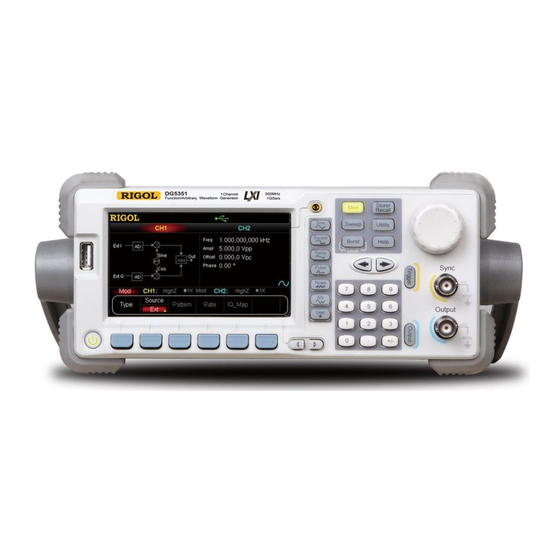
RIGOL Chapter 1 Quick Start User Interface The user interface is usually shown in two modes which are “Parameter” and “Graphic”. The illustration given here will take the “Graphic” mode of the Dual-Channel Model for example. Parameter Mode Figure 1-5 User Interface (Parameter Mode) Graph Mode In parameter mode, toggle the “Display Switch”... - Page 38 RIGOL Chapter 1 Quick Start 1. Status Bar Indicate system status. For example, an icon denotes that a USB flash device has been detected. 2. Current Function Show the current active function. For example, “Sine” denotes that sine wave has been selected at present.
-
Page 39: To Rack Mount The Instrument
RIGOL Chapter 1 Quick Start To Rack Mount the Instrument This generator can be mounted in a standard 19-inch rack cabinet. Please disassemble the cushioning material and handle before the installation. Kit Parts List Name Qty. Part Number Description Front Panel... -
Page 40: Installation Tool
RIGOL Chapter 1 Quick Start Installation Tool PH2 Phillips Screwdriver (recommended). Space Requirements for Installation The following requirements must be fulfilled by the machine cabinet in which the instrument is mounted. Dimension of the machine cabinet must be standard 19-inch. -
Page 41: Installation Procedures
RIGOL Chapter 1 Quick Start Installation Procedures Only authorized operators can execute the installation operation. The instrument will be damaged or installed in rack incorrectly if the installation is not proper. 1. Remove the handle: please grip the handle by sides, pull it outward and then upward. - Page 42 RIGOL Chapter 1 Quick Start 3. Place the instrument: align the protection pads of the instrument with the corresponding holes and then place it on the Support Board. 4. Fixed the instrument: Fasten the instrument tightly on the Support Board with two Fixed Figures and fixed it with four M4 screws.
- Page 43 RIGOL Chapter 1 Quick Start 6. Load into the machine cabinet: mount the rack fixed with instrument into a standard 19-inch machine cabinet with four M6 screws and square nuts. 7. Post-installation notice: The rack occupies a height of 3U. The holes pointed out by the arrows are the installation holes.
-
Page 44: To Use The Security Lock
RIGOL Chapter 1 Quick Start To Use the Security Lock Use a security lock to lock your generator in a desired location. As shown in the picture below, align the lock with the lock hole on the generator and insert the lock. Turn the key clockwise to lock the instrument and then pull the key out. -
Page 45: To Use The Built-In Help
8. Generate a Burst waveform. 9. IQ (In-Phase/Quadrature) modulation. 10. Frequency hopping output. 11. Storage management. 12. Synchronize multiple Generators. 13. Seamlessly connected with the RIGOL DS. 14. Get technical support from RIGOL. User’s Guide for DG5000 1-23 800.561.8187 information@itm.com www. - Page 46 800.561.8187 information@itm.com www. .com...
-
Page 47: Chapter 2 Basic Waveform Output
RIGOL Chapter 2 Basic Waveform Output Chapter 2 Basic Waveform Output This chapter introduces how to output basic waveforms such as Sine, Square, etc. The generator can output basic waveforms from the single channel or two channels at the same time. -
Page 48: To Output Sine Waveform
RIGOL Chapter 2 Basic Waveform Output To Output Sine Waveform To output a sine waveform from CH1 with 20 kHz frequency, 2.5 Vpp amplitude, 500 offset and 10 ° start phase. 1. Select Channel Press CH1|CH2 to select CH1. “CH1” in Channel Label Bar will be highlighted indicating that CH1 has been selected. - Page 49 RIGOL Chapter 2 Basic Waveform Output to input “500” and select the unit “mV ” in the pop-up menu. The offset range is limited by the “Resistance” and “Ampl/HoLevel” setting. Please refer to the “Output Characteristic” described in “Specifications”.
- Page 50 RIGOL Chapter 2 Basic Waveform Output Units Switching You can quickly switch the output unit of the current parameters from the front panel. For example, to transform 2 Vpp to a value whose unit is Vrms, press the key · in the numeric keyboard and then select the unit “Vrms” in the pop-up menu.
-
Page 51: To Output Square Waveform
RIGOL Chapter 2 Basic Waveform Output To Output Square Waveform To output a square waveform from CH1 with 20 kHz frequency, 2.5 Vpp amplitude, 500 mV offset, 30% duty cycle and 10 ° start phase. Refer to “To Output Sine Waveform”... -
Page 52: To Output Ramp Waveform
RIGOL Chapter 2 Basic Waveform Output To Output Ramp Waveform To output a ramp waveform from CH1 with 20 kHz frequency, 2.5 Vpp amplitude, 500 offset, 80% symmetry and 10 ° start phase. Refer to “To Output Sine Waveform” to configure the parameters and output. This section will only talk about “Symmetry”. -
Page 53: To Output Pulse Waveform
RIGOL Chapter 2 Basic Waveform Output To Output Pulse Waveform To output a pulse waveform from CH1 with 20 kHz frequency, 2.5 Vpp amplitude, 500 offset, 10 μs pulse width (20% duty cycle), 50 ns leading and trailing edge time and 8 μs delay. - Page 54 RIGOL Chapter 2 Basic Waveform Output Leading/Trailing Edge Time The Leading (rising) edge time is defined as the duration of the pulse amplitude rising from 10% to 90% threshold, while the Trailing (falling) edge time is defined as the duration of the pulse amplitude moving down from 90% to 10% threshold.
- Page 55 RIGOL Chapter 2 Basic Waveform Output Recover Delay The recover delay function is only for dual-channel models. Press Pulse, then use to open the 2/2 menu page and press Restore, the generator will align the delay between the two channels. Assume that CH1 and CH2 output pulse waveforms with the same parameters.
-
Page 56: To Output Noise Waveform
RIGOL Chapter 2 Basic Waveform Output To Output Noise Waveform To output noise waveform from CH1 with 2.5 Vpp amplitude and 500 mV offset. Refer to “To Output Sine Waveform” to configure the parameters and output. User’s Guide for DG5000 2-10 800.561.8187... -
Page 57: Align Phase
RIGOL Chapter 2 Basic Waveform Output Align Phase The align phase function is only for dual-channel models. Aligning phase is available for the operation of two channels. Pressing down this softkey will re-configure the two channels, and enable the generator to output with specified frequency and start phase. - Page 58 RIGOL Chapter 2 Basic Waveform Output NOTE: For dual-channel models, the Align Phase menu is grayed and disabled when any one of the two channels is in modulation mode. User’s Guide for DG5000 2-12 800.561.8187 information@itm.com www. .com...
-
Page 59: Chapter 3 Arbitrary Waveform Output
RIGOL Chapter 3 Arbitrary Waveform Output Chapter 3 Arbitrary Waveform Output This chapter introduces how to output built-in or user-defined arbitrary waveforms. The generator enable to output arbitrary waveforms from the single channel or two channels at the same time. -
Page 60: To Enable Arbitrary Waveform
RIGOL Chapter 3 Arbitrary Waveform Output To Enable Arbitrary Waveform Press Arb to open the operation menu of arbitrary waveform. 1. Freq/Period (Sample) Set the output “Frequency/Period” of the arbitrary waveform in “Normal” mode. Set the sample rate when the generator sample data from external memory in “Play”... - Page 61 RIGOL Chapter 3 Arbitrary Waveform Output Refer to “To Output Sine Waveform” to configure the parameters and output. This chapter will focus on “Mode”, “Sample”, “Select Waveform”, “Create New” and “Edit Waveform”. User’s Guide for DG5000 800.561.8187 information@itm.com www. .com...
-
Page 62: Output Mode
RIGOL Chapter 3 Arbitrary Waveform Output Output Mode Press Arb Mode to set arbitrary waveform output mode to “Normal” or “Play”. The generator adopts DDS to generate waveform data in “Normal” mode. In this case, you can change the phase step of the sampling by changing the Frequency (Period). -
Page 63: Play Mode
RIGOL Chapter 3 Arbitrary Waveform Output Play Mode The generator will enable the “Play” mode once the points of the arbitrary waveform to be output is greater than 16 Mpts and be able to output waveform with up to 128 Mpts. -
Page 64: To Select Arbitrary Waveform
RIGOL Chapter 3 Arbitrary Waveform Output To Select Arbitrary Waveform Press Arb, use to open the 2/2 menu page, and then press Select Wform to select “Builtin”, “Stored Wforms” or “Volatile Wform” for arbitrary waveform output. Built-In Waveform 10 kinds of built-in arbitrary waveforms are provided by DG5000, including DC, Sinc, Exponential Rise, Exponential Fall, ECG, Gauss, Haversine, Lorentz, Pulse and Dual Tones. - Page 65 RIGOL Chapter 3 Arbitrary Waveform Output Exponential Rise The figure below shows an Exponential Rise waveform. Exponential Fall The figure below shows an Exponential Fall waveform. The figure below shows an ECG waveform. User’s Guide for DG5000 800.561.8187 information@itm.com www.
- Page 66 RIGOL Chapter 3 Arbitrary Waveform Output Gauss The figure below shows a Gauss waveform. Haversine The figure below shows a Haversine waveform. Lorentz The figure below shows a Lorentz waveform. User’s Guide for DG5000 800.561.8187 information@itm.com www. .com...
- Page 67 RIGOL Chapter 3 Arbitrary Waveform Output Pulse The figure below shows a simulated Pulse waveform. The Pulse mentioned here can be configured by setting the parameters “Pulse Width/Duty Cycle”, “Leading” and “Trailing”. Pulse Width/Duty Cycle: The minimum Pulse Width is related to the current edge ...
- Page 68 RIGOL Chapter 3 Arbitrary Waveform Output Dual Tones The Dual Tones signal can be used to measure the inter-modulation distortion characteristic of non-linear devices (such as mixer or amplifier). Inter-Modulation Distortion (IMD) will be generated when a non-linear device with multiple input frequencies disturbs the adjacent channels or causes unexpected output at other frequencies.
-
Page 69: Stored Waveform
RIGOL Chapter 3 Arbitrary Waveform Output Stored Waveform Select arbitrary waveforms stored in internal non-volatile memory (C Disk) or external memories (D Disk or E Disk). Press this softkey to enter the Store/Recall Interface and the Store/Recall key on the front panel is illuminated. Please select and read the desired arbitrary waveform file. -
Page 70: To Create New Arbitrary Waveform
RIGOL Chapter 3 Arbitrary Waveform Output To Create New Arbitrary Waveform Press Arb, use to open the 2/2 menu page, and then press Create New to open the arbitrary waveform create interface. 1. Cycle Period Press this softkey and use the numeric keyboard or knob to set the cycle period of the new waveform. - Page 71 RIGOL Chapter 3 Arbitrary Waveform Output Sinc: The waveform editor will automatically connect the two points with a smooth curve. Notice that, the interpolation point voltage may be without the arbitrary waveform level limit and an unexpected curve will be acquired if the defined point voltage is the same as High VLimit or Low VLimit.
- Page 72 RIGOL Chapter 3 Arbitrary Waveform Output connect the start and end points using the current interpolation method. Note that point 1 cannot be deleted. 8. Save The currently created waveform is stored in the volatile memory. When creating a new waveform, the previous waveform in volatile memory will be overwritten.
-
Page 73: Edit Points
RIGOL Chapter 3 Arbitrary Waveform Output Edit Points The following example introduces how to create an arbitrary waveform which meets with the following conditions by using “Edit Points”. Parameter Value Cycle Period 12 μs High VLimit Low VLimit -2 V... - Page 74 RIGOL Chapter 3 Arbitrary Waveform Output use the numeric keyboard to input “0” and select the unit “V” in the pop-up menu. Press PointID again and use the numeric keyboard or knob to select point 2. Then press Time and Voltage respectively to define point 2 as 4 μs and 4 V.
-
Page 75: Edit Block
RIGOL Chapter 3 Arbitrary Waveform Output Edit Block The following example introduces how to create an arbitrary waveform which meets the following conditions with the following conditions met by using “Edit Block”. Parameter Value Cycle Period 12 μs High VLimit... - Page 76 RIGOL Chapter 3 Arbitrary Waveform Output automatically use straight lines to connect the start point (point 2, the level is 4 V) with the stop point (point 4, the level is -2 V) and automatically generate point 1 and point 3 to create a continuous waveform.
-
Page 77: To Edit Arbitrary Waveform
RIGOL Chapter 3 Arbitrary Waveform Output To Edit Arbitrary Waveform Arbitrary waveforms stored both in volatile memory and non-volatile memories can be recalled and re-edited. Press Arb and use to open the 2/2 menu page, then press Edit Wform to open waveform editing menu. - Page 78 800.561.8187 information@itm.com www. .com...
-
Page 79: Chapter 4 Common Modulation Output
RIGOL Chapter 4 Common Modulation Output Chapter 4 Common Modulation Output DG5000 can output versatile modulated waveforms with modulation types of analog modulation (AM, FM, PM), digital modulation (ASK, FSK, PSK) and pulse modulation (PWM). The generator provides a variety of internal modulating waveform sources and also accepts external modulating signal from [Mod In] or [ExtTrig] connector at the rear panel. -
Page 80: Amplitude Modulation (Am)
RIGOL Chapter 4 Common Modulation Output Amplitude Modulation (AM) An AM (Amplitude Modulation) modulated waveform consists of carrier waveform and modulating waveform. The amplitude of the carrier waveform varies with the instantaneous voltage of the modulating waveform. To Select AM Modulation Press Mod ... -
Page 81: To Select Modulating Waveform Source
RIGOL Chapter 4 Common Modulation Output To Select Modulating Waveform Source Press Mod Source to select “Int” or “Ext” modulating waveform source. 1. Internal Source When internal modulation source is selected, press Shape to select Sine, Square, Triangle, UpRamp, DnRamp, Noise or Arb as modulating waveform. The default is Sine. -
Page 82: To Set Modulation Depth
RIGOL Chapter 4 Common Modulation Output default value is 100 Hz. Notice that, this menu will be grayed out and disabled when external modulation source is selected. To Set Modulation Depth Modulation depth expressed as a percentage indicates the amplitude vibration degree. -
Page 83: Frequency Modulation (Fm)
RIGOL Chapter 4 Common Modulation Output Frequency Modulation (FM) A FM (Frequency Modulation) modulated waveform consists of carrier waveform and modulating waveform. The frequency of the carrier waveform varies with the instantaneous voltage of the modulating waveform. To Select FM Modulation Press Mod ... -
Page 84: To Select Modulating Waveform Source
RIGOL Chapter 4 Common Modulation Output To Select Modulating Waveform Source Press Mod Source to select “Int” or “Ext” modulating waveform source. 1. Internal Source When internal modulation source is selected, press Shape to select Sine, Square, Triangle, UpRamp, DnRamp, Noise or Arb as modulating waveform. The default is Sine. -
Page 85: To Set Frequency Deviation
RIGOL Chapter 4 Common Modulation Output To Set Frequency Deviation Press Deviation to set the frequency deviation of the modulating waveform frequency relative to the carrier waveform frequency. The frequency deviation must be less than or equal to the carrier waveform ... -
Page 86: Phase Modulation (Pm)
RIGOL Chapter 4 Common Modulation Output Phase Modulation (PM) A PM (Phase Modulation) modulated waveform consists of carrier waveform and modulating waveform. The phase of the carrier waveform varies with the instantaneous voltage of the modulating waveform. To Select PM Modulation Press Mod ... -
Page 87: To Select Modulating Waveform Source
RIGOL Chapter 4 Common Modulation Output To Select Modulating Waveform Source Press Mod Source to select “Int” or “Ext” modulating waveform source. 1. Internal Source When internal modulation source is selected, press Shape to select Sine, Square, Triangle, UpRamp, DnRamp, Noise or Arb as modulating waveform. The default is Sine. -
Page 88: To Set Phase Deviation
RIGOL Chapter 4 Common Modulation Output default value is 100 Hz. Notice that, this menu will be grayed out and disabled when external modulation source is selected. To Set Phase Deviation Press Deviation to set the deviation of the modulating waveform phase relative to the carrier waveform phase. -
Page 89: Amplitude Shift Keying (Ask)
RIGOL Chapter 4 Common Modulation Output Amplitude Shift Keying (ASK) When using ASK (Amplitude Shift Keying) modulation, you can configure the generator to make its output amplitude “shift” between two preset amplitude values (“carrier amplitude” and “modulating amplitude”). The “shift” rate (ASK Rate) is determined by the signal level inside the instrument or from the [ExtTrig] connector at the rear panel. -
Page 90: To Select Modulating Waveform Source
RIGOL Chapter 4 Common Modulation Output To Select Modulating Waveform Source Press Mod Source to select “Int” or “Ext” modulating waveform source. 1. Internal Source When internal source is selected, the modulating waveform is set as a Square with 50% duty cycle, and the “shift”... -
Page 91: To Set Modulating Amplitude
RIGOL Chapter 4 Common Modulation Output To Set Modulating Amplitude Press ModAmp to set the modulating amplitude. Input the desired amplitude value using numeric keyboard or knob. The available amplitude (High Z) ranges from 0 V to 10 V, and the default value is ... -
Page 92: Frequency Shift Keying (Fsk)
RIGOL Chapter 4 Common Modulation Output Frequency Shift Keying (FSK) When FSK (Frequency Shift Keying) modulation is selected, you can configure the generator to make its output frequency “shift” between two preset frequencies (“carrier frequency” and “hop frequency”). The “shift” frequency (FSK Rate) is determined by the signal level inside the instrument or from the [ExtTrig] connector at the rear panel. -
Page 93: To Select Modulating Waveform Source
RIGOL Chapter 4 Common Modulation Output To Select Modulating Waveform Source Press Mod Source to select “Int” or “Ext” modulating waveform source. 1. Internal Source When internal source is selected, the modulating waveform is set as a Square with 50% duty cycle, and the “shift”... -
Page 94: To Set Hop Frequency
RIGOL Chapter 4 Common Modulation Output To Set Hop Frequency The maximum alternating frequency (“hop” frequency) depends on the current selected carrier waveform. Press HopFreq to highlight it, input the desire frequency value using numeric keyboard or knob. Sine: 1 μHz to 250 MHz ... -
Page 95: Phase Shift Keying (Psk)
RIGOL Chapter 4 Common Modulation Output Phase Shift Keying (PSK) When PSK (Phase Shift keying) modulation is selected, you can configure the generator to make its output phase “shift” between two preset phase values (“carrier phase” and “modulating phase”). The “shift” frequency (PSK Rate) is determined by the signal level inside the instrument or from the rear panel [ExtTrig] connector at the rear panel. -
Page 96: To Set Psk Rate
RIGOL Chapter 4 Common Modulation Output 1. Internal Source When internal source is selected, the modulating waveform is set as a Square with 50% duty cycle, and the “shift” frequency at which the output phase shifts between “carrier phase” and “modulating phase” is determined by “PSK Rate”. -
Page 97: To Set Modulating Polarity
RIGOL Chapter 4 Common Modulation Output To Set Modulating Polarity Press Polarity to select the “Positive” or “Negative” of the modulating waveform to control the output phase. When internal modulation is selected, if the polarity is “positive”, logic low of the modulating waveform amplitude corresponds to carrier phase output and logic high corresponds to modulating phase output;... -
Page 98: Pulse Width Modulation (Pwm)
RIGOL Chapter 4 Common Modulation Output Pulse Width Modulation (PWM) A PWM (Pulse Width Modulation) modulated waveform consists of carrier waveform and modulating waveform. The pulse width of the carrier waveform varies with the instantaneous voltage of the modulating waveform. -
Page 99: To Select Modulating Waveform Source
RIGOL Chapter 4 Common Modulation Output To Select Modulating Waveform Source Press Mod Source to select “Int” or “Ext” modulating waveform source. 1. Internal Source When internal modulation source is selected, press Shape to select Sine, Square, Triangle, UpRamp, DnRamp, Noise or Arb as modulating waveform. The default is Sine. -
Page 100: To Set Modulating Waveform Frequency
RIGOL Chapter 4 Common Modulation Output To Set Modulating Waveform Frequency When internal modulation source is selected, press PWM Freq to set the frequency of the modulating waveform. Input the desire frequency value using numeric keyboard or knob. The available frequency ranges from 2 mHz to 50 kHz, and the default value is ... -
Page 101: Chapter 5 Iq Modulation Output
RIGOL Chapter 5 IQ Modulation Output Chapter 5 IQ Modulation Output This chapter introduces how to output IQ modulated waveform. DG5000 provides internal baseband source, and also accepts external I and Q modulating signals from the [Mod In/Q] connector at the rear panel. The modulated waveforms can be output from the single channel or the two channels at the same time. -
Page 102: Iq Modulation Overview
RIGOL Chapter 5 IQ Modulation Output IQ Modulation Overview In IQ modulation, two orthogonal signals (carrier waveforms with the same frequency and 90 ° phase difference, usually expressed as Sin and Cos) modulate with two signals, I (In-Phase, in-phase component) and Q (Quadrature Phase, quadrature component) respectively, and then are transmitted together to improve the frequency spectrum efficiency. -
Page 103: To Select Iq Modulation
RIGOL Chapter 5 IQ Modulation Output To Select IQ Modulation Press Mod Type IQ to enable IQ modulation function. When Mod is enabled, Sweep or Burst will be disabled automatically (if enabled currently). After IQ is enabled, the instrument will generate IQ modulated waveform with ... - Page 104 RIGOL Chapter 5 IQ Modulation Output 2. External Source After the “external” source is selected, the generator accepts I and Q modulating signals from the rear panel [Mod In/I] and [Mod In/Q] connectors. And then, Pattern, Rate and IQ_Map menus will be grayed out and disabled.
-
Page 105: To Select Code Pattern
RIGOL Chapter 5 IQ Modulation Output To Select Code Pattern When internal modulation is selected, users could select the internal pre-defined or user-defined code patterns. Pre-defined PN Sequence Code Pattern PN sequence (Pseudo-noise Sequence, pseudo random noise sequence) is a periodic binary sequence approximation. -
Page 106: User-Defined Code Pattern
RIGOL Chapter 5 IQ Modulation Output User-defined Code Pattern User could edit code pattern with up to 2000 Words (4000 Bytes) in the user space provided by DG5000. In internal modulation mode, press Code Pattern User to open user-defined code pattern interface. - Page 107 RIGOL Chapter 5 IQ Modulation Output 2. Select Input Format Binary format or hex format can be used in data editing. Press InputTyp to select “binary format” or “hex format”, and the default is “hex format”. When “binary format” is selected, characters from 2 to F are not available. Note that, in address editing, if “binary format”...
-
Page 108: To Set Code Rate
RIGOL Chapter 5 IQ Modulation Output To Set Code Rate Users can set the transmission rate of the code. When internal modulation is selected, press Rate and use the numeric keyboard or knob to modify the value. The available range is from 1 bps to 1 Mbps, and the default value is 9600 kbps. -
Page 109: Iq Mapping
RIGOL Chapter 5 IQ Modulation Output IQ Mapping As mentioned before, IQ modulation vectorially bridges the digital signal and the analog signal. IQ mapping is the description of the function of the bridge. DG5000 provides versatile multilevel digital modulation types (4QAM, 8QAM, 16QAM, 32QAM, 64QAM, BPSK, QPSK, OQPSK, 8PSK, 16PSK). - Page 110 RIGOL Chapter 5 IQ Modulation Output to select the data to be edited, use the knob to change the corresponding value, and the unit is V by default. The setting range of each IQ component is from -1 V to 1 V.
- Page 111 RIGOL Chapter 5 IQ Modulation Output 4. 32QAM (32-Quadrature Amplitude Modulation) 5. 64QAM (64-Quadrature Amplitude Modulation) 6. BPSK (Binary Phase Shift Keying) User’s Guide for DG5000 5-11 800.561.8187 information@itm.com www. .com...
- Page 112 RIGOL Chapter 5 IQ Modulation Output 7. QPSK (Quadrature Phase Shift Keying) 8. OQPSK (Offset Quadra Phase Shift Keying) 9. 8PSK (8-Phase Shift Keying) User’s Guide for DG5000 5-12 800.561.8187 information@itm.com www. .com...
- Page 113 RIGOL Chapter 5 IQ Modulation Output 10. 16PSK (16- Phase Shift Keying) User’s Guide for DG5000 5-13 800.561.8187 information@itm.com www. .com...
- Page 114 800.561.8187 information@itm.com www. .com...
-
Page 115: Chapter 6 Frequency Sweep Output
RIGOL Chapter 6 Frequency Sweep Output Chapter 6 Frequency Sweep Output DG5000 could output Sweep waveform from the single channel or the two channels at the same time. In Sweep mode, the generator outputs the signal variably from Start Frequency to End Frequency within the specified Sweep time. The generator supports sweeping from low to high frequency or from high to low frequency and supports three sweep types: Linear, Log and Step. -
Page 116: To Enable Frequency Sweep
RIGOL Chapter 6 Frequency Sweep Output To Enable Frequency Sweep Press Sweep at the front panel to enable Sweep function (the backlight of the key goes on), and Mod or Burst function will be automatically disabled (if currently enabled). The instrument will generate the specified sweep waveform from corresponding channel according to the current configuration. -
Page 117: Center Frequency And Frequency Span
RIGOL Chapter 6 Frequency Sweep Output Center Frequency and Frequency Span You can also set the frequency boundaries of frequency sweep through center frequency and frequency span. Center Frequency = (|Start Frequency + End Frequency|) / 2 Frequency Span = End Frequency – Start Frequency ... -
Page 118: Sweep Type
RIGOL Chapter 6 Frequency Sweep Output Sweep Type DG5000 provides three sweep types, including Linear, Log and Step, and the default is Linear. Linear Sweep The output frequency of the instrument varies linearly in the way “several Hertz per second”. The variation is controlled by “Start Frequency”, “End Frequency” and “Sweep Time”. -
Page 119: Log Sweep
RIGOL Chapter 6 Frequency Sweep Output Log Sweep The output frequency of the instrument varies in a logarithmic fashion, that is, the output frequency changes in the way of “octave per second” or “decade per second”. The change is controlled by “Start Frequency”, “End Frequency” and “Sweep Time”. -
Page 120: Step Sweep
RIGOL Chapter 6 Frequency Sweep Output Step Sweep The output frequency of the instrument is “stepping” from “Start Frequency” to “End Frequency”. The duration of the output signal on each frequency point is determined by “Sweep Time” and “Step Number”. -
Page 121: Sweep Time
RIGOL Chapter 6 Frequency Sweep Output Sweep Time When Sweep is enabled, press SwpTime and use the numeric keyboard or the knob to change the sweep time. The default value is 1 s and the available range is from 1 ms to 300 s. -
Page 122: Start Hold
RIGOL Chapter 6 Frequency Sweep Output The generator will renewedly sweep and output with the specified “Start Frequency” once the Mark Frequency is changed. Start Hold Start Hold is the duration that the output signal outputs with the “Start Frequency”... -
Page 123: Sweep Trigger Source
RIGOL Chapter 6 Frequency Sweep Output Sweep Trigger Source The Sweep trigger source could be internal, external or manual source. The generator will generate a sweep output when a trigger signal is received and then wait for the next trigger. -
Page 124: Sweep Trigger Output
RIGOL Chapter 6 Frequency Sweep Output Sweep Trigger Output In Sweep mode, when “Internal” or “Manual” trigger source is selected, the generator will output a TTL compatible signal with specified polarity from the [ExtTrig] connector at the rear panel. Internal Trigger: the generator outputs a Square waveform with 50% duty cycle ... -
Page 125: Chapter 7 Burst Output
RIGOL Chapter 7 Burst Output Chapter 7 Burst Output DG5000 could output burst waveform from the single channel or the two channels at the same time. In Burst mode, the generator could output waveform with specified cycle number and could also output “Gated” burst using external gated signal. Sine, Square, Ramp, Pulse or arbitrary waveform (except Noise or DC) can be used to generate burst. - Page 126 800.561.8187 information@itm.com www. .com...
-
Page 127: Burst Type
RIGOL Chapter 7 Burst Output To Enable Burst Mode Press Burst at the front panel to enable Burst function (the backlight of the key goes on), and Mod or Sweep function will be automatically disabled (if currently enabled). The generator will output burst waveform from the corresponding channel according to the current configuration. - Page 128 RIGOL Chapter 7 Burst Output also set “Start Phase”, “Burst Period” (internal trigger), “Delay”, “Trigger Input” (external trigger) and “Trigger Output” (internal and manual triggers). User’s Guide for DG5000 800.561.8187 information@itm.com www. .com...
-
Page 129: Infinite Burst
RIGOL Chapter 7 Burst Output Infinite Burst In Infinite mode, the cycle number of the waveform is set as an infinite value. The generator outputs a continuous waveform after receiving trigger signal. Waveform functions which support Infinite Burst are Sine, Square, Ramp, Pulse and arbitrary waveforms (except Noise and DC). -
Page 130: Gated Burst
RIGOL Chapter 7 Burst Output Gated Burst In Gated Mode, the generator controls the output waveform according to the external signal from the [ExtTrig] connector at the rear panel (as shown in the picture below). Waveform functions which support Gated Burst are Sine, Square, Ramp, Pulse, Noise and arbitrary waveforms (except DC). -
Page 131: Burst Phase
RIGOL Chapter 7 Burst Output Burst Phase To define the start and end points of the burst waveform. When Burst is enabled, press Start Phase and then use the numeric keyboard or the knob to input the desired phase, the default value is 0 ° and the available range is from 0 °... -
Page 132: Burst Delay
RIGOL Chapter 7 Burst Output Burst Delay Defined as the time from when the generator receives the trigger signal to starts to output the N Cycle (or Infinite) burst. This parameter is for N cycle and infinite burst mode. When Burst is enabled, press Type “N_Cyc” or “Infinite” Delay and use the numeric keyboard or the knob to input the desired delay. -
Page 133: Burst Trigger Output
RIGOL Chapter 7 Burst Output 3. Manual Trigger A burst will be generated once you press the softkey menu Manual for dual-channel model or the key Trigger at the front panel for single channel model. Burst Trigger Output In Burst mode, when “Internal” or “Manual” trigger source is selected, the generator will output a TTL compatible signal with specified polarity from the [ExtTrig] connector at the rear panel. - Page 134 800.561.8187 information@itm.com www. .com...
-
Page 135: Chapter 8 Fh Output (Option)
RIGOL Chapter 8 FH Output (Option) Chapter 8 FH Output (Option) DG5000 could output Frequency Hopping (FH) waveform from the single channel or the two channels at the same time. If you want to use FH function, please install the relevant option first. -
Page 136: Fh Overview
RIGOL Chapter 8 FH Output (Option) FH Overview Traditional radio communication, which works at a fixed frequency, could easily be intercepted and electrically disturbed and the security is very poor. Frequency hopping (FH) is a spread spectrum technique which uses carrier waveform frequency hopping to realize spread frequency spectrum and is widely used in anti-interference communication system. -
Page 137: To Enable Fh Function
RIGOL Chapter 8 FH Output (Option) To Enable FH Function Press Utility CH1 Set (or CH2 Set), use to open the 2/2 menu page, press FreqHop to enable FH function for CH1 (or CH2). The FH function setting interface is shown below. -
Page 138: To Select Carrier Waveform
RIGOL Chapter 8 FH Output (Option) To Select Carrier Waveform As mentioned above, the allowed carrier waveform for FH is only Sine. To select Sine waveform, press Sine. If other waveform is selected, the generator will automatically turn off the FH ... -
Page 139: Display Type
RIGOL Chapter 8 FH Output (Option) to input the No. of the desired point, the available No. is limited by the current FH points (the point number of FH sequence) and the default is 1. The “Chess” or “Table” data on the screen will be updated and displayed once this parameter is changed. -
Page 140: To Load Map
RIGOL Chapter 8 FH Output (Option) To Load Map Users could load the stored FH map from internal or external memory of the instrument. When FH is enabled, press Load Map to select “BuiltIn”, “Stored” or “Volatile”. 1. Built-In Map 4 built-in FH maps (Map1, Map2, Map3 and Map4) are provided by DG5000. -
Page 141: To Edit Map
RIGOL Chapter 8 FH Output (Option) To Edit Map DG5000 permits users to define FH map and store the map in local or external memory. When FH is enabled, press Switch to select “Off”, and then press Edit Map. Users could edit the hopping frequency points of the carrier through “FH list” and control the hopping order of the carrier by editing “FH sequence”. - Page 142 RIGOL Chapter 8 FH Output (Option) To Edit List Press Edit List Edit Point to open the list editing interface. 1. Press Current Point, use the numeric keyboard or the knob to input the No. of the point to be edited (i.e. n in the figure above), and this No. is limited by the points of the current list.
-
Page 143: Fh Sequence
RIGOL Chapter 8 FH Output (Option) FH Sequence As shown in the figure above, if there are 8 frequencies available in a FH system expressed as numbers from 1 to 8, then {8,1,2,4,6,3,5,7,6,1,2} is a simple FH sequence. The sequence determines that the output sequence of the frequency is Figure 8-4 FH Sequence in FH Map 1. -
Page 144: To Save Fh Map
RIGOL Chapter 8 FH Output (Option) To Edit Sequence Press Edit Sequence Edit Point to open the Sequence Editing Interface. 1. Press Current Point, use the numeric keyboard or the knob to input the No. of the point to be edited (i.e. n in the figure above), and the No. is limited by the points number of the current sequence. -
Page 145: Chapter 9 Store And Recall
RIGOL Chapter 9 Store and Recall Chapter 9 Store and Recall This chapter introduces how to store and recall waveform data or the instrument state. Subjects in this chapter: Storage System Overview To Select File Type To Select Browser Type ... -
Page 146: Storage System Overview
RIGOL Chapter 9 Store and Recall Storage System Overview DG5000 could store the current instrument state or waveform data in local or external memory and recall them when needed. DG5000 provides a local and two external directories. The local directory is “C Disk”... -
Page 147: To Select File Type
RIGOL Chapter 9 Store and Recall character (including number and underline) only. If you use other characters to name the file and file holder, the Store and Recall interface could not display it normally. To Select File Type The status to be stored includes the waveform shape, frequency, amplitude, DC offset, duty cycle, symmetry, phase of the two channels and any other parameters of Mod, Sweep or Burst. -
Page 148: To Select Browser Type
RIGOL Chapter 9 Store and Recall To Select Browser Type Press Store/Recall Browser to switch “Dir” or “File”. Use the knob to select the desired directory or file and use the direction keys to fold or unfold the directory. - Page 149 RIGOL Chapter 9 Store and Recall 3. To Input Filename Press InType to select “Chinese” or “English” input type. The length of the file or folder name is limited within 32 characters. English Inputting (including number inputting): Press +/- on the numeric keyboard to switch uppercase/lowercase.
- Page 150 RIGOL Chapter 9 Store and Recall select the No. of the desired Chinese character in the “Chinese Character Display Area” and the selected character will be displayed in “Filename Inputting Area”. Use the same method to input all the desired Chinese characters of the filename.
-
Page 151: To Recall A File
RIGOL Chapter 9 Store and Recall To Recall a File 1. To Select File Type Select the file type to be recalled following the introduction in “To Select File Type”. Notice, if the current file type is “All File”, the file to be recalled is the currently selected file. -
Page 152: To Paste A File
RIGOL Chapter 9 Store and Recall To Paste a File 1. To Copy a File Copy a file following the introduction in “To Copy a File”. 2. To Select Paste Destination Set Browser as “Dir” and use the knob to select a paste destination directory. -
Page 153: To Create A New Folder
RIGOL Chapter 9 Store and Recall To Create a New Folder 1. To Select Browser In Store/Recall interface, set Browser as “File”, use to open the 2/2 menu page and press New Directory to enter the folder name inputting interface as shown below. -
Page 154: Seamlessly Interconnection
RIGOL Chapter 9 Store and Recall Seamlessly Interconnection DG5000 could interconnect with RIGOL oscilloscope which supports USB-TMC seamlessly and rebuilt and output the waveform data collected from the oscilloscope lossless. USB Cable BNC Cable DG5000 USB Device USB Host OUTPUT INPUT 1. -
Page 155: Chapter 10 Advanced Operation
RIGOL Chapter 10 Advanced Operation Chapter 10 Advanced Operation This chapter introduces the advanced operations of the generator including system parameters setting, waveform saving and printing, function expansion and the remote control interfaces configuration. Subjects in this chapter: Advanced Operation Overview ... -
Page 156: Advanced Operation Overview
RIGOL Chapter 10 Advanced Operation Advanced Operation Overview Press Utility at the front panel to open the advanced operation interface as shown below. The interface presents the current output configurations of the channels, GPIB address, Clock Source, Base Source and Frequency/Phase Deviation of Channel Coupling, Language and Power On value. -
Page 157: Channel Setting
RIGOL Chapter 10 Advanced Operation Channel Setting This section takes CH1 for example to illustrate how to set the channel. The setting method for CH2 is quite the same. Sync Setting DG5000 could output the sync signals of basic waveform (except Noise and DC),... - Page 158 RIGOL Chapter 10 Advanced Operation For AM, FM, PM, PWM and IQ, in internal modulation mode, the sync signal is a Square with 50% duty cycle and takes modulating frequency as reference. It is TTL high level in the first half period of the modulation waveform. In external mode, the sync signal is a Square with 50% duty cycle and takes the carrier waveform as reference.
-
Page 159: Sync Polarity
RIGOL Chapter 10 Advanced Operation Sync Polarity Set the sync signal on the [Sync] connector as normal or invert. Press Utility CH1 Set Polarity to select “Positive” or “Negative”. Notice that the sync signal related to the waveform is not invert even when the waveform is invert. -
Page 160: Resistance Setting
RIGOL Chapter 10 Advanced Operation Resistance Setting Resistance setting is applied to output amplitude and voltage offset. For [Output] connector on the front panel, DG5000 provides a 50 Ω fixed series-connected output resistance. If the real load is different from the specified value, the displayed voltage level will not match with the voltage of the measured device. -
Page 161: Attenuation Setting
RIGOL Chapter 10 Advanced Operation Attenuation Setting This setting will attenuate (amplifier) the current amplitude following specified ratio and output the waveform. The available attenuation ratios include 1X, 2X, 5X and 10X. Press Utility CH1Set Attenuat to select desired ratio. -
Page 162: Channel Coupling
RIGOL Chapter 10 Advanced Operation Channel Coupling The dual-channel model of DG5000 supports coupling output of frequency or phase. When coupling is enabled, set CH1 or CH2 as the “base” channel and set the frequency or phase deviation of the two channels. Then when the frequency or phase of the base channel is changed, the corresponding parameter of the other channel will change automatically and always keeps the specified frequency or phase deviation. - Page 163 RIGOL Chapter 10 Advanced Operation Key Points: Coupling is valid only when all the two channels are in basic waveforms (Sine, Square, Ramp or arbitrary waveform) mode. But when the arbitrary waveform is “DC”, the coupling is invalid. If the sum of the frequency or phase of the base channel and the specified ...
-
Page 164: Channel Copy
RIGOL Chapter 10 Advanced Operation Channel Copy DG5000 dual-channel model supports parameters copy between its two channels. Channel copy function enables to copy the parameters (such as waveform shape, frequency and amplitude) and output setting (e.g. resistance and polarity) of one channel to the other channel. -
Page 165: System Setting
RIGOL Chapter 10 Advanced Operation System Setting Number Format You could set the display format of decimal point and thousands separator in number parameters on the screen. The setting is stored in nonvolatile memory. Press Utility System Number Format to enter the number format setting interface. -
Page 166: Language
RIGOL Chapter 10 Advanced Operation Language At present, DG5000 supports Chinese/English Menu, Help, Interface and Input Method. Press Utility System Language to select the desired language. The setting is stored in nonvolatile memory and will not be influenced by “Preset”. - Page 167 RIGOL Chapter 10 Advanced Operation Interface Mode Parameter Output Terminal 50 Ω Sync Output Range Setting Auto Sync Polarity Positive Output Polarity Normal Attenuation Setting Coupling Switch Coupling Base Coupling Type Frequency Deviation Phase Deviation 0° Frequency Deviation 0 Hz...
- Page 168 RIGOL Chapter 10 Advanced Operation Display Type Chessboard Map Type Map1 FH Interval 10 ms Start Point AM Modulation Modulating Source Internal Modulating Waveform Sine AM Frequency 100 Hz Modulation Depth 100% FM Modulation Modulating Source Internal Modulating Waveform Sine...
- Page 169 RIGOL Chapter 10 Advanced Operation FSK Modulation Modulating Source Internal FSK Rate 100 Hz Hop Frequency 10 kHz FSK Polarity Positive PSK Modulation Modulating Source Internal PSK Rate 100 Hz PSK Phase 180° PSK Polarity Positive IQ Modulation Modulating Source...
- Page 170 RIGOL Chapter 10 Advanced Operation Cycle Number 1 Cycle Initial Phase 0° Burst Delay Gated Polarity Positive Trigger Source Internal Trigger Output Trigger Input Leading Trigger Period 10 ms System Parameter DHCP Auto IP Manual IP Beep Power On Setting...
-
Page 171: Display Setting
RIGOL Chapter 10 Advanced Operation Display Setting You could set the screen brightness and the background color of the selected parameter or menu for DG5000. Press Utility System Display to enter the Display setting interface. 1. Brightness Setting Press Light and use the knob to change the brightness. -
Page 172: Beep Setting
RIGOL Chapter 10 Advanced Operation Beep Setting Enable or disable the beep caused by front panel operation or error message from remote interface. Press Utility System Beep to select “On” or “Off”. The default is “On”. The current selection is stored in nonvolatile memory. -
Page 173: Clock Source Setting
RIGOL Chapter 10 Advanced Operation Clock Source Setting DG5000 provides a 10 MHz internal clock source and also accepts external clock source input from the [10MHz In] connector at the rear panel. It can also output a 10 MHz clock source from the [10MHz Out] connector for other device to use. - Page 174 RIGOL Chapter 10 Advanced Operation Synchronization among multi-instruments (Method 2): Divide the 10 MHz clock source of a Generator (“Internal” clock) into multiple channels, and then connect them to the [10 MHz In] connectors of other generators (“External” clock) respectively, and finally set the output frequencies of all the generators as a same value to realize synchronization for multi-instruments.
-
Page 175: User-Defined Shortcut
RIGOL Chapter 10 Advanced Operation User-defined Shortcut The User* key at the front panel provides a shortcut for users. You could define it as your desired function which can be recalled once you press the key in any operation interface. -
Page 176: Print
Switching the screen to your desired image within the specified time, the generator will automatically store the image under the folder named “Rigol” (created automatically if it do not exist) in the USB flash device in bitmap form (*.BMP). If the storage operation succeeds, the screen will display corresponding prompt message. -
Page 177: Test Calibration
Press Utility Test/Cal to open test calibration interface. Users could execute self-test and examine calibration information. Self-calibration by users is not recommended. If the instrument needs to be calibrated, please contact RIGOL. 1. Self Test After pressing this key, the instrument executes self-test. The operation lasts about 3 s. -
Page 178: To Use The Power Amplifier (Option)
Amplifier (PA), which can amplify and then output the signal. To use external power amplifier, please install the PA1011 option. PA1011 is one of the options provided for RIGOL DG Series Function/Arbitrary Waveform Generators, with up to 1 MHz full power bandwidth and higher than 80 V/µs slew rate. - Page 179 RIGOL Chapter 10 Advanced Operation Front Panel: Status Indicator Signal Output Signal Input Status Indicator Power: red light on, indicating successful power connection. Output: green light on, indicating that output is turned on. Link: yellow light on, indicating successful USB connection.
- Page 180 RIGOL Chapter 10 Advanced Operation Rear Panel: USB Device Power In Fan Aperture CAUTION Do not use any other adapters to supply power for the PA1011, or else it may cause degradation or perpetual damage. CAUTION Please make sure the vents at both sides and the fan aperture at the rear panel are visible in operation for normal working.
- Page 181 RIGOL Chapter 10 Advanced Operation Connect DG5000 with PA1011: Output BNC Cable Input PA1011 DG5000 USB Host USB Cable USB Device Output When the connection succeeds, press Utility PA Setup to open the PA parameters setting interface. 1. ON/OFF Press this key to turn “On”...
-
Page 182: To Use The Digital Module (Option)
To use digital output, please install the DG-POD-A option. DG-POD-A is a logical signal output module matching for RIGOL DG series Function/Arbitrary Waveform Generators, with external 16-channel data outputs and 2-channel clock outputs, making DG5000 series real Mixed Signal Generator (MSG). - Page 183 RIGOL Chapter 10 Advanced Operation Appearance and Input/output Ports: Indicator Light of the Digital Logic Output Digital Input Indicator Light of the Analog Output Indicator Light of the Digital Logic Output Definitions of Analog Output Ports: CLK1 CLK0 User’s Guide for DG5000 10-29 800.561.8187...
- Page 184 RIGOL Chapter 10 Advanced Operation DG-POD-A Accessories: Name Qty. Description Data Flat Cable Connect DG5000 and DG-POG-A. SMB-to-SMA RF Coaxial Lines Connect the digital logic output with the device under test. Logic Analyzer Testing Lines Connect the analog output with the device under test.
-
Page 185: Protocol Setting
RIGOL Chapter 10 Advanced Operation Protocol Setting Press Config to open the protocol setting menu. For different protocols, different parameters are to be set. 1. RS232 Protocol Setting When “RS232” protocol is currently selected, press Config to open the corresponding setting menu. - Page 186 RIGOL Chapter 10 Advanced Operation range available is from 1bps to 60Mbps. Press CSLevel to select L or H, wherein, L represents low level and H represents high level. 3. IIC Protocol Setting When “IIC” protocol is currently selected, press Config to open the corresponding setting menu.
- Page 187 RIGOL Chapter 10 Advanced Operation Press BitOrder to select LSB or MSB. The bit order of data output depends on the protocol selected. RS232 protocol always uses LSB order, SPI and IIC protocols always use MSB order, while PO protocol can use LSB or MSB.
-
Page 188: To Set The Code Pattern
RIGOL Chapter 10 Advanced Operation To Set the Code Pattern Press Pattern to select the code pattern of the output data: ALL_0, ALL_1, 01, 8PRBS (Pseudo Random Binary Sequence), 16PRBS, 32PRBS or User (user-defined code pattern). When “User” is selected, users can also set the starting Offset of the data output. The range of the offset is from 0 to 262143 Bytes. -
Page 189: User Data Editing
RIGOL Chapter 10 Advanced Operation User Data Editing Press DataEdt to open the digital waveform editing interface (for editing method, refer to “User-defined Code Pattern”). Users can edit up to 131072 Words (262144 Bytes) of data. Note the user-edited data can be output only when the code pattern is set to “User”. -
Page 190: To Set The Output Data Length
RIGOL Chapter 10 Advanced Operation To Set the Output Data Length Press Length and use the knob or the number keypad to set the output data length. Output data length under different protocol has different upper limit. If the current... -
Page 191: Channel Setting
RIGOL Chapter 10 Advanced Operation Channel Setting Press Channel to open the channel setting menu of the selected protocol. Different parameters are to be set for different protocols. The module provides 16 data channels and 2 clock channels. Users can select the desired data channel and clock channel and set the channel voltage. - Page 192 RIGOL Chapter 10 Advanced Operation voltage is automatically adjusted to be 3/8 of analog channel voltage. While, when adjusting digital channel voltage, analog channel voltage is automatically set to the same value as digital channel voltage. 3. Channel Setting under IIC Protocol When “IIC”...
-
Page 193: Trigger Setting
RIGOL Chapter 10 Advanced Operation Press DigitCh to select the digital channel voltage of the digital module: 1.8V, 2.5V, 3.3V, 4.0V, User or Off. When “User” is selected, the range available is from 1.4V to 4.2V. Press AnalogCh to select On or Off. When On is selected, the analog channel ... -
Page 194: To Configure The Remote Interface
RIGOL Chapter 10 Advanced Operation To Configure the Remote Interface DG5000 is furnished with USB, GPIB (IEEE-488) and LAN interface and enables to access the I/O configuration parameters using for remote control from GPIB or LAN interface (USB parameters needn’t to be configured). - Page 195 RIGOL Chapter 10 Advanced Operation Network Status Different promote messages will be provided by DG5000 based on the current network status. Connected: LAN connection is successful. Disconnect: LAN connection is unsuccessful. MAC Address For a generator, the MAC address is always unique. It is always used to identify the instrument while assigning IP address for instrument.
- Page 196 RIGOL Chapter 10 Advanced Operation Press ManualIP to select “On” or “Off” to turn ManualIP mode on or off. To enable this mode, set DHCP and AutoIP as “Off”. The IP format is nnn.nnn.nnn.nnn. The first nnn ranges from 0 to 223 ...
- Page 197 RIGOL Chapter 10 Advanced Operation To Set Subnet Mask In ManualIP mode, the subnet mask could be manually set. The format of subnet mask is nnn.nnn.nnn.nnn, where nnn ranges from 0 to 255. We recommend that users acquire an available subnet mask from your network administrator.
- Page 198 RIGOL Chapter 10 Advanced Operation Press Host Name and use the numeric keyboard and direction keys to enter the host name, with up to 16 length, which could consist of letters, numbers, dot and dash. The setting is stored in the non-volatile memory.
-
Page 199: To Set Usb Device Type
RIGOL Chapter 10 Advanced Operation To Set USB Device Type As mentioned before, the USB Device interface at DG5000 rear panel could be connected with PC or PictBridge printer. When different devices are used, you need to configure the generator to match the currently connected device. - Page 200 800.561.8187 information@itm.com www. .com...
-
Page 201: Chapter 11 Remote Control
Programming Guide. Use PC software provided by RIGOL or other manufacturers Users can use the PC software Ultra Sigma (from RIGOL), Measurement & Automation Explorer (from National Instruments Corporation) or Agilent IO Libraries Suite (from Agilent Technologies, Inc.) to send commands to control DG5000 remotely. -
Page 202: Remote Control Via Usb
The status bar of Ultra Sigma at present is shown like the figure below: 4. View the resource The resources that have been searched successfully are shown in the “RIGOL Online Resource” catalog and the instrument model and USB information are also displayed as shown in the figure below. - Page 203 Chapter 11 Remote Control 5. Communicate Test Right click the resource name such as DG5352 (USB0::0x1AB1::0x0488::DG5000000000::INSTR) and select Instrument Common RIGOL SCPI ControlPanel V1 to open the interface below, from which you can send commands and read data. User’s Guide for DG5000 11-3 800.561.8187...
-
Page 204: Remote Control Via Lan
Ultra Sigma at present is shown like the figure below: 4. View the resource The resources that have been searched successfully are shown in the “RIGOL Online Resource” catalog, as shown in the figure below. 5. Communication test Right click the resource name such as DG5352 User’s Guide for DG5000... - Page 205 RIGOL Chapter 11 Remote Control (TCPIP::172.16.3.58::INSTR) and select Instrument Common RIGOL SCPI ControlPanel V1 to open the interface below, from which you can send commands and read data. 6. Load LXI webpage The generator conforms to LXI-Class standards. You can load LXI webpage conveniently through Ultra Sigma (right-clicking the resources name and selecting “LXI-Web”).
- Page 206 RIGOL Chapter 11 Remote Control User’s Guide for DG5000 11-6 800.561.8187 information@itm.com www. .com...
-
Page 207: Remote Control Via Gpib
RIGOL Chapter 11 Remote Control Remote Control Via GPIB 1. Connect the devices Connect the generator to your PC using GPIB cable. 2. Install the device driver of the GPIB card Install the driver of the GPIB card which has been connected to the PC correctly. - Page 208 Chapter 11 Remote Control 5. View the resource Click “OK” to return back to the main interface of Ultra Sigma. The resources that have been searched successfully at present are shown in the “RIGOL Online Resource” catalog. 6. Communication test...
-
Page 209: Chapter 12 Troubleshooting
(2) Check if the power switch is really on. (3) Restart the instrument after finishing the above inspections. (4) If it does not work correctly, contact RIGOL for our service. 2. The settings are correct but no waveform is generated:... - Page 210 800.561.8187 information@itm.com www. .com...
-
Page 211: Chapter 13 Specifications
The generator is within the calibration period and has performed self-calibration. The generator has been working continuously for 30 minutes at specified temperature (18°C ~ 28°C). All the specifications are guaranteed unless those marked with “typical”. Model DG5352/ DG5252/ DG5102/ DG5072/ DG5351 DG5251 DG5101... - Page 212 RIGOL Chapter 13 Specifications <-45dBc <-45dBc <-45dBc <-45dBc >100MHz: >100MHz: <-35dBc <-35dBc Total Harmonic <0.5% (10 Hz to 20 kHz, 0 dBm) Distortion Spurious Typical (0 dBm) Typical (0 dBm) Typical (0 dBm) Typical (0 dBm) (non-harmonic) ≤100MHz: ≤100MHz: ≤100MHz: ≤70MHz:...
- Page 213 RIGOL Chapter 13 Specifications Leading/ Typical Value Typical Value Typical Value Typical Value Trailing Edge (1Vpp, 50Ω) (1Vpp, 50Ω) (1Vpp, 50Ω) (1Vpp, 50Ω) Time 2.5 ns to 1 ms 2.5 ns to 1 ms 3 ns to 1 ms 4 ns to 1 ms...
- Page 214 RIGOL Chapter 13 Specifications Accuracy Typical (1 kHz Sine, 0 V Deviation, >10 mVpp, Auto) ± 1% of setting ± 1 mVpp Amplitude <10MHz: ±0.1dB <10MHz: ±0.1dB <10MHz: ±0.1dB <10MHz: ±0.1dB Flatness 10MHz to 60MHz: 10MHz to 60MHz: 10MHz to 60MHz:...
- Page 215 RIGOL Chapter 13 Specifications Carrier Sine, Square, Ramp, Arb (except DC) Waveforms Source Internal/External Modulating Sine, Square, Ramp, Noise, Arb (2 mHz to 50 kHz) Waveforms Depth 0% to 120% Carrier Sine, Square, Ramp, Arb (except DC) Waveforms Source Internal/External...
- Page 216 RIGOL Chapter 13 Specifications Modulating Square with 50% duty cycle (2 mHz to 1 MHz) Waveforms Carrier Pulse Waveform Source Internal/External Modulating Sine, Square, Ramp, Noise, Arb (2 mHz to 50 kHz) Waveforms Width 0% to 100% of Pulse Width...
- Page 217 RIGOL Chapter 13 Specifications Trigger Delay 0 ns to 85 s Sweep Characteristics Carrier Sine, Square, Ramp, Arb (except DC) Waveforms Type Linear, Log or Step Direction Up or Down Start/Stop 1 μHz to 250 MHz 1 μHz to 250 MHz 1 μHz to 100 MHz...
- Page 218 RIGOL Chapter 13 Specifications Maximum Rate 1MHz Clock Reference Phase Offset Range 0° to 360° Resolution 0.001° (arb waveform), 0.03° (other waveforms) External Reference Input Lock Range 10 MHz ± 50 Hz Level 80 mVpp to 10 Vpp Lock Time <...
- Page 219 RIGOL Chapter 13 Specifications Mechanical Dimensions 230 mm ×106 mm×501 mm (W×H×D) Weight with no package: 4.3 kg with package: 5.84 kg Interfaces USB Host (2), USB Device, GPIB, LAN IP Protection IP2X Calibration Interval Recommend 1 year for standard interval User’s Guide for DG5000...
- Page 220 800.561.8187 information@itm.com www. .com...
-
Page 221: Chapter 14 Appendix
Optional SMB(F) to SMB(F) Cable (1 meter) CB-SMB(F)-SMB(F)-1 Accessories 40 dB Attenuator ATT-40dB Rack Mount Kit RMK-DG-5 Note: All the options or accessories can be ordered from you local RIGOL Office. User’s Guide for DG5000 14-1 800.561.8187 information@itm.com www. .com... -
Page 222: Appendix B: Specifications Of Power Amplifier
RIGOL Chapter 14 Appendix Appendix B: Specifications of Power Amplifier Unless otherwise noted, all the specifications can be guaranteed if the following two conditions are met. The generator has been working continuously for 30 minutes at specified temperature. All the specifications are guaranteed unless those marked with “typical”. - Page 223 RIGOL Chapter 14 Appendix Note Full power bandwidth refers to the maximum frequency when the power amplifier can generate AC output with the maximum possible amplitude and without distortion. Full power bandwidth π SR: Slew Rate (output slew rate) Vmax: the maximum amplitude without distortion that the amplifier can output...
-
Page 224: Appendix C: Specifications Of Digital Module
RIGOL Chapter 14 Appendix Appendix C: Specifications of Digital Module Unless otherwise noted, all the specifications are applicable to the digital modules of DG5000 series function/arbitrary waveform generator. All the specifications can be guaranteed if the following two conditions are met. - Page 225 RIGOL Chapter 14 Appendix 1.4~9.4V Analog Voltage Range Bit Order Clock (CLK) Line D0~D15 (selectable) D0~D15 (selectable) Data (SDA) Line D0~D15 (selectable) CS Line 1bps~60Mbps (adjustable) Transmission Rate 1Byte~40k Bytes (selectable) Output Data Range Clock Polarity 0 and 1 (selectable)
-
Page 226: Appendix D: Warranty
For detailed warranty rules, please refer to the RIGOL official website or the instruction in the warranty card. To get repair service or a complete version of the warranty instruction, please contact RIGOL maintenance center and local office. -
Page 227: Index
RIGOL Index Index 16PSK ........5-13 Edit Points ........ 3-13 16QAM ........5-10 End Frequency ......6-2 End Hold ........6-8 32QAM ........5-11 4QAM ........5-9 Exponential Fall ......3-7 64QAM ........5-11 Exponential Rise ......3-7 8PSK ........5-12 falling edge ......... - Page 228 RIGOL Chapter 14 Appendix Modulating Polarity ... 4-13, 4-16, 4-19 Range Setting ......10-6 Modulation Depth ......4-4 Resistance Setting ...... 10-6 MSB ........10-33 Restore Delay ......2-9 N Cycle ........7-1 Return Time ....... 6-7 Network Status......10-41 rising edge ......... 2-7 Offset ........10-34...
Need help?
Do you have a question about the DG5352 and is the answer not in the manual?
Questions and answers