
Subscribe to Our Youtube Channel
Related Manuals for Ruijie RG-S1808


Summary of Contents for Ruijie RG-S1808
- Page 1 Hardware Installation and Reference Guide RG-S1800 Series Switch RG-S1800G Series Switch RG-S1800-P Series Switch RG-S1800G-P Series Switch...
- Page 2 This document is provided “as is”. The contents of this document are subject to change without any notice. Please obtain the latest information through the Ruijie Networks website. Ruijie Networks endeavors to ensure content accuracy and will not shoulder any responsibility for losses and damages caused due to content omissions,...
- Page 3 It is intended for the users who have some experience in installing and maintaining network hardware. At the same time, it is assumed that the users are already familiar with the related terms and concepts. Obtaining Technical Assistance Ruijie Networks Website: http://www.ruijienetworks.com/ Service Email: service_rj@ruijienetworks.com ...
-
Page 4: Table Of Contents
Product Overview Table of Contents Product Overview..............................- 6 - RG-S1800 Series Switch........................- 7 - 1.1.1 RG-S1808 ............................. - 7 - 1.1.2 RG-S1826 ............................. - 9 - RG-S1800G Series Switch ........................- 11 - 1.2.1 RG-S1808G ..........................- 11 - 1.2.2... - Page 5 Hardware Installation and Reference Guide Product Overview 3.5.3 Mounting the Switch to a Workbench ..................- 36 - Installing the RG-S1800-P Series ....................... - 37 - 3.6.1 Mounting the Switch to a Workbench ..................- 37 - 3.6.2 Mounting the Switch on the Wall ....................- 38 - Installing the RG-S1800G-P Series .....................
-
Page 6: Product Overview
1 Product Overview Thank you for using Ruijie Networks RG-S18 series Ethernet switches. The RG-S1800 series switches are unmanaged 100M switches released by Ruijie Networks. Some of the switches provide GE uplink ports, powerful switching performance, and cost-effective GE port-based uplink capability. -
Page 7: Rg-S1800 Series Switch
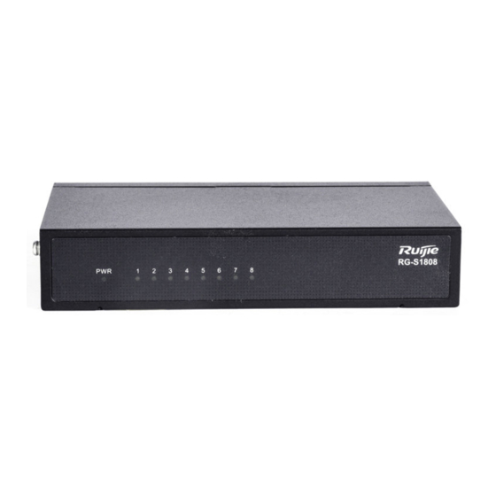
Capacity(Gbps) Product Appearance The front panel of RG-S1808 Ethernet switch provides a Power Status LED indicator and Link/ACT Status LED indicators. The rear panel provides eight 10/100BASE-T Ethernet ports and one DC power input port. Figure 1-1 shows appearance of the RG-S1808. - Page 8 Hardware Installation and Reference Guide Product Overview Front Panel Figure 1-2 Front Panel of RG-S1808 Note Power status indicator 10/100BASE-T Link/ACT indicator Rear Panel Figure1-3 Rear Panel of RG-S1808 Note 10/100BASE-T ports DC power input port Power Supply RG-S1808 switch can be powered with DC power.
-
Page 9: Rg-S1826
Hardware Installation and Reference Guide Product Overview RG-S1808 switch is designed with no fans. To ensure good dissipation, sufficient space (10 cm distance from both sides and the back panel of the chassis) should be reserved for ventilation. Dust the device every three months to avoid blocking the ventilation openings. - Page 10 Hardware Installation and Reference Guide Product Overview Power Consumption 12W(Max) Operating 0º C to 50º C (32º F to 122º F) Temperature Storage Temperature -40º C to +70º C (-40º F to 158º F) 10% to 90% RH non-condensing Operating Humidity Storage Humidity 5% to 90% RH non-condensing EN55032(Class A)
-
Page 11: Rg-S1800G Series Switch
Hardware Installation and Reference Guide Product Overview Note Grounding connector 2. AC power input port Power Supply The RG-S1826 switch can be powered with AC power. Rated voltage range: 100V to 240V Max voltage range: 90V to 290V Frequency: 50/60Hz Rated current: 0.5A Power Cord Requirements: 10A Heat Dissipation... - Page 12 Hardware Installation and Reference Guide Product Overview Ports 8-port 10/100/1000 BASE-T AC input: Power Supply Rated voltage range: 100V to 240V Max voltage range: 90V to 290V Frequency: 50/60Hz Rated current: 0.3A Not supported Power Consumption 2.5W(Max) Operating Temperature 0º C to 50º C (32º F to 122º F) Storage Temperature -40º...
- Page 13 Hardware Installation and Reference Guide Product Overview Note 1. Power status indicator 3. Power cord retention clip 2. 10/100/1000BASE-T Link/ACT/Speed indicator Rear Panel Figure1-9 Rear Panel of RG-S1808G Note Grounding connector AC power input port Power Supply The RG-S1808G switch can be powered with AC power.
-
Page 14: Rg-S1818G
Hardware Installation and Reference Guide Product Overview The port is receiving or transmitting Blinking orange traffic at 10/100 Mbps. Solid green The port is connected at 1000 Mbps. The port is receiving or transmitting Blinking green traffic at 1000 Mbps. 1.2.2 RG-S1818G Technical Specifications Model... - Page 15 Hardware Installation and Reference Guide Product Overview Switching 36Gbps Capacity(Gbps) Product Appearance The front panel of RG-S1818G Ethernet switch provides 16 10/100/1000BASE-T Ethernet ports, two 1000BASE-X SFP ports. The rear panel provides an AC power input port and a grounding connector. Figure 1-10 Appearance of RG-S1818G Front Panel Figure 1-11...
-
Page 16: Rg-S1826G
Hardware Installation and Reference Guide Product Overview RG-S1818G switch can be powered with AC power. Rated voltage range: 100V to 240V voltage range: 90V to 290V Frequency: 50/60Hz Rated current: 0.5A Power cord requirement: 10A Heat Dissipation The RG-S1818G switch is designed with no fans. To ensure good dissipation, sufficient space (10 cm distance from both sides and the back panel of the chassis) should be reserved for ventilation. - Page 17 Hardware Installation and Reference Guide Product Overview Mini-GBIC-ZX80 Mini-GBIC-ZX100 1000Base-T: Mini-GBIC-GT The supported module type may change at any time. Consult us for the detailed change information. SFP Ports Support 1000Base-X AC input: Rated voltage range: 100V to 240V Power Supply Max voltage range: 90V to 290V Frequency: 50/60Hz Rated current: 0.5A...
- Page 18 Hardware Installation and Reference Guide Product Overview Note 1. Power status indicator 5.1000BASE-X SFP port 10/100/1000BASE-T Link/ACT/Speed indicator 1000BASE-T SFP port indicator 10/100/1000BASE-T Ethernet port Rear Panel Figure1-15 Rear Panel of RG-S1826G Note 1. Grounding connector 2. AC power input port Power Supply RG-S1826G switch can be powered with AC power: Rated voltage...
-
Page 19: Module
Hardware Installation and Reference Guide Product Overview Solid orange The port is connected at 10/100 Mbps. The port is receiving or transmitting traffic Blinking orange at 10/100 Mbps. Solid green The port is connected at 1000 Mbps. The port is receiving or transmitting traffic Blinking green at 1000 Mbps. - Page 20 Hardware Installation and Reference Guide Product Overview Product Appearance The front panel of RG-S1809-P Ethernet switch provides a power LED indicator, PoE LED indicators and Link/ACT LED indicators, 8-port 10/100BASE-T Ethernet ports and one Gigabit uplink port. Figure 1-16 Appearance of RG-S1809-P Front Panel Figure 1-17 Front Panel of RG-S1809-P Note...
-
Page 21: Rg-S1800G-P Series Switch
Hardware Installation and Reference Guide Product Overview Rated current: 2.3A Rated voltage: 53.5V Heat Dissipation RG-S1809-P switch is designed with no fans. To ensure good dissipation, sufficient space (10 cm distance from both sides and the back panel of the chassis) should be reserved for ventilation. Dust the device every three months to avoid blocking the ventilation openings. - Page 22 Hardware Installation and Reference Guide Product Overview Model RG-S1826G-P 24-port 10/100/1000BASE-T Ports 2-port 1000BASE-X SFP SFP Type Ethernet Gigabit: Mini-GBIC-SX Mini-GBIC-LX Mini-GBIC-LH40 Mini-GBIC-ZX50 Mini-GBIC-ZX80 Mini-GBIC-ZX100 1000BASE-T: Mini-GBIC-GT The supported module type may change at any time. Consult us for the detailed change information.
- Page 23 Hardware Installation and Reference Guide Product Overview Front Panel Figure 1-23 Front Panel of RG-S1826G-P Note 1. Power status indicator 5.10/100/1000 BASE-T port 2.10/100/1000 BASE-T 6.1000BASE-X SFP port Link/ACT/Speed indicator 3.PoE Status indicator 4.1000BASE-X SFP port indicator Rear Panel Figure1-24 Rear Panel of RG-S1826G-P Note Grounding connector AC power input port...
-
Page 24: Module
Hardware Installation and Reference Guide Product Overview The switch adopts turbine fans for heat dissipation, thereby ensuring normal function of the device in the specified environment. 10 cm distance space should be reserved at both sides and the back plane of the cabinet to allow air circulation. -
Page 25: Preparation Before Installation
Hardware Installation and Reference Guide Preparation before Installation 2 Preparation before Installation 2.1 Safety Suggestions To avoid personal injury and equipment damage, please carefully read the safety suggestions before you install the switch. The following safety suggestions do not cover all possible dangers. 2.1.1 Safety Precautions for Installing the System ... -
Page 26: Static Discharge Damage Prevention
Hardware Installation and Reference Guide Preparation before Installation 2.1.4 Static Discharge Damage Prevention To prevent damage from static electricity, pay attention to the following: Proper grounding of grounding screws on the back panel of the device. Use of a three-wire single-phase socket with protective earth wire (PE) as the AC power socket. -
Page 27: Cleanness Requirements
Hardware Installation and Reference Guide Preparation before Installation Table 2-1 Temperature and Humidity Requirements Temperature Relative Humidity 0º C to 50º C (32º F to 122º F) 10% to 90% RH The requirements for the sampling site of the temperature and humidity in the operating environment of the device are as follows: There is no protective plate at the front or back of the equipment rack. -
Page 28: System Grounding Requirements
Hardware Installation and Reference Guide Preparation before Installation (including grounding systems), and wires (power cables, signal cables and outgoing transmission cables). For that purpose, note that: For the AC power supply system TN, single-phase three-core power socket with protective earthing conductors (PE) should be adopted to effectively filter out interference from the power grid through the filtering circuit. -
Page 29: Lightning Resistance Considerations
Hardware Installation and Reference Guide Preparation before Installation should be less than 1 ohm. The switch backplane is reserved with one grounding pole, as shown in Figure 2-1, Figure 2-2, and Figure 2-3. Figure 2-1 Figure 2-2 Figure 2-3 2.2.6 Lightning Resistance Considerations When the AC power cable is imported outdoors and directly connected to the power port of the switch, lightning line bank should be adopted to prevent the switch from being hit by lightning shocks. -
Page 30: Emi Consideration
Hardware Installation and Reference Guide Preparation before Installation The lightning line banks are not provided and should be purchased by users as required. For the usage of lightning line banks, refer to their related manuals. 2.2.7 EMI Consideration Electro-Magnetic Interference (EMI), from either outside or inside the equipment or application system, affects the system in the conductive ways such as capacitive coupling, inductive coupling, and electromagnetic radiation. -
Page 31: Product Installation
Hardware Installation and Reference Guide Product Installation 3 Product Installation Please ensure that you have carefully read the section of “Preparation before Installation”. Make sure that the requirements set forth in section of “Preparation before Installation” have been met. 3.1 Installation Procedure 3.2 Confirmations before Installation Before installation, please confirm the following points: ... -
Page 32: Installing The Rg-S1800 Series
The RG-S1800 series switches are designed with the EIA standard dimensions. RG-S1826 can be installed in 19-inch rack, while RG-S1808 does not support rack mounting. Step 1: Take out supplied screws and brackets, and then mount the brackets onto left and right sides of the switch. -
Page 33: Mounting The Switch On The Wall
3.4.2 Mounting the Switch on the Wall The RG-S1800 series switches can be mounted on a wall (RG-S1808 does not support wall mounting). Step 1: Take out supplied screws and brackets. And then rotate the brackets by 90° when it is mounted on the wall. -
Page 34: Mounting The Switch To A Workbench
Hardware Installation and Reference Guide Product Installation 3.4.3 Mounting the Switch to a Workbench In some cases, users do not have the 19-inch standard cabinet. The common solution is to place the switch on a clean workbench. The operation is simple as follows: Step 1: Attach the four rubber pads to the four corners on the switch bottom. -
Page 35: Mounting The Switch On The Wall
Hardware Installation and Reference Guide Product Installation Step 2: Place the switch into the rack. Fix the other ends of both brakcets onto the suqre hole strips of the rack by using screws and cage nuts, as shown in Figure 3-8. Figure 3-8 Fixing the Brackets to the Rack 3.5.2 Mounting the Switch on the Wall The RG-S1800G series switches can be mounted on a wall. -
Page 36: Mounting The Switch To A Workbench
Hardware Installation and Reference Guide Product Installation Step 2: Fix the switch onto the wall by using expansion screws. 3.5.3 Mounting the Switch to a Workbench In some cases, users do not have the 19-inch standard cabinet. The common solution is to place the switch on a clean workbench. -
Page 37: Installing The Rg-S1800-P Series
Hardware Installation and Reference Guide Product Installation Figure 3-11 Placing the Switch on the Workbench 3.6 Installing the RG-S1800-P Series 3.6.1 Mounting the Switch to a Workbench In some cases, users do not have the 19-inch standard cabinet. The common solution is to place the switch on a clean workbench. -
Page 38: Mounting The Switch On The Wall
Hardware Installation and Reference Guide Product Installation 3.6.2 Mounting the Switch on the Wall The RG-S1809-P series switches can be mounted on a wall. Step1: Drill two holes on the wall. Tap wall anchors into the holes. Figure 3-14 Step 2: Drive screws into the anchors. Figure 3-15 Step 3: Mount the switch to wall through the screws. - Page 39 Hardware Installation and Reference Guide Product Installation Step 4: Complete installation. Figure 3-17...
-
Page 40: Installing The Rg-S1800G-P Series
Hardware Installation and Reference Guide Product Installation 3.7 Installing the RG-S1800G-P Series 3.7.1 Mounting the Switch in the Rack The RG-S1800G-P series switches are designed with the EIA standard dimensions. RG-S1826G-P can be installed in 19-inch rack. Step 1: Take out supplied screws and brackets, and then mount the brackets onto left and right sides of the switch. Figure 3-18 Attaching the Mounting Brackets to the Switch Step 2: Place the switch into the rack. -
Page 41: Mounting The Switch To A Workbench
Hardware Installation and Reference Guide Product Installation Step 2: Fix the switch onto the wall by using expansion screws. 3.7.3 Mounting the Switch to a Workbench In some cases, users do not have the 19-inch standard cabinet. The common solution is to place the switch on a clean workbench. -
Page 42: Connecting The Power Cord
Hardware Installation and Reference Guide Product Installation 3.8 Connecting the Power Cord Make sure the socket is powered off and the switch is properly grounded before the power cord is connected. Connect the AC power cord Insert the AC power plug into the device. Take out the anti-loose buckle. -
Page 43: Checking After Installation
Hardware Installation and Reference Guide Product Installation 3.9 Checking after Installation Before checking the installation, switch off the power supply so as to avoid any personal injury or damage to the component due to connection errors. Check that the ground line is connected. ... -
Page 44: Maintenance And Troubleshooting
Hardware Installation and Reference Guide Maintenance and Troubleshooting 4 Maintenance and Troubleshooting 4.1 General Troubleshooting Procedure 4.2 Common Faults Symptom Possible Causes Solution The PWR indicator is The power supply module does not Check whether the power socket at the equipment not on after the switch supply power. - Page 45 Hardware Installation and Reference Guide Maintenance and Troubleshooting Symptom Possible Causes Solution The interconnected optical module type matched type. does not match. Replace the optical fiber with one of the The fiber type is not correct. appropriate type. The length of the optical fiber exceeds Replace the optical fiber with one of the that rated of the optical module.
-
Page 46: Appendix A: Connectors And Connection Media
Hardware Installation and Reference Guide Appendix A: Connectors and Connection Media Appendix A: Connectors and Connection Media 1000BASE-T/100BASE-TX/10BASE-T Ports The 1000BASE-T/100BASE-TX/10BASE-T is a port that supports adaptation of three rates, and automatic MDI/MDIX Crossover at these three rates. The 1000BASE-T complies with IEEE 802.3ab, and uses the cable of 100-ohm Category-5 or Supper Category-5 UTP or STP, which can be up to 100 m. - Page 47 Hardware Installation and Reference Guide Appendix A: Connectors and Connection Media Optical Fiber Connection For the optical fiber ports, select single-mode or multiple-mode optical fibers for connection according to the fiber module connected. The connection schematic diagram is shown in Figure A-4: Figure A-4 Optical Fiber Connections...
-
Page 48: Appendix B Mini-Gbic Modules
Hardware Installation and Reference Guide Appendix B Mini-GBIC Modules Appendix B Mini-GBIC Modules We provide appropriate SFP modules (Mini-GBIC) modules according to the types of interfaces of the switch modules. You can select the module to suit your specific needs. The 100M/1000M SFP module supports the following modules as well as the 100M/1000M fiber/copper conversion SFP module (Mini-GBIC-GT). - Page 49 Hardware Installation and Reference Guide Appendix B Mini-GBIC Modules MINI-GBIC-ZX100-SM1 Single-mode 1,550 9/125 100km fiber For the optical module with transmission distance exceeding 40 km and more, one on-line optical attenuator should be added on the link to avoid the overload of the optical receiver when short single-mode optical fibers are used.
Need help?
Do you have a question about the RG-S1808 and is the answer not in the manual?
Questions and answers