
Related Manuals for Ruijie RG-SF2920 Series


Summary of Contents for Ruijie RG-SF2920 Series
- Page 1 Ruijie RG-SF2920 Series Switches Hardware Installation and Reference Guide Document Version: V1.2 Date: 2022.03.30 Copyright © 2022 Ruijie Networks...
- Page 2 All rights are reserved in this document and this statement. Any reproduction, excerption, backup, modification, transmission, translation or commercial use of this document or any portion of this document, in any form or by any means, without the prior written consent of Ruijie Networks is prohibited.
- Page 3 Preface Intended Audience This document is intended for: Network engineers Technical support and servicing engineers Network administrators Technical Support Ruijie Networks Website: https://www.ruijienetworks.com/ Technical Support Website: https://ruijienetworks.com/support Case Portal: https://caseportal.ruijienetworks.com Community: https://community.ruijienetworks.com ...
- Page 4 Warning An alert that calls attention to important rules and information that if not understood or followed can result in data loss or equipment damage. Caution An alert that calls attention to essential information that if not understood or followed can result in function failure or performance degradation.
-
Page 5: Product Introduction
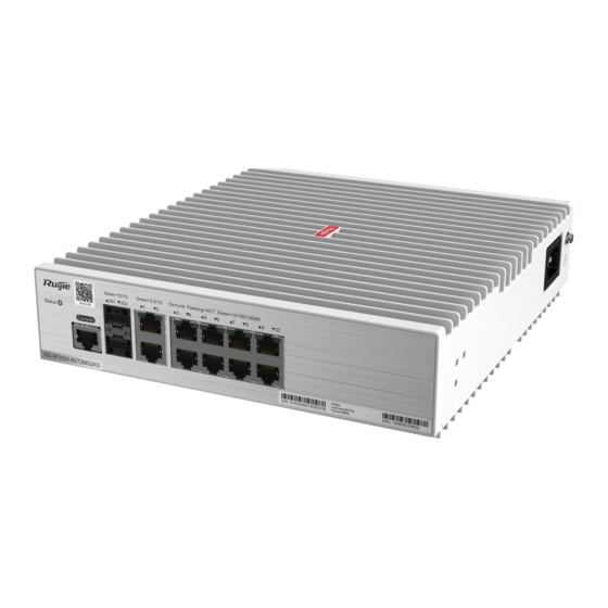
They are equipped with built-in power supplies, metal housings, and network ports, ensuring reliability and stability. They are suitable for indoor scenarios. With Ruijie's modular OS, the RG-SF2920 series switches support the simplistic optical Ethernet solution, and implement lifecycle management, security control, plug and play, and intelligent O&M through software-defined networking (SDN). - Page 6 256 MB SDRAM DDRIII 512 MB Supported Optical For details, see Appendix B. Module Type The module types may update without prior notification. Please contact Ruijie Networks for details. SFP+ Port 10GBase-R and 1000Base-X supported Power Supply AC input: Rated voltage: 200–240 V~...
- Page 7 Hardware Installation and Reference Guide Product Introduction Front Panel Figure 1-2 Front Panel of RG-SF2920-8GT2MG2XS Remarks 1. System status indicator 5. 1G/2.5GBase-T adaptive Ethernet port indicator 2. Console port 6. 1G/2.5GBase-T adaptive Ethernet port 3. Optical port indicator 10/100/1000Base-T adaptive Ethernet port 4.
- Page 8 Built-in CPU, single-core processor, clock speed of 1 GHz BOOTROM Flash Memory 256 MB SDRAM DDRIII 512 MB Supported Optical For details, see Appendix B. Module Type The module types may update without prior notification. Please contact Ruijie Networks for details. SFP+ Port 10GBase-R and 1000Base-X supported...
- Page 9 Hardware Installation and Reference Guide Product Introduction Power Supply AC input: Rated voltage: 200–240 V~ Rated frequency: 50/60 Hz Rated current: 3 A Leakage Current to ≤3.5 mA Ground EEE Function Supported PoE Function Ethernet electrical ports 1–8 support PoE and Ethernet electrical ports 9–10 do not support PoE.
- Page 10 Hardware Installation and Reference Guide Product Introduction Front Panel Figure 1-5 Front Panel of RG-SF2920-8GT2MG2XS-P Remarks 1. System status indicator 6. SFP/SFP+ port 2. PoE indicator 7. 1G/2.5G/5GBase-T adaptive Ethernet port indicator 3. Mode button 8. 1G/2.5G/5GBase-T adaptive Ethernet port 4.
- Page 11 256 MB SDRAM DDRIII 512 MB Supported Optical Only 1000Base-X is supported. For details, see Appendix B. Module Type The module types may update without prior notification. Please contact Ruijie Networks for details. SFP Port 1000Base-X supported Power Supply ...
- Page 12 Hardware Installation and Reference Guide Product Introduction –40° C to 70° C Storage Temperature Operating Humidity 10% to 90% RH Storage Humidity 5% to 95% RH Fanless design, natural heat dissipation Intelligent The temperature alarm and overheat protection functions are supported. Temperature Control GB/T 9254-2008 Safety Regulation...
- Page 13 Hardware Installation and Reference Guide Product Introduction Remarks 1. System status indicator 4. SFP port 2. Console port 5. 10/100/1000Base-T adaptive Ethernet port indicator 3. Optical port indicator 6. 10/100/1000Base-T adaptive Ethernet port Side Panel Figure 1-9 Side Panel of RG-SF2920-16GT2SFP Remarks 1.
- Page 14 256 MB SDRAM DDRIII 512 MB Supported Optical Only 1000Base-X is supported. For details, see Appendix B. Module Type The module types may update without prior notification. Please contact Ruijie Networks for details. SFP Port 1000Base-X supported Power Supply ...
- Page 15 Hardware Installation and Reference Guide Product Introduction Front Panel Figure 1-11 Front Panel of RG-SF2920-16GT2SFP-P Remarks 1. System status indicator 5. Optical port indicator 2. PoE indicator 6. SFP port 3. Mode button 7. 10/100/1000Base-T adaptive Ethernet port indicator 4. Console port 8.
- Page 16 Hardware Installation and Reference Guide Product Introduction Remarks 1. Grounding connector 2. Power port Power Supply RG-SF2920-16GT2SFP-P adopts an AC power supply, with the rated values as follows: Rated voltage: 200–240 V~ Rated frequency: 50/60 Hz Rated current: 3 A ...
- Page 17 256 MB SDRAM DDRIII 512 MB Supported Optical For details, see Appendix B. Module Type The module types may update without prior notification. Please contact Ruijie Networks for details. SFP+ Port 10GBase-R and 1000Base-X supported Power Supply AC input: Rated voltage: 200–240 V~...
- Page 18 Hardware Installation and Reference Guide Product Introduction Front Panel Figure 1-14 Front Panel of RG-SF2920-16GT2MG2XS Remarks 1. System status indicator 5. 1G/2.5GBase-T adaptive Ethernet port indicator 2. Console port 6. 1G/2.5GBase-T adaptive Ethernet port 3. Optical port indicator 7. 10/100/1000Base-T adaptive Ethernet port indicator 4.
- Page 19 Hardware Installation and Reference Guide Product Introduction Remarks 1. Grounding connector 2. Power port Power Supply RG-SF2920-16GT2MG2XS adopts an AC power supply, with the rated values as follows: Rated voltage: 200–240 V~ Rated frequency: 50/60 Hz Rated current: 0.6 A ...
- Page 20 256 MB SDRAM DDRIII 512 MB Supported Optical For details, see Appendix B. Module Type The module types may update without prior notification. Please contact Ruijie Networks for details. SFP+ Port 10GBase-R and 1000Base-X supported Power Supply AC input: Rated voltage: 200–240 V~...
- Page 21 Hardware Installation and Reference Guide Product Introduction Front Panel Figure 1-17 Front Panel of RG-SF2920-16GT2MG2XS-P Remarks 1. System status indicator 6. SFP/SFP+ port 2. PoE indicator 7. 1G/2.5G/5GBase-T adaptive Ethernet port indicator 3. Mode button 8. 1G/2.5G/5GBase-T adaptive Ethernet port 4.
- Page 22 Hardware Installation and Reference Guide Product Introduction Remarks 1. Grounding connector 2. Power port Power Supply RG-SF2920-16GT2MG2XS-P adopts an AC power supply, with the rated values as follows: Rated voltage: 200–240 V~ Rated frequency: 50/60 Hz Rated current: 0.6 A ...
- Page 23 Hardware Installation and Reference Guide Product Introduction Blinking The port is sending or receiving data at green 10G/1G. An error occurs when the optical module Solid red sends signals. An error occurs when the optical module Solid yellow receives signals.
-
Page 24: Preparations Before Installation
Hardware Installation and Reference Guide Preparations Before Installation 2 Preparations Before Installation 2.1 Safety Precautions To avoid personal injury and device damage, carefully read the safety precautions before you install the RG-SF2920 series switches. The following safety precautions may not cover all possible dangers. 2.1.1 Installation Safety Keep the chassis clean, free from any dust. - Page 25 2.1.5 Laser Safety The RG-SF2920 series switches support various types of optical modules available in the market, and these optical modules are Class I laser products. Improper use of an optical module may cause damage. Therefore, pay attention to the...
- Page 26 2.2.1 Ventilation and Cooling Requirements For RG-SF2920 series switches, maintain sufficient space on both sides of the chassis and around the back panel for air circulation and ventilation. After various cables are connected, bind the cables or place them in the cable management bracket to avoid blocking air inlets.
- Page 27 2.2.5 Grounding Requirements A proper grounding system is the basis for stable and reliable running of the RG-SF2920 series switches and is indispensable for preventing lightning strikes and interference. Carefully check the grounding conditions at the installation site according to the grounding specifications, and complete grounding properly based on the actual situation.
- Page 28 The resistance of the ground cable should be smaller than 1 ohm, Each of the RG-SF2920 series switches provides one grounding connector on the side panel, as shown in Figure 2-1.
- Page 29 Tools and meters Phillips screwdriver, slotted screwdriver, related copper and optical cables, bolts, Common Tools diagonal pliers, cable ties ESD tools Special Tools Multimeter Meters The RG-SF2920 series switches are delivered without a tool kit. Customers need to get ready the tools.
-
Page 30: Product Installation
The installation environment meets the temperature and humidity requirements. The power supply and required current are available in the installation site. The network cables have been deployed in the installation site. 3.3 Installing RG-SF2920 Series Switches Precautions Pay attention to the following points during installation:... - Page 31 Lay out the 100-meter network cable only indoors. Take lightning protection measures if it needs to be routed outdoors. 3.3.1 Installing the Switch in a Rack The RG-SF2920 series switches meet the EIA standard size and can be installed in racks. Maintain sufficient space around the devices for heat dissipation. The installation requirements are as follows: 1.
- Page 32 Hardware Installation and Reference Guide Product Installation Installed in a 19-inch rack Left Right Step 2: As shown in Figure 3-2, horizontally mount the device to an appropriate position inside the rack and use M6 screws and cage nuts to secure the other end of the mounting brackets to square hole posts of the rack. The switch after installation is shown in Figure 3-3.
- Page 33 Product Installation 3.3.2 Mounting the Switch at the Bottom of a Table The RG-SF2920 series switches can be directly installed at the bottom of a table. Maintain sufficient space around the device for heat dissipation. The installation requirements are as follows: The bottom of the table must be well-ventilated.
- Page 34 Note: When the device is mounted on a wall, it is only suitable to be mounted on a concrete or non-flammable surface. 3.3.4 Installing the Switch in a Weak-Current Box The RG-SF2920 series switches can be installed in a weak-current box. The installation requirements are as follows:...
- Page 35 Hardware Installation and Reference Guide Product Installation The ambient temperature around the weak-current box needs to be lower than or equal to 40° C. The requirements for the weak-current box size and opening area proportion are as follows: Model Minimum Size of Weak-Current Opening Area Proportion on the Panel RG-SF2920-8GT2MG2XS ≥...
- Page 36 Hardware Installation and Reference Guide Product Installation When the device needs to be installed in a weak-current box, the size of the weak-current box should be greater than 400 mm × 300 mm × 120 mm, with the opening rate greater than 15%. It is forbidden to stack multiple devices in the weak-current box.
- Page 37 Hardware Installation and Reference Guide Product Installation ③ Connect the power cord to the device, confirm the power supply, close the door of the weak-current box, and lock it with the key. Method 2 of installing a switch on the bracket in the weak-current box: ①...
- Page 38 Hardware Installation and Reference Guide Product Installation ③ Connect the power cord to the device, confirm the power supply, close the door of the weak-current box, and lock it with the key.
- Page 39 Hardware Installation and Reference Guide Product Installation 3.4 Check After Installation Turn off the power to avoid personal injury and damage to components caused by incorrect connection. Verify that the ground cable is connected. Verify that the cables and power input cables are correctly connected. Verify that the 100-meter network cable is routed indoors.
-
Page 40: System Debugging
Hardware Installation and Reference Guide System Debugging 4 System Debugging 4.1 Setting Up the Debugging Environment Setting Up the Debugging Environment Connect a PC to the console port of the switch by using an Ethernet cable, as shown in Figure 4-1. Figure 4-1 Setting Up the Environment Connected to the console port of the switch... - Page 41 Hardware Installation and Reference Guide System Debugging In the Name box, enter the new connection name and click OK. The Connect to dialog will appear, as shown in Figure 4-3. From the Connect using drop-down list, select a COM port to be used. Figure 4-3 Click OK.
- Page 42 Hardware Installation and Reference Guide System Debugging Click OK and HyperTerminal window will appear. 4.2 Checking the Device Startup Check Before Device Power-On Check that the switch is fully grounded. Check that the power cord is properly connected. ...
-
Page 43: Common Troubleshooting Procedures
5.2 Common Troubleshooting Procedures Symptom Possible Cause Solution You forget the login You forget the password after manually Contact Ruijie Networks Customer Service password. configuring it. Department for technical support. The status indicator is off Check whether the power socket in the... - Page 44 Hardware Installation and Reference Guide Common Troubleshooting in Installation Change the serial port enabled on the The serial port connected to the switch is configuration software to the serial port The serial port console different from that enabled on the connected to the switch.
-
Page 45: Appendix A - Connectors And Media
Appendix A — Connectors and Media Hardware Installation and Reference Guide Appendix A — Connectors and Media 1000BASE-T/100BASE-TX/10BASE-T Port 1000BASE-T/100BASE-TX/10BASE-T is a 10/100/1000M auto-negotiation port that supports auto MDI/MDIX Crossover. Compliant with IEEE 802.3ab, 1000BASE-T requires Category 5 or Category 5e 100-ohm UTP or STP (STP is recommended) with a maximum distance of 100 meters. - Page 46 Appendix A — Connectors and Media Hardware Installation and Reference Guide Straight-through cable Optical Fiber Connection Choose SMF or MMF optical fibers according to the optical module types. Figure A-4 shows the connection. Figure A-4 Optical Fiber Connection Switch Switch - 42 -...
-
Page 47: Appendix B - Mini-Gbic And Sfp+ Modules
Appendix B — Mini-GBIC and SFP+ Modules Ruijie provide supporting SFP modules (mini-GBIC modules) and 10G SFP+ modules based on the port types of switch modules. You can select a module to suit your specific needs. This document provides models and technical specifications of some 1000M SFP modules and 10G SFP+ modules for reference. - Page 48 Appendix B — Mini-GBIC and SFP+ Modules Hardware Installation and Reference Guide GE-SFP-LX20-SM1550-BIDI Single-mode 9/125 20 km SDH155-SFP-SX-MM850 Multi-mode 62.5/125 500 m SDH155-SFP-SX-MM1310 Multi-mode 62.5/125 2 km SDH155-SFP-LH15-SM1310 Single-mode 9/125 15 km 62.5/125 275 m GE-SFP-SX Multi-mode 50/125 550 m GE-SFP-LX Single-mode 9/125...
- Page 49 Appendix B — Mini-GBIC and SFP+ Modules Hardware Installation and Reference Guide 500(OM2) 82 m 400(OM1) 66 m XS-SFP-LR Single-mode 9/125 10 km An optical module is a laser transmitter. Do not stare at any light source to prevent it from burning your eyes. To keep the module clean, make sure that the dust cap is mounted when it is not connected to cables.
-
Page 50: Appendix C - Lightning Protection
Appendix C — Lightning Protection Hardware Installation and Reference Guide Appendix C — Lightning Protection Installing an AC Power Arrester (Lightning Resistance Socket) When an AC power cord is introduced from outdoors and directly connected to the power port of the switch, the AC power port must be connected to an external lightning resistance socket to protect the switch against lightning strokes. - Page 51 Appendix C — Lightning Protection Hardware Installation and Reference Guide Connect an Ethernet port arrester to the switch to prevent the damage by lightning before connecting an outdoor network cable to the switch. Tools: Phillips screwdrivers or flat-head screwdriver, multimeter, and diagonal pliers Installation steps: Tear one side of the protective paper for the double-sided adhesive tape and paste the tape to the housing of the Ethernet port arrester.
-
Page 52: Appendix D - Cabling Recommendations
Appendix D — Cabling Recommendations Hardware Installation and Reference Guide Appendix D — Cabling Recommendations When the switch is installed in a standard 19-inch cabinet, secure the cables around the cable management brackets. Adopt top cabling or bottom cabling according to the actual situation in the equipment room. All cable connectors used for transit should be placed at the bottom of the cabinet rather than be exposed outside of the cabinet. - Page 53 Appendix D — Cabling Recommendations Hardware Installation and Reference Guide Tangled Bent Route and bind power, signal, ground cables separately. When the cables are close to each other, cross them. Mixed binding is not allowed. When they are close to each other, it is recommended to adopt crossover cabling. In the case of parallel cabling, maintain a minimum distance of 30 mm between power cords and signal cables.
- Page 54 Appendix D — Cabling Recommendations Hardware Installation and Reference Guide When cables need to be bent, bind them first before bending them. However, cable ties cannot be attached within the bend area. Otherwise, considerable stress may be generated on cables, breaking cable cores, as shown in Figure D-3.
- Page 55 Appendix D — Cabling Recommendations Hardware Installation and Reference Guide Flat washer Nut Flat Spring washer washer When using a stiff cable, fix it near the cable lug to avoid stress on the lug and cable. Do not use self-tapping screws to fasten terminal blocks. ...
-
Page 56: Appendix E - Equipment Room Site Selection
Appendix E — Equipment Room Site Selection Hardware Installation and Reference Guide Appendix E — Equipment Room Site Selection The equipment room should be at least 5 km away from heavy pollution sources, such as the smelter works, coal mine, and thermal power plant.
Need help?
Do you have a question about the RG-SF2920 Series and is the answer not in the manual?
Questions and answers