Table of Contents
Advertisement
Quick Links
Advertisement
Table of Contents

Related Manuals for Thermo Scientific Multiskan FC


Summary of Contents for Thermo Scientific Multiskan FC
- Page 1 Thermo Scientific Multiskan FC User Manual Rev. 2.2, Cat. No. N07710...
- Page 2 Warranty The Thermo Scientific Microplate Instrumentation products are fully guaranteed against defective parts and materials, including defects caused by poor workmanship for a period of one year from the date of delivery.
- Page 3 Perform basic cleaning and maintenance procedures Troubleshoot the instrument performance This user manual also describes all the features and specifications of the Multiskan FC instrument as well as ordering information. Read the manual in its entirety before operating the instrument.
- Page 4 These symbols are intended to draw your attention to particularly important information and alert you to the presence of hazards as indicated. Safety symbols and markings used on the Multiskan FC The following symbols and markings appear on the type label and the instrument itself.
- Page 5 Warning and other markings used in the documentation The following symbols and markings appear in this user manual. Warning! Risk of electric shock. Warning! Biohazard risk. Warning! Hot plate, risk of burns. Risk of injury to the user(s). Caution! Risk of damage to the instrument, other equipment or loss of performance or function in a specific application.
-
Page 6: Table Of Contents
Table of Contents Chapter 1: Introduction to the Multiskan FC ................... 9 Intended use ............................ 9 Principle of operation ........................9 Chapter 2: Installation ........................10 Unpacking ............................10 How to unpack ..........................10 Checking delivery for completeness or damage ................11 Environmental requirements...................... - Page 7 Results in list format ........................42 Settings menu ..........................43 Chapter 6: Starting Ready-made Protocols .................. 44 Starting a ready-made protocol with the quick keys (F1-F3) ............44 Starting a ready-made protocol from the list ................... 45 Chapter 7: Protocol Creation Examples ..................47 Opening a new protocol .........................
- Page 8 Chapter 16: Ordering Information ....................83 List of filters ............................ 83 List of spare parts and accessories ....................83 List of Thermo Scientific plates ...................... 84 Verification tools ..........................84 Appendix A: System Log ........................ 85 Appendix B: Certificate of Decontamination ................86...
-
Page 9: Chapter 1: Introduction To The Multiskan Fc
The Multiskan FC, as standalone instrument or with SkanIt Software, can be used in research or routine-test laboratories by professional personnel. The Multiskan FC is part of the analyzing system used by the end user, who therefore is responsible for validation of the whole system for reliable and safe results. -
Page 10: Chapter 2: Installation
Chapter 2: Installation The Multiskan FC weighs 8.5 kg [18.7 lbs.] and care must be taken when lifting it. Unpacking How to unpack Move the packed instrument to its site of operation. -
Page 11: Checking Delivery For Completeness Or Damage
If the instrument has been mechanically damaged, ship it for service. Environmental requirements When you set up your Multiskan FC, avoid sites of operation with excess dust, vibrations, strong magnetic fields, direct sunlight, draft, excessive moisture, or large temperature fluctuations. Make sure: ... - Page 12 Figure 4. Unfastening the transport lock 3. Pull the transport lock bar out (Figure 5). Figure 5. Pulling the transport lock out 4. Keep the transport lock bar and tag (Figure 6) for future relocation or transportation of the instrument.
-
Page 13: Installing The Filter Wheel
1. Unpack the filter wheel (Figure 7). It is delivered in a filter wheel box. Check that all filters are clean and undamaged. Position slot Figure 7. Multiskan FC filter wheel Caution! Do not touch the filters with your bare hands. -
Page 14: Connecting The Power Supply Cable
Figure 9. Connecting the power supply cable Connecting to a computer If you are using a computer with the Multiskan FC, connect the communication cable to the USB port for the computer (Figure 9). Connecting to a printer If you are using a printer, connect it to the USB port for the printer (Figure 9). The external USB... -
Page 15: Switching On
Settings menu. Refer to the instructions in “Settings menu”. Installation of SkanIt Software for Microplate Readers For installing SkanIt Software for Multiskan FC, refer to the SkanIt Software for Microplate Readers User Manual (Cat. No. N16243). Caution! Operate the instrument only with software and hardware that is specifically designed or selected for it. -
Page 16: Chapter 3: Multiskan Fc Main Parts
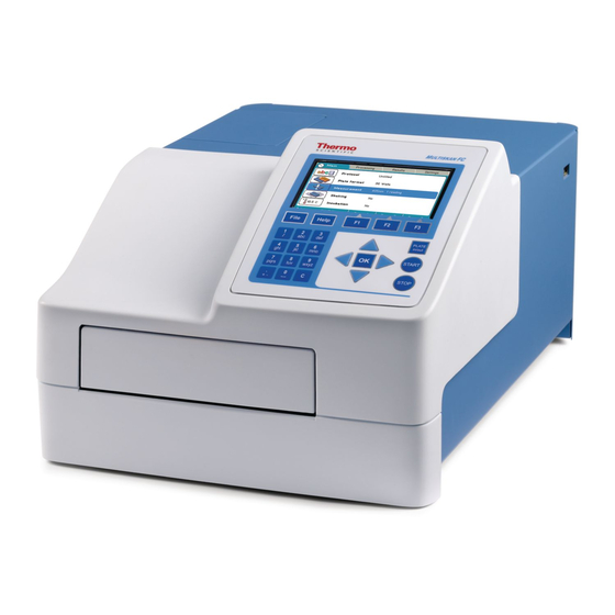
The STOP button on the keypad can be used to terminate the computer remote control. Chapter 3: Multiskan FC Main Parts Front view The front view of the Multiskan FC instrument is shown in Figure 10. Display Lamp and filter wheel... -
Page 17: Side View
Warning marking Type label Figure 11. Multiskan FC back view Side view The side view of the Multiskan FC instrument is shown in Figure 12. Lamp and filter wheel chamber cover open Plate carrier OUT Figure 12. Multiskan FC side view USB memory device port The instrument is equipped with a USB port for an external memory device (Figure 11). -
Page 18: Incubator
Chapter 15: “Troubleshooting Guide”. Incubator The optional incubator is only available with the Multiskan FC with incubator model. The incubator chamber consists of thermal elements on the top and bottom of the incubator chamber. The upper electrical thermal element prevents condensation on the microplate that is being incubated. -
Page 19: Keys / Action
Arrow keys and OK key START, STOP and PLATE in/out keys Figure 13. Keypad and display of the Multiskan FC Keys / Action The relevant keys for navigating and editing are described in detail below. The keys also have other functions depending on the level in the internal software. -
Page 20: Chapter 5: Menus And Parameters
Protocol 3 Function button Figure 14. Info text bar of the Multiskan FC user interface Press the FILE key, for example, for saving the protocol in the Main menu. Depending on the level of the internal software, the FILE key... - Page 21 The clock on the Main tab shows the real time. The Incubation icon also shows the current temperature (only Multiskan FC with incubator model). See the info text bar for the required actions of the F1-F3 keys. The action text on the info text bar changes according to the level of the internal software.
-
Page 22: Protocol
Main ↳ No ↳ 25-50 ↳ Wait for warm up ↳ Yes ↳ No ↳ Time (hh:mm:ss) ↳ 00.00.00 Depending on the level of the internal software, the FILE key opens a list of actions possible for the current protocol. Protocol The Protocol row in the Main menu shows the name of the active protocol. -
Page 23: Plate Format Parameters
Note! It is recommended to back up the protocols regularly. The backup is created by exporting the protocols to the USB memory device. Note! If you make any changes to the processing parameters of a measured run in the Processing menu, the changes are made to that run only. If you want to make changes to the protocol and thereby to the future runs, you must open the protocol, make the changes, and press the FILE key/Save to save the changes. -
Page 24: Measurement Parameters
Measurement parameters You can define the measurement filter(s), number of readings, and measurement mode in the Measurement window. Filters Filter 1 defines the first (main) filter wavelength. Filter 2 defines the second (reference) filter wavelength. You can select the suitable filter from the list of available filters. You must physically install the filter into the filter wheel, as well as introduce the additional filter to the internal software of the instrument in the Settings window. -
Page 25: Incubation Parameters
Incubation parameters Note! Incubation is only available if the instrument configuration supports incubation. You can define the incubation parameters, incubation time, and temperature in the Incubation window. The Incubation icon (and row) is visible in the Main menu of the instruments with an incubator indicating the present temperature. -
Page 26: Plate Layout Parameters
Info text bar See the info text bar for required actions. Plate layout parameters You can set the plate map of the protocol in the Plate layout window. The calculations of the results are made based on the plate layout. The plate layout parameters have to be set prior to measurement. -
Page 27: Preprocessing Parameters
Note! Blank subtraction is made automatically if the plate layout includes blanks. The blank used in the calculations is always an average of the blanks included in the layout. You can determine the sample type in Well type. The sample types are Blank, Calibrator, Control, Unknown or Empty. - Page 28 Preprocessing is used with dual (two wavelength) measurements, for example, to subtract the reference wavelength data in dual measurements and with kinetic measurements to reduce data in kinetic calculations. Table 8. Processing / Preprocessing parameters Processing / Preprocessing Preprocessing ↳...
-
Page 29: Precalculations
Processing / Preprocessing ↳Decreasing ↳ Time to change ↳ Ignore from beginning ↳0 ↳ Ignore from end ↳0 ↳ Window ↳2 ↳ Reaction ↳Undefined ↳Increasing ↳Decreasing ↳ Baseline readings ↳100 ↳ Readings from ↳Beginning ↳End ↳ Change ↳0.00 ↳ Change type ↳Absolute ↳Relative (%) ↳... -
Page 30: Kinetic Calculations
Kinetic calculations Kinetic calculations can be used when the number of readings is more than 1 in the measurement parameters (see Measurement parameters). Also the results of a kinetic calculation can be used as source data for further calculations. The available kinetic calculation types are: ... - Page 31 Figure 15. Determining the maximum rate with window value 2 You can define the following settings: Reaction – Define whether the reaction is supposed to produce increasing or decreasing signal levels. There are three options for this setting: Undefined (default) –...
- Page 32 1 to 3, the second rate using the measurements 2 to 4, and so on up to measurements 8 to 10. The maximum rate will be the maximum value among these calculated rates. Time to maximum rate The time to maximum rate is calculated similarly to the maximum rate, but the result is reported as the time in seconds from the first reading to the point on the line where the maximum rate occurs instead of the rate itself.
- Page 33 First define the base value by entering the number of readings from the start in baseline. The base value is the average of results of the given baseline count from the beginning or end of results. Then select whether the change from the base value is evaluated as a relative (%) or an absolute value and define that percentage or value.
-
Page 34: Calculation Parameters
You can define the following settings: Ignore from beginning – Ignores a defined number of points (readings), counted from the first reading. Ignore from end – Ignores a defined number of points (readings), counted from the last reading. Time to maximum The time to maximum is used to calculate the time elapsed before the maximum measurement signal in each well is reached. -
Page 35: Curve Fits
Note! Blank subtraction is made automatically if the plate layout includes blanks. The blank used in the calculations is always an average of the blanks included in the layout. Note! The plate layout must include calibrators and corresponding calibrator parameters, such as concentrations, to enable them for further calculations, for example, curve fits. -
Page 36: Factor
y = a + bx where y denotes the expected value. The minimum number of calibrators for this fit type is two. Extrapolation is only available for the linear regression fit type. The extrapolation result is merely indicative and needs to be confirmed. Results using extrapolated data are marked with “*” in list format. -
Page 37: Interpretation Parameters
Note! The stored curve must be older than the measured run data. This means that if a new curve is stored, the earlier saved assay run data cannot be recalculated against the new curve. Interpretation parameters You can define the qualitative calculation (classification) in the Interpretation window. Table 10. -
Page 38: Source Data
The absorbances or concentrations of the samples are compared to the limits and defined, for example, as negative or positive. Source data You must define the Source data for the interpretation calculation. The source data used for interpretation can include the following data types: ... -
Page 39: Quality Control Parameters
Figure 17. Interpretation and limits For instructions on how to program an interpretation to the protocol, refer to “Programming an interpretation”. Quality control parameters Quality control (QC) is used to program rules for quality control and thereby ensure that the assay works as expected. -
Page 40: Results Menu
The rules (formulas) can be entered with a QC rule editor. The editor contains the following items: Sample – Select the sample to be checked. It can be any of the calibrators or controls present in the layout or the blank. If the sample has replicates, the average value of these is automatically selected for the QC check. -
Page 41: Calculated Results
You can disable/enable samples and sample replicates from the raw data by pressing the OK button. Select Disable and press the OK button. If the user enables automatically disabled data, the user is responsible for data quality. You can print or export the selected data. For further information, refer to Chapter 8: “Viewing Results”. -
Page 42: Quality Control (Qc)
You can use both the curve on the plate and a previously created calibration curve of the same assay protocol. You can store a curve for future use with the FILE function. You can load a saved curve for the active protocol with the FILE function. If a stored curve is in use for calculation, the calibrators measured with the current plate can be taken into use with the Menu function. -
Page 43: Settings Menu
Settings menu You can set the instrument parameters in the Settings menu. The values shown in the Settings menu remain in the instrument memory and are instrument- specific, not protocol-specific. You can define System, Filters, Printer, and Startup settings. For instructions on how to modify different settings, refer to Chapter 11: “Modifying Settings”. Info text bar Table 12. -
Page 44: Chapter 6: Starting Ready-Made Protocols
Insert the assay microplate so that the A1 corner is positioned in the top left corner of the plate carrier (Figure 18). Figure 18. Multiskan FC plate carrier Warning! The plate carrier opens automatically. Make sure there is enough clearance in front of the instrument for the plate carrier to come out freely. -
Page 45: Starting A Ready-Made Protocol From The List
3. Press the START button. 4. Enter the unknown count with the number keys. 5. Press the START or OK button to accept the selection and to start the measurement. Note! If you want to cancel the run, press the F2 key. 6. - Page 46 2. Select the ready-made assay protocol you want to run from the protocol list using the Down arrow key, and then press the OK button. Note! The protocol name selected is shown on the Protocol row in the Main menu. 3.
-
Page 47: Chapter 7: Protocol Creation Examples
(wavelength, shaking, and incubation), the plate layout and precalculation, calculation and interpretation parameters, and how to save the protocol. Note! The Incubation row is only active with the Multiskan FC with incubator model. Ensure that you save the changes you make in each step. Refer to “Saving a new Note! (active) protocol”. -
Page 48: Programming Incubation
You can set the incubation time and temperature in the Incubation window. Note! The Incubation row is only active with the Multiskan FC with incubator model. Note! The temperature set in the protocol overrules the startup temperature. If the protocol does not include incubation, the startup temperature remains. -
Page 49: Programming A Plate Layout
6. Press the F1 key to accept the incubation parameters. Programming a plate layout You can start filling the plate layout on any of the wells of the plate. You start the fill procedure from the well marked with a blue square. - Page 50 3. Select the Well type item in the Add series starting from well: A1 window and press the OK button. 4. Select, for example, a Blank sample using the Up arrow key, and then press the OK button. 5. Press the F1 key to accept the selection and return to the Layout window (well A2).
- Page 51 13. Enter, for example, 1 (1.00) as the Cal 1 concentration using the number keys, and then press the OK button. 14. Select the Cal 2 item using the Down arrow key and press the OK button. 15. Enter, for example, 2 (2.00) as the Cal 2 concentration using the number keys, and then press the OK button.
-
Page 52: Programming Calculations And Interpretations
26. Select, for example, an Unknown sample using the Up arrow key, and then press the OK button. 27. Select the Number of item using the Down arrow key and press the OK button. 28. Select, for example, 91 using the number keys, and then press the OK button. -
Page 53: Programming Calculations
3. Press the F1 key to accept the precalculation. 4. Press the Left arrow key to return to the Main menu. Programming calculations 1. Select the Calculation row in the Processing menu using the Down arrow key and press the OK button. 2. - Page 54 1. Select the Interpretation row in the Processing menu using the Down arrow key and press the OK button. 2. Select Source data and press the OK button. 3. Select, for example, Raw using the Down arrow key, and then press the OK button.
-
Page 55: Adding A Qc Rule To The Protocol
10. Select Operator using the Right arrow key and press the OK button. 11. Select + and press the OK button. 12. Select Constant using the Right arrow key and press the OK button. 13. Enter the constant, for example, 0.050, using the number keys and press the OK button. -
Page 56: Saving A New (Active) Protocol
1. Select the Quality Control row in the Processing menu using the Down arrow key and press the OK button. 2. Press the OK button on the Enable quality control and select Yes using the Up arrow key, and then press the OK button. 3. -
Page 57: Chapter 8: Viewing Results
3. Enter the protocol name, for example, Test1, by using the number and letter keys, and then press the OK button. You cannot use the protocol name “Untitled”. Note! The results of an “Untitled” protocol are not saved unless you save the active protocol, Note! including the measured run data with a new name. -
Page 58: Chapter 9: Printing, Exporting Or Importing
2. Select another data view using the Up and Down arrow keys, and press the OK button. 3. Press the FILE key in the data view to print or export a data view. Select Export As Text or Print using the Down arrow key if necessary, and then press the OK button. -
Page 59: Printing Or Exporting Data
Results data is expressed as “#####” when available space is too little. Note! It is recommended to format the USB memory device if export or import fails. Printing or exporting data This section provides information on how the active run data (measurement results) can be printed or exported to the USB memory device. -
Page 60: Exporting A Protocol
(Figure 9) by using the FILE key. Runs, including protocol information and data, can be exported. Protocols can be exported and imported to another Multiskan FC instrument with the same configuration. Import of runs is only possible to the same instrument as backup. -
Page 61: Importing A Protocol
4. Press the FILE key and select Export using the Down arrow key. Then press the OK button. 5. If you also want to export the runs that are created (measured) with the protocol, press the OK button. If not, press the Right arrow key, and then the OK button. -
Page 62: Chapter 10: Shutdown
The Multiskan FC instrument’s internal software version, serial number, and model are shown in the System settings window. Model 1 refers to Multiskan FC and Model 2 to Multiskan FC with incubator. You can set the date, date and time format, and language in the System settings parameter window. -
Page 63: Filters
6. Return to the Main menu using the Right arrow key. Filters Multiskan FC comes with installed filters of 405 nm, 450 nm, and 620 nm. You can introduce a filter to the internal software by moving to the Filters settings. The filter wavelength must be between 340 and 850 nm. -
Page 64: Removing A Filter
3. Select the empty filter position by pressing the Right arrow key until the filter wheel on the display rotates to the empty position, and the text “Empty” is shown. 4. Press the OK button. Enter the wavelength of the filter, for example, 492, with the number keys, and then press the OK button. -
Page 65: Chapter 12: Emergency Situations
Note! The set startup temperature is only activated when the instrument is powered (switched on). The temperature set in the protocol overrules the startup temperature. If the protocol does not include incubation, the startup temperature remains. Chapter 12: Emergency Situations Handling emergency situations In case there is any abnormal situation during the operation, such as fluids spilling inside the instrument:... -
Page 66: General
Always ensure that the electrical supply in the laboratory conforms to that specified on the type label of the instrument. To guarantee the continuous reliability and accuracy of the Multiskan FC, avoid disturbing any of the optical system components. A misalignment of the light path affects measurements. -
Page 67: Immediate
Do not autoclave any part of this instrument. Immediate Although the Multiskan FC is constructed from high-quality materials, you must immediately wipe away spilled saline solutions, solvents, acids, or alkaline solutions from outer surfaces to prevent damage, and wipe with deionized distilled water. -
Page 68: Decontamination Procedure
Warning! The samples can be potentially infectious. Dispose of all used plates, disposable gloves, syringes, disposable tips, and so on as biohazardous waste. Be cautious and always use gloves. Decontamination procedure If you have spilled infectious agents, carry out the decontamination procedure. Decontamination should be performed in accordance with normal laboratory procedures. -
Page 69: Adding Individual Filters To The Filter Wheel
Caution! Only use filters approved by the instrument manufacturer. Caution! For certain filters you can use the Thermo Scientific™ Multiskan™ Verification Plate (Cat. No. 24072800) to verify filters added. Note! The filter is a consumable and should be changed regularly. - Page 70 Figure 20. Removing the spring position holding screws Filter spring Filter Filter wheel Next free position for additional filter Spring position holding screws Figure 21. Filter wheel parts Figure 22. Individual filter showing the arrow...
- Page 71 Note Arrow pointing up Figure 23. Inserting a filter into the next free position in the filter wheel 5. Insert a new filter or an additional optional filter (Figure 22) into the next free position in the filter wheel (Figure 23). When inserting the filter, the arrow must be pointing upwards as in Figure 23. The wavelength of the filter is marked on the filter package as well as on the filter side, that is, the three digits before the last digit of the number sequence: xxxxx NNNx, where NNN is the wavelength.
-
Page 72: Changing The Lamp
Note! The measurement results will be incorrect, if the filter parameters differ from the actual filters in the filter wheel. Now the filters are ready for use. Changing the lamp Caution! Only use the lamp approved by the supplier: Cat. No. 1410101, Lamp, quartz- halogen lamp (Osram 64222, 6V/10W). - Page 73 Match the notch of the lamp with the alignment tab! Figure 25. Clamps open Note! Place the lamp and terminal socket into the correct position. Refer to Figure 25. 8. While holding the lamp in place, turn the two clamps to lock the lamp into position (Figure 26). Figure 26.
-
Page 74: Refitting The Transport Lock
Refitting the transport lock When you relocate the instrument or ship it for service, make sure you refit the transport lock. 1. The instrument has to be powered on. 2. Press the PLATE in/out button so that the plate carrier goes in. 3. -
Page 75: Maintaining A System Log
Figure 28. Fastening the transport lock 8. Close the lamp and filter wheel chamber cover. The transport lock bar and tag are now refitted (Figure 29). Figure 29. Transport lock bar and tag refitted Maintaining a system log A system log, which includes a short summary of the use, maintenance procedures, error messages, and other information about the use of the system, is useful in properly maintaining the system. -
Page 76: How To Pack For Service
Thermo Fisher Scientific technical service department. Disposal of the instrument If the Multiskan FC is exposed to potentially infectious chemical samples, toxic or corrosive chemicals or radioactive chemicals, waste management of the complete instrument must be carried out to ensure that there is no risk of contamination. -
Page 77: Chapter 14: Technical Specifications
Chapter 14: Technical Specifications General specifications Thermo Fisher Scientific reserves the right to change any specifications without prior notice as part of our continuous product development program. Table 15. General specifications General specifications Overall dimensions ca. 290 mm (W) x 400 mm (D) x 220 mm (H) [11.4”... -
Page 78: Performance Specifications
Performance specifications Table 16. Photometry This section provides the performance specifications at typical laboratory conditions (22°C, relative humidity 40%) for the relevant measurement technique and other instrument capabilities. Performance specifications / Photometry Optical system Quartz-halogen lamp (Osram 64222, 6V/10W), interference filter (in the filter wheel), fiber, fiber end optics, photodetector, signal processing Wavelength range 340–850 nm... -
Page 79: Safety Specifications
Safety specifications This section describes the safety specifications for the Multiskan FC instrument. In conformity with the requirements Multiskan FC bears the following markings: Type 357 100–240 Vac, 50/60 Hz, 100 VA max. CE marking CSA monogram or similar The safety specifications are also met under the following environmental... - Page 80 Table 18. Error codes reported Code Explanation Suggested action The command was executed successfully. The instrument did not recognize the command Please restart both the instrument and PC. Contact it received. the PC software vendor. The arguments of the received command are Please restart both the instrument and PC.
-
Page 81: Usb Memory Device
It is not recommended to use multiple drive USB memory devices that contain virtual CD drives. The multiple drive USB memory devices normally contain one or more removable disk-type memory spaces, but can also contain virtual CD drive-type memory spaces. The Multiskan FC does not support virtual CD drive-type memory spaces. -
Page 82: Warnings And Cautions
Warnings and cautions This instrument is designed to provide full user protection. When correctly installed, operated and maintained, it will present no hazard to the user. The following recommendations are given for added user safety. Electrical Ensure that the power supply cable supplied with the unit is always used. If a correct type of mains cable is not provided, use only cables certified by the local authorities. -
Page 83: Chapter 16: Ordering Information
Chapter 16: Ordering Information Contact your local Thermo Fisher Scientific representative for ordering and service information. List of filters Table 20. Codes for filters Code Item 1423405 Optical filter 340 nm 1423755 Optical filter 375 nm 1424055 Optical filter 405 nm 1424145 Optical filter 414 nm 1424505... -
Page 84: List Of Thermo Scientific Plates
List of Thermo Scientific plates Table 22. Codes for plates Code Item 9503060 MultiFrame ™ Immulon Plates, 96 Well 3355 Flat, 1 B, Medium Binding 3455 Flat, 2 HB, High Binding 3855 Flat, 4 HBX, High Binding Extra ™ Microtiter... -
Page 85: Appendix A: System Log
Appendix A: System Log Instrument name/number: User Date Comments... -
Page 86: Appendix B: Certificate Of Decontamination
Appendix B: Certificate of Decontamination Name: Address: Tel./Fax: Instrument: Serial No.: A) I confirm that the returned items have not been contaminated by body fluids, toxic, carcinogenic or radioactive materials or any other hazardous materials. B) I confirm that the returned items have been decontaminated and can be handled without exposing the personnel to health hazards. - Page 87 Glossary absorbance (optical A logarithmic function of the transmission of a wavelength of light through density) a liquid. log (l/l ) dimension [Abs] decontamination Removal or neutralization of radiologic, bacteriological, chemical or other contamination. disinfection The destruction of pathogenic bacteria, usually with an antiseptic chemical or disinfectant.
Need help?
Do you have a question about the Multiskan FC and is the answer not in the manual?
Questions and answers