Fujitsu PRIMERGY CX400 M4 Operating Manual
Server enclosure
Hide thumbs
Also See for PRIMERGY CX400 M4:
- Upgrade and maintenance manual (194 pages) ,
- Operating manual (84 pages) ,
- Disassembly and recycling document (76 pages)

Related Manuals for Fujitsu PRIMERGY CX400 M4


Summary of Contents for Fujitsu PRIMERGY CX400 M4
-
Page 1: Server Enclosure
Operating Manual - English FUJITSU Server PRIMERGY CX400 M4 Server Enclosure Operating Manual July 2017... -
Page 2: Copyright And Trademarks
– The contents of this manual may be revised without prior notice. – Fujitsu assumes no liability for damages to third party copyrights or other rights arising from the use of any information in this manual. – No part of this manual may be reproduced in any form without the prior written permission of Fujitsu. - Page 3 Before reading this manual For your safety This manual contains important information for safely and correctly using this product. Carefully read the manual before using this product. Pay particular attention to the accompanying manual "Safety Notes and Regulations" and ensure these safety notes are understood before using the product.
- Page 4 Please consult the sales staff of Fujitsu if intending to use this product for high safety use. Measures against momentary voltage drop This product may be affected by a momentary voltage drop in the power supply caused by lightning.
-
Page 5: Table Of Contents
Contents Introduction ......7 Concept and target groups for this manual ..7 Documentation overview . - Page 6 Contents Connecting the server enclosure to the mains ..50 Notes on connecting/disconnecting cables ..51 Starting up and operation ....53 Overview of the server enclosure .
-
Page 7: Introduction
This operating manual is intended for those responsible for installing the hardware and ensuring that the system runs smoothly. It contains all the information you need to put your PRIMERGY CX400 M4 server enclosure into operation. To understand the various expansion options, you will need to be familiar with the fields of hardware and data transmission and you will require a basic knowledge of the underlying operating system. -
Page 8: Documentation Overview
Introduction Documentation overview More information on your PRIMERGY CX400 M4 server enclosure can be found in the following documents: – "Quick Start Hardware - PRIMERGY CX400 M4 Server Enclosure" – "ServerView Suite Quick Start Guide" – "Safety Notes and Regulations" manual "... -
Page 9: Notational Conventions
Introduction Further sources of information: – ServerView Suite Glossary – Manual for the monitor – Documentation for the boards and drives – Operating system documentation – Information files in your operating system Notational conventions The following notational conventions are used in this manual: indicates commands or menu items. - Page 10 Introduction Operating Manual CX400 M4...
-
Page 11: Functional Overview
"FUJITSU Server PRIMERGY CX400 M4 Server Enclosure Upgrade and Maintenance Manual". Server enclosure The PRIMERGY CX400 M4 server enclosure consists of the server enclosure which has to be equipped with different configurations of server nodes, as there are: –... - Page 12 Power supply The system has two bays for hot-plug PSUs. Each hot-plug PSU can be replaced during operation (see the "FUJITSU Server PRIMERGY CX400 M4 Server Enclosure Upgrade and Maintenance Manual"). The PSUs adjust automatically to any mains voltage in the range 100 V - 240 V.
-
Page 13: Server Enclosure Specification
Functional overview Server enclosure specification This section explains the specifications for the server enclosure. The specifications for this server enclosure are liable to be updated without any notice. Please be forewarned. System board Server enclosure type 2U chassis for 19-inch rack Rear bays 4 bays for half wide server nodes and 2 bays for PSU Fan configuration... - Page 14 Functional overview Electrical data (hot-plug PSU 1600 W) Rated voltage range 100 - 240 V Frequency 50 Hz - 60 Hz Max. rated current 10.5 A (100-120 V) / 9.2 A (200-240 V) Output 900 W (100-120 V) / 1600 W (200-240 V) Main power fuse 16 A Protection class...
- Page 15 Functional overview Ambient conditions Environment class 3K2 EN 60721 / IEC 721 Part 3-3 Environment class 2K2 EN 60721 / IEC 721 Part 3-2 Temperature: Operation (3K2) 5°C ~ 40°C (with ATD) 10°C ~ 35°C (without ATD) The maximum temperature depends on type of the CPU.
- Page 16 Functional overview Number of storage drives (max.) 2 x 2.5-inch 6 x 2.5-inch (applicable to CX2550) or 6 x 2.5-inch (applicable to CX2560) Co-processor cards up to 2 up to 2 or up to 4 SXM2 modules Operating Manual CX400 M4...
- Page 17 Functional overview Compliance with standards Product safety and ergonomics International IEC60950-1 Europe Safety EN 60950-1 EN 50371 EN 50392 Ergonomics ISO 9241-3 EN 2941-3 EK1-ITB 2003:2007 USA / Canada CSA-C22.2 No. 60950-1-07 2ed. UL 60950-1 2ed. Taiwan CNS 14336 China GB 4943 (RCM) CB(IEC60950-1 AS/NZS Deviations.) Australia, New Zealand...
- Page 18 Functional overview Russia (EAC) CU TR 020/2011 (CISPR22) Japan VCCI Class A / JEITA Korea KN 32 / KN 35 CE marking to EU Low Voltage Directive 2006/95/EC directives Electromagnetic compatibility 2004/108/EC RoHS Compliance EU EN 50581 RoHS Compliance Taiwan CNS 15336 CAUTION! This device meets the requirements of Class A CISPR 22.
-
Page 19: Installation Steps, Overview
Installation steps, overview This chapter contains an overview of the steps necessary to install your server enclosure. Links take you to sections where you can find more detailed information about the respective steps: Ê First of all, carefully read the safety instructions in Chapter "Important information"... - Page 20 You will find more information on installing the server enclosure remotely or locally in the "ServerView Suite Installation Manager" user’s guide (on the Fujitsu manuals server under x86 Servers - Software - ServerView Suite - Server Installation and Deployment). Operating Manual...
-
Page 21: Important Information
Important information In this chapter you will find essential information regarding safety when working on your server enclosure. Depending on your server enclosure or the installed options some information is not valid for your server enclosure. CAUTION! Before installing and starting up a server enclosure, please observe the safety instructions listed in the following section. - Page 22 Important information Before starting up During installation and before operating the server enclosure, observe the ● instructions on environmental conditions for your server enclosure. If the server enclosure is brought in from a cold environment, condensation ● may form both inside and on the outside of the server enclosure. Wait until the server enclosure has acclimatized to room temperature and is absolutely dry before starting it up.
- Page 23 Important information Always connect the server enclosure and the attached peripheral devices to ● the same power circuit. Otherwise you run the risk of losing data if, for example, the server enclosure is still running but a peripheral device (e.g. memory subsystem) fails during a power outage.
- Page 24 Important information The components marked with a warning notice (e.g. lightning symbol) may ● only be opened, removed or exchanged by authorized, qualified personnel. Exception: CSS components can be replaced. The warranty is void if the server enclosure is damaged during installation or ●...
- Page 25 Important information Batteries must be disposed of in accordance with local regulations concerning special waste. Make sure that you insert the battery the right way round. ● The battery used in this server enclosure may present a fire or chemical burn ●...
- Page 26 Important information Shocks and vibrations are also to be avoided. ● Do not insert any objects other than the specified CDs/DVDs/BDs. ● Do not pull on, press hard, or otherwis e handle the CD/DVD/BD tray ● roughly. Do not dissasemble the optical disk drive. ●...
- Page 27 Important information You can prevent damage from the optical disk drive and the CDs/DVDs/BDs, as well as premature wear of the disks, by observing the following suggestions: – Only insert disks in the drive when needed and remove them after use.
- Page 28 Important information The circuit boards and soldered parts of internal options are exposed and ● can be damaged by static electricity. To ensure reliable protection, you must wear an earthing band on your wrist when working with ESD modules and connect it to an unpainted, conducting metal part of the server enclosure.
- Page 29 Important information When connecting and disconnecting cables, observe the relevant ● instructions in the "Important Information" chapter of the technical manual for the corresponding rack. The technical manual is supplied with the corresponding rack. When installing the rack, make sure that the anti-tilt mechanism is ●...
-
Page 30: Energy Star
CPU utilization levels. CE conformity :The system complies with the requirements of European Regulations. Find the CE declaration on certificate portal: https://sp.ts.fujitsu.com/sites/certificates/default.aspx To open the CE declaration applicable for your system, proceed as follows: Ê Select Industry Standard Servers. -
Page 31: Fcc Class A Compliance Statement
Consult the dealer or an experienced radio/TV technician for help. ● Fujitsu is not responsible for any radio or television interference caused by unauthorized modifications of this equipment or the substitution or attachment of connecting cables and equipment other than those specified by Fujitsu. The correction of interferences caused by such unauthorized modification, substitution or attachment will be the responsibility of the user. -
Page 32: Environmental Protection
Important information Environmental protection Environmentally-friendly product design and development This product has been designed in accordance with the Fujitsu standard for "environmentally friendly product design and development". This means that key factors such as durability, selection and labeling of materials, emissions, packaging, ease of dismantling and recycling have been taken into account. -
Page 33: Transporting The Server Enclosure
Further information can be found at: http://ts.fujitsu.com/recycling Details regarding the return and recycling of devices and consumables within Europe can also be found in the "Returning used devices" manual, via your local Fujitsu branch, or at: http://ts.fujitsu.com/recycling Transporting the server enclosure CAUTION! Only transport the server enclosure in its original packaging or in packaging that protects it from impacts and jolts. -
Page 34: Notes On Installing The Server Enclosure In The Rack
Important information Notes on installing the server enclosure in the rack CAUTION! For safety reasons, at least two people are required to install the ● server enclosure in the rack because of its weight and size. (For Japan, please refer to " 安全上のご注意 ".) Never lift the server enclosure into the rack using the handles. -
Page 35: Hardware Installation
Hardware installation CAUTION! Follow the safety instructions in chapter "Important information" on ● page Do not expose the server enclosure to extreme environmental ● conditions (see "Ambient conditions" on page 15). Protect the server enclosure from dust, humidity and heat. Make sure that the server enclosure is acclimatized for the time ●... -
Page 36: Unpacking The Server Enclosure
Hardware installation Unpacking the server enclosure CAUTION! Follow the safety instructions in chapter "Important information" on page Ê Transport the server enclosure to the place where you want to set it up. Ê Do not unpack the server enclosure until it is at its installation location. Ê... -
Page 37: Installing/Removing The Server Enclosure In/From The Rack
If several units are simultaneously extended out of the rack, there is a risk that the rack could tip over. Fujitsu rack systems The rack systems from Fujitsu support the installation of PRIMERGY server enclosures: – PRIMECENTER rack –... - Page 38 Hardware installation – support systems having a linear alignment feature to ensure that they can be adjusted to different rack depths Asymmetrical PRIMECENTER Rack and DataCenter Rack provide an enhanced cable management in the lateral rack area. 3rd party racks Installation in most current rack systems from other manufacturers (3rd party racks) is also supported.
-
Page 39: Mounting The Server Enclosure In The Rack
Hardware installation 5.2.1 Mounting the server enclosure in the rack Removing the inner rail from the carrier rails Ê Identify the inner rail and the outer rail. Figure 3: Inner (2) and outer rail (1) Figure 4: Starting position of inner and outer rail Ê... - Page 40 Hardware installation Figure 5: Turning outer rail Ê Turn the rails to the other side (see arrow). Figure 6: Removing inner rail from outer rail Ê Push the locking latch (1) and pull the outer rail as far as possible towards the front side (2).
- Page 41 Hardware installation Attaching the carrier rails to the server enclosure Ê Identify the right and the left rail. Figure 7: Attaching the right carrier rail Ê Move the right carrier rail towards the server enclosure and position the holes onto the positioning screws (1).The carrier rail must lock in the corresponding hole.
- Page 42 Hardware installation Installing the carrier rails Ê Clarify the position of the system unit in the rack. Ê Mark the position of the bottom edge of the server enclosure on the support uprights. Ê Identify the right and the left rail. Figure 9: Attaching the left carrier rail Figure 10: Adjusting the positioning clip Ê...
- Page 43 Hardware installation Ê Move the left rail towards the front side (4) while holding the positioning clip (3). The mounting aid must lock in the corresponding hole. Ê Release the positioning clip (5) after the designated position is reached. Ê Repeat this procedure to install the right rail. Installing the server enclosure into the rack CAUTION! At least two people are needed to position the server on the rack rails.
- Page 44 Hardware installation When using a lifter, this installation procedure needs to be carried out by maintenance personnel. At least two people are needed to position the server on the rack rails. Figure 11: Mounting the server enclosure into the rack (A). Ê...
- Page 45 Hardware installation Figure 13: Mount the server enclosure in the rack. Ê When the server enclosure is stopped, push the locking latch (1) on both sides and push the server in the rack (2). Figure 14: Mounting the server enclosure into the rack (B). Ê...
-
Page 46: Removing The Server Enclosure Out Of The Rack
Hardware installation 5.2.2 Removing the server enclosure out of the rack CAUTION! At least two people are needed to position the server on the rack rails. (For Japan, please refer to " 安全上のご注意 ".) For configurations below 32 kg: At least two people are needed to lift the server into the rack cabinet. - Page 47 Hardware installation CAUTION! At least two people are needed to lift the server out of the rack cabinet. For Japan, according to the following procedures. If you remove the CX400 M4 server enclosure out of the rack, remove all HDD, PSU and Server Node from the server enclosure. In addition, at least two people are needed when server enclosure is installed in the height of 25U or more.
- Page 48 Hardware installation Figure 15: Removing the server enclosure out of the rack (A) Ê While pressing the locking levers (1) on both sides of the enclosure use the brackets (2) to pull the server enclosure out of its lock. Figure 16: Removing the server enclosure out of the rack (B) Ê...
- Page 49 Hardware installation Figure 17: Removing the server enclosure out of the rack (B) Ê Pull out the chassis from the rack. Remove the server enclosure from the rack carefully. Must be done with at least two people. Operating Manual CX400 M4...
-
Page 50: Connecting The Server Enclosure To The Mains
Connecting the server enclosure to the mains The system has two bays for hot-plug PSUs. Each hot-plug PSU can be replaced during operation (see the "FUJITSU Server PRIMERGY CX400 M4 Server Enclosure Upgrade and Maintenance Manual"). CAUTION! The server enclosure is automatically set to a mains voltage in the range 100 - 240 V. -
Page 51: Notes On Connecting/Disconnecting Cables
Hardware installation Notes on connecting/disconnecting cables CAUTION! Always read the documentation supplied with the device you wish to connect. Never connect, or disconnect cables during a thunderstorm. Never pull on a cable when disconnecting it. Always take hold of the cable by the plug. - Page 52 Hardware installation Operating Manual CX400 M4...
-
Page 53: Starting Up And Operation
Starting up and operation CAUTION! Please note the safety instructions in chapter "Important information" on page Overview of the server enclosure 6.1.1 Front overview with CX2550 M4 server nodes Figure 18: Configuration with 8x 2.5" HDDs (example) Pos. Component Operating panel for server node 1 Operating panel for server node 2 Operating panel for server node 3 Operating panel for server node 4... -
Page 54: Front Overview With Cx2560 M4 / Cx2570 M4 Server Nodes
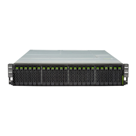
Starting up and operation 6.1.2 Front overview with CX2560 M4 / CX2570 M4 server nodes Figure 19: Configuration with 24x 2.5" HDDs (example) Pos. Component Operating panel for server node 1 Operating panel for server node 2 Operating panel for server node 3 Operating panel for server node 4 HDD bays for server node 1 HDD bays for server node 2... -
Page 55: Rear Overview With Cx2550 M4 Or Cx2560 M4 Server Nodes
6.1.3 Rear overview with CX2550 M4 or CX2560 M4 server nodes Figure 20: PRIMERGY CX400 M4 server enclosure rear with CX2550 M4 or CX2560 M4 server nodes Pos. Component Installation bay 1 for CX2550 M4 or CX2560 M4 server nodes... -
Page 56: Rear Overview With Cx2570 M4 Server Nodes
Starting up and operation 6.1.4 Rear overview with CX2570 M4 server nodes Figure 21: PRIMERGY CX400 M4 server enclosure rear with CX2570 M4 server nodes Pos. Component Installation bay 1/2 for CX2570 M4 server nodes Installation bay 3/4 for CX2570 M4 server nodes... -
Page 57: Controls And Indicators
Starting up and operation Controls and indicators 6.2.1 Front of the server enclosure Figure 22: Controls and indicators on the front panel Pos. Component Related to: PSU CSS indicator server enclosure Fan CSS indicator server enclosure Global error indicator server enclosure AC connected indicator server enclosure Global error indicator... -
Page 58: Indicators On The Front Panel (Enclosure-Related)
Starting up and operation 6.2.1.1 Indicators on the front panel (enclosure-related) PSU CSS indicator (orange) Lights up orange if a hot-plug PSU prefailure event has been detected that requires (precautionary) service intervention. Flashes orange if a hot-plug PSU error was detected that requires service intervention. - Page 59 Starting up and operation AC-connected indicator Lights up green if the server enclosure is connected to the mains. Operating Manual CX400 M4...
-
Page 60: Indicators On The Front Panel (Node-Related)
Starting up and operation 6.2.1.2 Indicators on the front panel (node-related) Power-on indicator (green) Does not light up when the server node is switched OFF. Lights up green when the server node is in power-on delay and while the system is in normal operation (S0). Flashes slowly (1/2 Hz) green when the iRMC S5 is initialized and is getting ready. - Page 61 Starting up and operation CSS indicator (orange) – Lights up orange if a prefailure event was detected for a CSS component that you can fix yourself (for reasons of precaution) with the CSS concept. – Flashes orange if an error was detected that you can fix yourself with the CSS concept.
-
Page 62: Id Card
Starting up and operation 6.2.1.3 ID card Figure 23: ID card You can pull out the ID card (1) as far as it will go and push it back again. The ID card contains various system information, such as the product name, serial number, order number, MAC addresses and DNS name (in Japan, only the serial number of the chassis and each node). -
Page 63: Indicators On The Hdds
Starting up and operation 6.2.1.4 Indicators on the HDDs Figure 24: Indicators on the 2.5 inch HDD modules HDD/SSD FAULT indicator (orange) (in conjunction with a RAID controller) – Does not light: no HDD error – Lights up: HDD Faulty or Rebuild Stopped (drive defective/needs replacing, a rebuild process was stopped or the HDD module is not correctly inserted) –... -
Page 64: Indicator On Hot-Plug Psu
Starting up and operation 6.2.2 Indicator on hot-plug PSU Figure 25: Indicator on hot-plug PSU Indicator on hot-plug PSU (two colors) Flashes green when the all server nodes is switched off, but AC voltage is present (standby mode). Lights up green when the one or more server nodes is switched on and functioning properly. -
Page 65: Switching The Multi-Node Server System On And Off
Furthermore, Fujitsu cannot be held responsible for any related damage, malfunction, or loss of data, etc. Be sure to wait for 10 seconds or more after shutdown before turning ●... - Page 66 Starting up and operation Switching the server node on Ê Press the On/Off button of the desired server node on the rear or on the front. Then the power-on indicator lights up green. – Starting up for the first time: For Japan, please refer to "...
- Page 67 Starting up and operation – After power failure The server node automatically reboots following a power failure (depending on the settings in the BIOS or in iRMC S5). – Power-on indicator override The server node can be switched off (hard power off) by holding down the On/Off button (approximately 4 - 5 seconds).
-
Page 68: Cleaning The Server Enclosure
Starting up and operation Cleaning the server enclosure CAUTION! Switch the server enclosure off and disconnect the power plugs from the properly grounded power outlets. Do not clean any interior parts yourself; leave this job to a service technician. Do not use any cleaning agents that contain abrasives or may corrode plastic. -
Page 69: Property And Data Protection
Property and data protection To protect the installed server nodes and data internally against unauthorized access, you can use the BIOS Setup security functions. BIOS setup security functions The Security menu in BIOS Setup offers various options for protecting your data from unauthorized access. - Page 70 Property and data protection Operating Manual CX400 M4...
-
Page 71: Troubleshooting And Tips
Troubleshooting and tips CAUTION! Follow the safety instructions in the "Safety notes and regulations" manual or " 安全上のご注意 " and in chapter "Important information" on page If a fault occurs, attempt to resolve it using the measures described: – in this chapter, –... -
Page 72: Drives Reported As "Dead" When Starting System
Troubleshooting and tips Drives reported as “dead” when starting system This error message can occur when the onboard SATA controller has RAID functionality or the server enclosure is equipped with a PCI RAID controller. RAID controller configuration incorrect Ê Check and correct the settings for the drives using the RAID controller utility. Added drive reported as defective RAID controller is not configured for this drive The drive was probably installed when the system was switched off.
Need help?
Do you have a question about the PRIMERGY CX400 M4 and is the answer not in the manual?
Questions and answers