Table of Contents
Advertisement
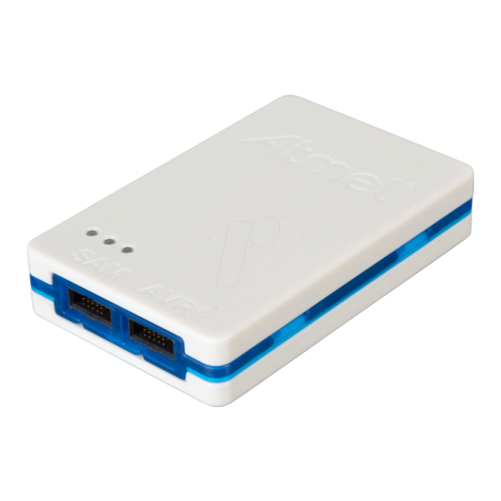
The Atmel-ICE Debugger
Atmel-ICE is a powerful development tool for debugging and programming
®
®
ARM
Cortex
-M based Atmel
On-Chip Debug capability.
It supports:
•
Programming and on-chip debugging of all Atmel AVR 32-bit
microcontrollers on both JTAG and aWire interfaces
•
Programming and on-chip debugging of all Atmel AVR XMEGA
devices on both JTAG and PDI 2-wire interfaces
•
Programming (JTAG, SPI, UPDI) and debugging of all Atmel AVR 8-bit
microcontrollers with OCD support on either JTAG, debugWIRE or
UPDI interfaces
•
Programming and debugging of all Atmel SAM ARM Cortex-M based
microcontrollers on both SWD and JTAG interfaces
•
Programming (TPI) of all Atmel tinyAVR
support for this interface
Consult the supported devices list in the Atmel Studio User Guide for a full
list of devices and interfaces supported by this firmware release.
Programmers and Debuggers
®
®
SAM and Atmel AVR
microcontrollers with
®
8-bit microcontrollers with
Atmel-42330C-Atmel-ICE_User Guide-10/2016
Atmel-ICE
USER GUIDE
®
family
Advertisement
Table of Contents

Related Manuals for Atmel Atmel-ICE


Summary of Contents for Atmel Atmel-ICE
-
Page 1: The Atmel-Ice Debugger
• Programming (TPI) of all Atmel tinyAVR 8-bit microcontrollers with support for this interface Consult the supported devices list in the Atmel Studio User Guide for a full list of devices and interfaces supported by this firmware release. Atmel-42330C-Atmel-ICE_User Guide-10/2016... -
Page 2: Table Of Contents
The Atmel-ICE Debugger....................1 1. Introduction........................ 5 1.1. Introduction to the Atmel-ICE....................... 5 1.2. Atmel-ICE Features........................5 1.3. System Requirements........................6 2. Getting Started with the Atmel-ICE................7 2.1. Full Kit Contents........................... 7 2.2. Basic Kit Contents........................7 2.3. PCBA Kit Contents........................8 2.4. - Page 3 EVTI / EVTO Usage.....................55 7.2. debugWIRE Targets........................55 7.2.1. debugWIRE Software Breakpoints................55 8. Release History and Known issues................. 57 8.1. Firmware Release History......................57 8.2. Known Issues Concerning the Atmel-ICE.................. 57 8.2.1. General........................57 Atmel Atmel-ICE [USER GUIDE] Atmel-42330C-Atmel-ICE_User Guide-10/2016...
- Page 4 8.2.2. Atmel AVR XMEGA OCD Specific Issues..............57 8.2.3. Atmel AVR - Device Specific Issues................58 9. Product Compliance....................59 9.1. RoHS and WEEE........................59 9.2. CE and FCC..........................59 10. Revision History.......................60 Atmel Atmel-ICE [USER GUIDE] Atmel-42330C-Atmel-ICE_User Guide-10/2016...
-
Page 5: Introduction
Introduction 1.1. Introduction to the Atmel-ICE Atmel-ICE is a powerful development tool for debugging and programming ARM Cortex-M based Atmel SAM and Atmel AVR microcontrollers with On-Chip Debug capability. It supports: • Programming and on-chip debugging of all Atmel AVR UC3 microcontrollers on both JTAG and aWire interfaces •... -
Page 6: System Requirements
The Atmel-ICE unit requires that a front-end debugging environment Atmel Studio version 6.2 or later is installed on your computer. The Atmel-ICE should be connected to the host computer using the USB cable provided, or a certified Micro-USB cable. Atmel Atmel-ICE [USER GUIDE]... -
Page 7: Getting Started With The Atmel-Ice
Getting Started with the Atmel-ICE 2.1. Full Kit Contents The Atmel-ICE full kit contains these items: • Atmel-ICE unit • USB cable (1.8m, high-speed, Micro-B) • Adapter board containing 50-mil AVR, 100-mil AVR/SAM, and 100-mil 20-pin SAM adapters • IDC flat cable with 10-pin 50-mil connector and 6-pin 100-mil connector •... -
Page 8: Pcba Kit Contents
Figure 2-2. Atmel-ICE Basic Kit Contents 2.3. PCBA Kit Contents The Atmel-ICE PCBA kit contains these items: • Atmel-ICE unit without plastic encapsulation Figure 2-3. Atmel-ICE PCBA Kit Contents 2.4. Spare Parts Kits The following spare parts kits are available: • Adapter kit •... -
Page 9: Kit Overview
Figure 2-4. Atmel-ICE Adapter Kit Contents Figure 2-5. Atmel-ICE Cable Kit Contents 2.5. Kit Overview The Atmel-ICE kit options are shown diagrammatically here: Figure 2-6. Atmel-ICE Kit Overview full kit basic kit PCBA kit adapter kit PCBA cable kit Atmel Atmel-ICE [USER GUIDE]... -
Page 10: Assembling The Atmel-Ice
2.6. Assembling the Atmel-ICE The Atmel-ICE unit is shipped with no cables attached. Two cable options are provided in the full kit: • 50-mil 10-pin IDC flat cable with 6-pin ISP and 10-pin connectors • 50-mil 10-pin mini-squid cable with 10 x 100-mil sockets Figure 2-7. Atmel-ICE Cables... -
Page 11: Opening The Atmel-Ice
Opening the Atmel-ICE Note: For normal operation, the Atmel-ICE unit must not be opened. Opening the unit is done at your own risk. Anti-static precautions should be taken. The Atmel-ICE enclosure consists of three separate plastic components - top cover, bottom cover, and blue belt - which are snapped together during assembly. - Page 12 Repeat the process on the other snapper holes, and the top cover will pop off. Figure 2-12. Opening the Atmel-ICE (1) Figure 2-13. Opening the Atmel-ICE (2)
-
Page 13: Powering The Atmel-Ice
2.8. Powering the Atmel-ICE The Atmel-ICE is powered by the USB bus voltage. It requires less than 100mA to operate, and can therefore be powered through a USB hub. The power LED will illuminate when the unit is plugged in. - Page 14 Once successfully installed, the Atmel-ICE will appear in the device manager as a "Human Interface Device". Atmel Atmel-ICE [USER GUIDE] Atmel-42330C-Atmel-ICE_User Guide-10/2016...
-
Page 15: Connecting The Atmel-Ice
MCU type - for example a SAM device mounted in an AVR STK 600 stack should use the AVR header. Various cabling and adapters are available in the different Atmel-ICE kits. An overview of connection options is shown. Figure 3-1. Atmel-ICE Connection Options... -
Page 16: Connecting To A Jtag Target
Use the 50-mil 10-pin flat cable (included in some kits) to connect directly to a board supporting this header type. Use the AVR connector port on the Atmel-ICE for headers with the AVR pinout, and the SAM connector port for headers complying with the ARM Cortex Debug header pinout. -
Page 17: Connecting To An Awire Target
Use the adapter board (included in some kits) to connect to a standard 50-mil aWire header. Connection to a custom 100-mil header The 10-pin mini-squid cable should be used to connect between the Atmel-ICE AVR connector port and the target board. Three connections are required, as described in the table below. -
Page 18: Connecting To A Pdi Target
Use the adapter board (included in some kits) to connect to a standard 50-mil PDI header. Connection to a custom 100-mil header The 10-pin mini-squid cable should be used to connect between the Atmel-ICE AVR connector port and the target board. Four connections are required, as described in the table below. -
Page 19: Connecting To A Debugwire Target
RESET pin. The debugWIRE OCD is capable of disabling itself temporarily (using the button on the debugging tab in the properties dialog in Atmel Studio), thus releasing control of the RESET line. The SPI interface is then available again (only if the SPIEN fuse is programmed), allowing the DWEN fuse to be un-programmed using the SPI interface. -
Page 20: Connecting To An Spi Target
Use the adapter board (included in some kits) to connect to a standard 50-mil SPI header. Connection to a custom 100-mil header The 10-pin mini-squid cable should be used to connect between the Atmel-ICE AVR connector port and the target board. Six connections are required, as described in the table below. -
Page 21: Connecting To A Tpi Target
Use the adapter board (included in some kits) to connect to a standard 50-mil TPI header. Connection to a custom 100-mil header The 10-pin mini-squid cable should be used to connect between the Atmel-ICE AVR connector port and the target board. Six connections are required, as described in the table below. -
Page 22: Connecting To An Swd Target
When using an STK600 or a board making use of the AVR JTAG pinout, the AVR connector port on the Atmel-ICE must be used. When connecting to a board, which makes use of the ARM JTAG pinout, the SAM connector port on the Atmel-ICE must be used. -
Page 23: Connecting To Data Gateway Interface
Connecting to Data Gateway Interface The Atmel-ICE supports a limited Data Gateway Interface (DGI) when debugging and programming is not in use. Functionality is identical to that found on Atmel Xplained Pro kits powered by the Atmel EDBG device. The Data Gateway Interface is an interface for streaming data from the target device to a computer. This is meant as an aid in application debugging as well as for demonstration of features in the application running on the target device. -
Page 24: On-Chip Debugging
A software breakpoint is a BREAK instruction placed in program memory on the target device. When this instruction is loaded, program execution will break and the OCD enters stopped mode. To continue execution a "start" command has to be given from the OCD. Not all Atmel devices have OCD modules supporting the BREAK instruction. -
Page 25: Jtag Physical Interface
SAM JTAG Pinout (Cortex-M debug connector) When designing an application PCB which includes an Atmel SAM with the JTAG interface, it is recommended to use the pinout as shown in the figure below. Both 100-mil and 50-mil variants of this pinout are supported, depending on the cabling and adapters included with the particular kit. - Page 26 TMS and TCK are connected in parallel; TDI and TDO are connected in a serial chain. • nSRST on the Atmel-ICE probe must be connected to RESET on the devices if any of the devices in the chain disables its JTAG port •...
-
Page 27: Connecting To A Jtag Target
Use the 50-mil 10-pin flat cable (included in some kits) to connect directly to a board supporting this header type. Use the AVR connector port on the Atmel-ICE for headers with the AVR pinout, and the SAM connector port for headers complying with the ARM Cortex Debug header pinout. -
Page 28: Swd Physical Interface
PCB, which uses a SAM device with SWD or JTAG interface, it is recommended to use the ARM pinout shown in the figure below. The SAM connector port on the Atmel-ICE can connect directly to this pinout. Figure 4-4. Recommended ARM SWD/JTAG Header Pinout... -
Page 29: Special Considerations
ARM core. The ERASE pin is NOT part of any debug header, and the Atmel-ICE is thus unable to assert this signal to unlock a device. In such cases the user should perform the erase manually before starting a debug session. -
Page 30: Atmel Avr Uc3 On-Chip Debug System
4.3.1. Atmel AVR UC3 On-chip Debug System The Atmel AVR UC3 OCD system is designed in accordance with the Nexus 2.0 standard (IEEE-ISTO ™ 5001 -2003), which is a highly flexible and powerful open on-chip debug standard for 32-bit microcontrollers. It supports the following features: •... - Page 31 • All devices must share a common ground, connected to GND on the Atmel-ICE probe • All devices must be operating on the same target voltage. VTG on the Atmel-ICE must be connected to this voltage. Atmel Atmel-ICE [USER GUIDE]...
-
Page 32: Connecting To A Jtag Target
Use the 50-mil 10-pin flat cable (included in some kits) to connect directly to a board supporting this header type. Use the AVR connector port on the Atmel-ICE for headers with the AVR pinout, and the SAM connector port for headers complying with the ARM Cortex Debug header pinout. -
Page 33: Awire Physical Interface
A special enable sequence is transmitted by the Atmel-ICE, which disables the default RESET functionality of the pin. When designing an application PCB, which includes an Atmel AVR with the aWire interface, it is recommended to use the pinout as shown in Figure 4-8. -
Page 34: Connecting To An Awire Target
Use the adapter board (included in some kits) to connect to a standard 50-mil aWire header. Connection to a custom 100-mil header The 10-pin mini-squid cable should be used to connect between the Atmel-ICE AVR connector port and the target board. Three connections are required, as described in the table below. -
Page 35: Special Considerations
Special Considerations JTAG interface On some Atmel AVR UC3 devices the JTAG port is not enabled by default. When using these devices it is essential to connect the RESET line so that the Atmel-ICE can enable the JTAG interface. aWire interface The baud rate of aWire communications depends upon the frequency of the system clock, since data must be synchronized between these two domains. -
Page 36: Jtag Physical Interface
4.4.2. Connecting to a JTAG Target The Atmel-ICE is equipped with two 50-mil 10-pin JTAG connectors. Both connectors are directly electrically connected, but conform to two different pinouts; the AVR JTAG header and the ARM Cortex Atmel Atmel-ICE [USER GUIDE]... - Page 37 Use the 50-mil 10-pin flat cable (included in some kits) to connect directly to a board supporting this header type. Use the AVR connector port on the Atmel-ICE for headers with the AVR pinout, and the SAM connector port for headers complying with the ARM Cortex Debug header pinout.
-
Page 38: Spi Physical Interface
Use the adapter board (included in some kits) to connect to a standard 50-mil SPI header. Connection to a custom 100-mil header The 10-pin mini-squid cable should be used to connect between the Atmel-ICE AVR connector port and the target board. Six connections are required, as described in the table below. -
Page 39: Pdi
When designing an application PCB, which includes an Atmel AVR with the PDI interface, the pinout shown in the figure below should be used. One of the 6-pin adapters provided with the Atmel-ICE kit can then be used to connect the Atmel-ICE probe to the application PCB. -
Page 40: Updi Physical Interface
When designing an application PCB, which includes an Atmel AVR with the UPDI interface, the pinout shown below should be used. One of the 6-pin adapters provided with the Atmel-ICE kit can then be used to connect the Atmel-ICE probe to the application PCB. -
Page 41: Connecting To A Updi Target
This configuration effectively means that programming should be done before mounting the device. Important: The Atmel-ICE does not support 12V on the UPDI line. In other words, if the UPDI pin has been configured as GPIO or RESET the Atmel-ICE will not be able to enable the UPDI interface. 4.4.8. -
Page 42: Tpi Physical Interface
Use the adapter board (included in some kits) to connect to a standard 50-mil TPI header. Connection to a custom 100-mil header The 10-pin mini-squid cable should be used to connect between the Atmel-ICE AVR connector port and the target board. Six connections are required, as described in the table below. -
Page 43: Advanced Debugging (Avr Jtag /Debugwire Devices)
Atmel-ICE AVR port pins Target pins Mini-squid pin TPI pinout Pin 4 (VTG) Pin 5 (TMS) Pin 6 (nSRST) /RESET Pin 7 (not connected) Pin 8 (nTRST) Pin 9 (TDI) Pin 10 (GND) 4.4.11. Advanced Debugging (AVR JTAG /debugWIRE devices) I/O Peripherals Most I/O peripherals will continue to run even though the program execution is stopped by a breakpoint. -
Page 44: Megaavr Special Considerations
JTD bit. This will render code un-debuggable, and should not be done when attempting a debug session. If such code is already executing on the Atmel AVR device when starting a debug session, the Atmel-ICE will assert the RESET line while connecting. If this line is wired correctly, it will force the target AVR device into reset, thereby allowing a JTAG connection. -
Page 45: Avr Xmega Special Considerations
Be sure to check the "use external reset" checkbox in both the programming dialog and debug options dialog in order to allow the Atmel-ICE to assert the RESET line and re-enable the JTAG interface on devices which are running code which disables the JTAG interface by setting the JTD bit. -
Page 46: Debugwire Special Considerations
A bug existed on early versions of ATxmegaA1 devices that prevented the OCD from being enabled while the device was in certain sleep modes. There are two workarounds to re-enable OCD: • Go into the Atmel-ICE. Options in the Tools menu and enable "Always activate external reset when reprogramming device". •... -
Page 47: Debugwire Software Breakpoints
During a debug session, select the 'Disable debugWIRE and Close' menu option from the 'Debug' menu. DebugWIRE will be temporarily disabled, and Atmel Studio will use SPI programming to un-program the DWEN fuse. Having the DWEN fuse programmed enables some parts of the clock system to be running in all sleep modes. -
Page 48: Tinyx-Ocd (Updi) Special Considerations
CRCSCAN. (A simple chip erase will result in a blank flash with invalid CRC, and the part will thus still not boot.) Atmel Studio will automatically disable the CRCSCAN fuses when chip erasing a device in this state. - Page 49 If the UPDI pin is used as RESET or GPIO pin, all external drivers on the line must be disconnected during programming or debugging since they may interfere with the correct operation of the interface Atmel Atmel-ICE [USER GUIDE] Atmel-42330C-Atmel-ICE_User Guide-10/2016...
-
Page 50: Hardware Description
Hardware Description 5.1. LEDs The Atmel-ICE top panel has three LEDs which indicate the status of current debug or programming sessions. Table 5-1. LEDs Function Description Left Target power GREEN when target power is OK. Flashing indicates a target power error. Does not light up until a programming/debugging session connection is started. -
Page 51: Bottom Panel
5.3. Bottom Panel The bottom panel of the Atmel-ICE has a sticker which shows the serial number and date of manufacture. When seeking technical support, include these details. 5.4. Architecture Description The Atmel-ICE architecture is shown in the block diagram in Figure 5-1. -
Page 52: Atmel-Ice Target Connectors
At the heart of the Atmel-ICE main board is the Atmel AVR UC3 microcontroller AT32UC3A4256, which runs at between 1MHz and 60MHz depending on the tasks being processed. The microcontroller includes an on-chip USB 2.0 high-speed module, allowing high data throughput to and from the debugger. -
Page 53: Software Integration
AVR UC3 programming on aWire interface is clocked by the programmer. The optimal frequency is given by the SAB bus speed in the target device. The Atmel-ICE debugger will automatically tune the aWire baud rate to meet this criteria. Although it's usually not necessary the user can limit the maximum baud rate if needed (e.g. -
Page 54: Command Line Utility
Debug sessions on UC3 target devices over the aWire interface will be automatically tuned to the optimal baud rate by the Atmel-ICE itself. However, if you are experiencing reliability problems related to a noisy debug environment, some tools offer the possibility to force the aWire speed below a configurable limit. -
Page 55: Advanced Debugging Techniques
Atmel AVR UC3 Targets 7.1.1. EVTI / EVTO Usage The EVTI and EVTO pins are not accessible on the Atmel-ICE. However, they can still be used in conjunction with other external equipment. EVTI can be used for the following purposes: •... - Page 56 • Try to add or remove a small number of breakpoints at a time, to minimize the number of FLASH page write operations • If possible, avoid placing breakpoints on double-word instructions Atmel Atmel-ICE [USER GUIDE] Atmel-42330C-Atmel-ICE_User Guide-10/2016...
-
Page 57: Release History And Known Issues
General • The initial Atmel-ICE batches had a weak USB connector. A new revision has been made with a new and more robust USB connector. As an interim solution epoxy glue has been applied to the already produced units of the first version to improve the mechanical stability. -
Page 58: Atmel Avr - Device Specific Issues
8.2.3. Atmel AVR - Device Specific Issues • Cycling power on ATmega32U6 during a debug session may cause a loss of contact with the device Atmel Atmel-ICE [USER GUIDE] Atmel-42330C-Atmel-ICE_User Guide-10/2016... -
Page 59: Product Compliance
The Atmel-ICE and all accessories are manufactured in accordance to both the RoHS Directive (2002/95/EC) and the WEEE Directive (2002/96/EC). 9.2. CE and FCC The Atmel-ICE unit has been tested in accordance to the essential requirements and other relevant provisions of Directives: • Directive 2004/108/EC (class B) •... -
Page 60: Revision History
Added UPDI interface and updated Firmware Release History 42330B 03/2016 • Revised On-Chip Debugging chapter • New formatting of firmware release history in Release History and Known issues chapter • Added debug cable pinout 42330A 06/2014 Initial document release Atmel Atmel-ICE [USER GUIDE] Atmel-42330C-Atmel-ICE_User Guide-10/2016... - Page 61 DISCLAIMER: The information in this document is provided in connection with Atmel products. No license, express or implied, by estoppel or otherwise, to any intellectual property right is granted by this document or in connection with the sale of Atmel products. EXCEPT AS SET FORTH IN THE ATMEL TERMS AND...
- Page 62 Mouser Electronics Authorized Distributor Click to View Pricing, Inventory, Delivery & Lifecycle Information: Microchip ATATMEL-ICE ATATMEL-ICE-ADPT ATATMEL-ICE-PCBA ATATMEL-ICE-CABLE ATATMEL-ICE-BASIC...
Need help?
Do you have a question about the Atmel-ICE and is the answer not in the manual?
Questions and answers