Table of Contents
Advertisement
Quick Links
Advertisement
Chapters
Table of Contents

Related Manuals for Larson Davis SoundAdvisor NMS045


Summary of Contents for Larson Davis SoundAdvisor NMS045
- Page 1 SoundAdvisor Model NMS045 Permanent Noise Monitoring System Reference Manual...
- Page 2 Larson Davis SoundAdvisor Model NMS045 Permanent Noise Monitoring System Reference Manual INMS045.01...
- Page 3 For warranty information, refer to our Terms and Conditions of Sale on our we bsite at www.larsondavis.com/TermsConditions.aspx. Contact Larson Davis Website www.larsondavis.com Worldwide Corporate Headquarters Larson Davis - a PCB Piezotronics division 3425 Walden Avenue Depew, NY 14043-2495 USA Toll-free (in the US):888-258-3222 Phone:716-926-8243 USA fax:716-926-8215 E-mail: sales@larsondavis.com...
-
Page 4: Table Of Contents
Table of Contents Module 1 System Overview 1.1 Overview ................................1-1 1.2 NMS045 Features ..............................1-2 1.3 Components ................................1-2 1.4 Wiring Diagram ..............................1-4 Module 2 Getting Started 2.1 Overview ................................2-1 2.2 Preparing the Battery ............................2-1 2.3 Assembling the Solar Bracket ..........................2-2 2.4 Assembling Main Plate & Components ......................2-3 2.5 Preparing Cellular Service for the RV50X ......................2-3 2.6 Configuring SLM Settings On the 831C ......................2-9 Module 3... -
Page 5: Module 1 System Overview
Module 1 System Overview Overview ..........................1-1 NMS045 Features .........................1-2 Components ........................1-2 Wiring Diagram ........................1-4 1.1 Overview The SoundAdvisor Model NMS045 Permanent Noise Monitoring System is a mounted, permanent noise monitoring system used for long-term outdoor sound level monitoring. It is powered by one or two 12 V batteries which are charged by a solar panel or an AC connection. -
Page 6: Nms045 Features
1.2 NMS045 Features Acoustic Measurement The area sound is measured with the SoundAdvisor Model 831C sound level meter using a prepolarized microphone and preamplifier that are environmentally protected in a shroud. Power Options A solar panel can effectively charge the 12 V battery to power the system continuously without interruption. - Page 7 831C-045S/AC The SoundAdvisor Model NMS045 includes following components as a base for the NMS045 system: • SoundAdvisor Model 831C Sound Level Meter with options: • 831C-ELA • 831C-LOG • 831C-SW • Main plate • PRM2103-FF Preamplifier and microphone • EPS2116 Environmental Protection Shroud •...
-
Page 8: Wiring Diagram
1.4 Wiring Diagram The following diagram shows the system with all available options, including the two power options: solar and AC. At least one battery is needed to run the system. FIGURE 1-2 System Wiring Diagram Weather/Wind Sensor PRM2103-FF Microphone and Preamplifier Cellular Antennas CBL222-20... - Page 9 Figure 1-3 is color coded to show the options and their components: • Blue - COM-RV50X-045NA/EU:APAC Cellular Gateway • Purple - SEN031-045, SEN032-045 Weather/Wind System • Green - Solar Powered System • Orange - AC Powered System • Pink - Batteries, one or two •...
-
Page 10: Module 2 Getting Started
Module 2 Getting Started Overview ..........................2-1 Preparing the Battery ......................2-1 2.2.1 Charging the Battery .....................2-2 Assembling the Solar Bracket .....................2-2 Assembling Main Plate & Components ................2-3 Preparing Cellular Service for the RV50X ................2-3 2.5.1 Installing the SIM Card ..................2-4 2.5.2 Configuring for Remote Communication ............ -
Page 11: Assembling The Solar Bracket
2.2.1 Charging the Battery If you are using two 12 V batteries ensure both batteries are CAUTION fully charged before installation. You risk blowing a fuse if one is depleted and one is charged. The batteries cannot have more than 1 V difference in charge when connected. -
Page 12: Assembling Main Plate & Components
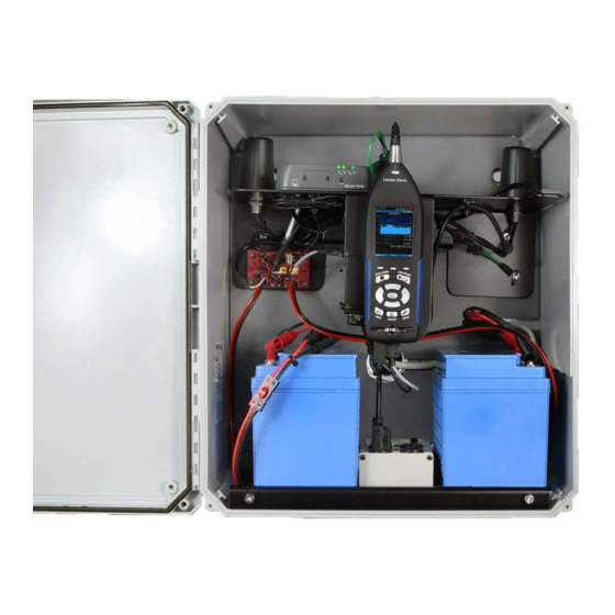
2.4 Assembling Main Plate & Components The 831C-045 ships partially assembled. Mount the separate components of the 831C-045 as shown in Figure 2-3 prior to field installation. The 831C SLM mounts with 2 front screws. The cables can be left bundled together. FIGURE 2-3 831C-045 Assembly RV50X Gateway... -
Page 13: Installing The Sim Card
Send the SIM card to Step 1 Using the Phillips #0 screwdriver, unscrew the two screws TRY THIS Larson Davis and have the holding the front SIM card door closed. system configured before Step 2 Insert your card into to RV50X Sim Slot 1 (the top slot). - Page 14 Step 1 Ensure the gateway is connected to the antennas. They are connected to the ports marked Diversity and Cellular. FIGURE 2-5 RV50X Peripherals Step 2 Connect the system to a power source. Choose one of the following options: • Connect a 12 V battery to the power block on the connection line marked Power Block using the CBL231.
- Page 15 FIGURE 2-7 WAN/Cellular Step 8 Enter the APN provided by your cellular provider in the User Entered APN. Step 9 Click Apply, then click the Reboot button. Step 10 Login again, and navigate to the Status tab. Step 11 From the left pane, select the Home section. The Network State should say Network Ready if everything is correct.
-
Page 16: Configuring The Intrusion Detection
2.5.3 Configuring the Intrusion Detection This feature is only If the RV50X was purchased through Larson Davis and the SIM was TAKE NOTE available with the COM- provided to the factory, you can skip to section 2.5.3 "Configuring the RV50X-045NA/EU:APAC Intrusion Detection". - Page 17 message that will be included in the alert. When finished click Apply. FIGURE 2-10 Intrusion Detection Settings Step 5 Navigate Services Email (SMTP). These settings are to determine where the emails are coming from. The following shows an example unsecured Gmail account. Contact your IT professional for more information on your specific communication needs.
-
Page 18: Configuring Slm Settings On The 831C
and turn Allow less secure apps to ON. For other SMTP accounts, contact your IT professional. Step 9 Send a test email. Navigate Events Reporting Intrusion Detection in the RV50X ACEmanager. 2.5.4 Enabling the Trusted IP (Friends) List We strongly recommend that you complete the following process to disable remote access from unknown IP addresses. - Page 19 NMS044 system. To determine the shutoff voltage, use Table 2.1: Table 2.1 Shutoff Voltage Battery Shutoff Voltage The LiFePo Battery (12V 45Ahr) 12.0 V The SLA Battery (12V 35Ahr) 10.8 V Step 4 Navigate to the Preferences tab, set Auto-Store to Store, and click Close and Yes to save your changes.
-
Page 20: Module 3 Field Installation
The steps in this module describe installing the 831C-045 contents, which is done after the pole and box have been installed. For instructions on pole and box installations, contact Larson Davis. Complete each section in this module to correctly install the 831C-045 contents. -
Page 21: Installing The Nms045 On The Trp019 Pole
• 3.3.1 "Positioning the Pole Tip-Down" • 3.3.2 "Installing the Battery and Main Plate" • 3.3.3 "Routing Cables in the Pole" • 3.3.4 "Connecting the Preamplifier, Microphone, and Protec- tion" • 3.3.5 "Installing Components in the Box" • 3.3.6 "Powering the System On" 3.3.1 Positioning the Pole Tip-Down Step 1 Attach the 2 carabiners to either side of the rope. -
Page 22: Installing The Battery And Main Plate
Do not stand Step 4 Using the rope attached to the top ring, pull gently until CAUTION underneath the pole. the top half of the pole tip down. The rope prevents the pole from hitting the ground. Ensure you create adequate clearance for the pole to tip down so the pole does not contact electrical wires or surfaces. -
Page 23: Routing Cables In The Pole
FIGURE 3-4 Battery placement Two battery placement One battery placement Step 2 Place the main plate on the outside of the box, on the battery plate shoulder screws. The main plate should have all the components installed, TAKE NOTE and the gateway network ready. For these steps, see 2.4 "Assembling Main Plate &... - Page 24 FIGURE 3-6 Cable Protection FIGURE 3-7 Cables in TRP019 CBL233-12 Solar Outlet (red) CBL222-20 Signal Outlet (green) CBL229-20 Weather Outlet (blue) CBL222-20 & CBL229-20 route through top hole CBL233-12 route through bottom Step 1 Open the back of the pole as shown in Figure 3-8 "Back of Pole".
- Page 25 FIGURE 3-8 Back of Pole Step 2 Feed the CBL222-20 through the top hole in the back of the box until it is on the outside of the pole on the opposite side. See point A in Figure 3-7 "Cables in TRP019". Step 3 Feed the cable up the pole and out at the bend at point B.
-
Page 26: Connecting The Preamplifier, Microphone, And Protection
3.3.4 Connecting the Preamplifier, Microphone, and Protection Step 1 Remove the rubber cap from the top of the preamplifier. Step 2 Place microphone on preamplifier, and gently screw together until hand tight. Step 3 Hold the EPS2116 windscreen and bird spike together, and unscrew from the top. -
Page 27: Installing Components In The Box
FIGURE 3-11 EPS2116 Threading Thread the CBL222-20 cable up through the base and top of the EPS2116. Align red dots on bottom of preamplifier to top of CBL222-20, gently push together until mounted. (This step can be done after the EPS2116 is mounted to the pole, but attaching it now prevents the CBL222-20 from slipping into the pole). - Page 28 FIGURE 3-12 CBL222-20 Connection Step 2 Lift plate off of shoulder screws, then mount onto the shoulder screws on the back plate. FIGURE 3-13 Plate On Back Shoulder Screws Shoulder screws location on back plate Step 3 For AC: connect PSA040 to the surge suppressor (as shown in Figure 3-14) For solar: connect the solar charger to the control power block on the line called Power Block.
- Page 29 FIGURE 3-14 PSA040 to Surge Suppressor PSA040 (AC only) After connection, you can tie the cord out of the way with provided zip tie as shown. Surge suppressor Step 4 Connect the battery to the power block on the line called Power Block.
-
Page 30: Powering The System On
FIGURE 3-16 Components Installed 3.3.6 Powering the System On Once the battery is connected, the system powers on. The 831C power button 0 controls the power in the whole system. It is used to turn off and on the NMS045. NMS045 Reference Manual Installing the NMS045 on the TRP019 Pole 3-11... -
Page 31: Performing A Field Operational Check
3.4 Performing a Field Operational Check Follow these steps prior to leaving the installed system: 3.4.1 Verifying Battery is Charged/Charging AC Power Charging You will know the battery is fully charged when the LED on the PSA040 power charger is green. An orange LED indicates the battery is charging. -
Page 32: Securing The Pole
Keys for removing locks, and tools for opening box and putting Preamplifiers. the pole in the tip down position. • Calibrator like the Larson Davis CAL200 or CAL250. • Access to the 831C in the box, or a mobile device with Internet access. - Page 33 Step 4 Navigate Tools Calibrate on the 831C sound level meter. Alternatively, you can access this page using remote communication on a mobile device. See "Connecting to the 831C Remotely" on page 3-12. Step 5 Select calibrator from the drop-down list. Click Edit Settings if calibrator settings need to be modified.
- Page 34 Step 9 Carefully remove calibrator from microphone. Click Calibration Step 10 When calibration process is complete, assemble the TRY THIS History to view either windscreen and bird spike back on to microphone. acoustic calibration or calibration check summaries. NMS045 Reference Manual Calibrating the 831C 3-15...
-
Page 35: Module 4 Options Installation
Module 4 Options Installation Overview ..........................4-1 Required Tools (not supplied) .................... 4-1 Solar Installation .........................4-1 Weather Installation ......................4-7 4.1 Overview The following options can be installed in conjunction with the steps in "Field Installation". 4.2 Required Tools (not supplied) The tools listed are a recommended to have available for installation. It is not a comprehensive list, and comparable substitutions can be made at your discretion. - Page 36 the SLP003 solar panel and mount. See 2.3 "Assembling the Solar Bracket" on page 2-2. Step 4 Establish which side of the pole is best for the solar panel to face. It should face an unobstructed view of the sun’s main trajectory in the sky.
- Page 37 Step 6 The solar cable CBL233-12 will connect the panel with the charge controller. Feed the cable down the pole to the bottom hole in the box. FIGURE 4-2 Feed Cable Down Pole Feed cable through hole, out the bend, then down into the box.
- Page 38 To disconnect the Step 8 Connect cables, ensuring they are completely seated. You TAKE NOTE solar connectors, use the will hear a small snap when they are connected. included ring tool. FIGURE 4-4 Connect Solar Cable to Panel Step 9 Feed CBL233-12 into the box through the bottom hole. Connect to solar charger on the area marked Panel.
- Page 39 correct cable ends, then tighten down. Black to negative, red to positive. FIGURE 4-5 CBL233-12 to Solar Charger Black to negative Red to positive Step 10 Connect CBL226-03 to the solar charger in the space marked Battery. Loosen the screws, insert the correct cable ends, then tighten down.
- Page 40 block on the line marked Power Block. After everything else is connected to the control power block, connect the battery to the line marked Power Block. Step 12 Check that the panel is charging the battery, see Step 10 "When calibration process is complete, assemble the windscreen and bird spike back on to microphone."...
-
Page 41: Weather Installation
4.4 Weather Installation Step 1 The pole should be in the tip down position. See 3.3.1 "Positioning the Pole Tip-Down" on page 3-2. Step 2 Feed CBL229-20 out the top hole in the box, up the pole and out at the bend. Then feed the cable down the second half of the pole and out the weather outlet hole. - Page 42 Step 3 Install the ADP101 on the weather arm top. Step 4 Place the gasket on the bottom of the weather arm. Feed CBL229-20 through the weather arm and adapter. FIGURE 4-9 Feed CBL229-20 Through Weather Arm Step 5 Bolt the weather arm to the pole with the gasket in place using a 9/16”...
- Page 43 Step 6 Connect the weather or wind sensor to the cable, push the slack back through the arm, and connect the sensor to the arm. FIGURE 4-11 Feed CBL229-20 Through Weather Arm Step 7 Ensure that north will point north once the pole is brought back into place.
- Page 44 FIGURE 4-13 Wind Station Example Step 8 Inside the box, route CBL229-20 through the top hole. Connect to the DVX008A, which should be routed through the top of the plate and into the USB hub. Route the Anderson connectors of the CBL220-20 through the top plate and into the control power block on the line marked Switched Power Block.
-
Page 45: Appendix A Additional Information
Appendix A Additional Information Physical Characteristics ......................A-1 NMS045 Power Information ....................A-4 A.2.1 Power Draw ......................A-4 A.2.2 Sunlight Hours ......................A-5 A.2.3 Alternative Solar Panel ..................A-5 A.2.4 Two Battery System ....................A-5 Shipping Information ......................A-5 A.3.1 Lithium Iron Phosphate Battery (LiFePo) ............A-5 LED Indicators ........................A-6 A.4.1 The 831C Sound Level Meter ................A-6 A.4.2... - Page 46 FIGURE A-1 Main Plate Dimensions NMS045 Reference Manual Physical Characteristics...
- Page 47 FIGURE A-2 EPS045 Dimensions 2.380 12.27 2.380 13.50 .531 2.125 18.12 10.34 8.72 2.500 10.000 19.69 NMS045 Reference Manual Physical Characteristics...
-
Page 48: Nms045 Power Information
FIGURE A-3 TRP019 Dimensions A.2 NMS045 Power Information The NMS045 System draws power from the connected battery that is charged by a solar panel or AC connection. A.2.1 Power Draw The power draw for the system depends on your settings, mode, and component options installed. -
Page 49: Shipping Information
used only as reference, for example as batteries age or operate at low temperature the runtime will be less: Table A.1 Typical Runtime One 45 Ah LiFePo One 35 Ah SLA Configuration Battery Battery (BAT019-045) (BAT020-045) NMS045 with Ethernet 8 days 6 days NMS045 with cellular 6 days... -
Page 50: Led Indicators
A.4 LED Indicators A.4.1 The 831C Sound Level Meter Table A.2 Measurement Status LED Indicators Measurement State Red LED 7 Green LED 9 Stopped with Reset Winking ***- Stopped Blinking **-*-* Paused Flashing *-*- Flashing -*-* Running Blinking **-*-* Waiting for valid Delayed ----* data to begin... - Page 51 Table A.3 RV50X LED Indicators (Sheet 2 of 2) Color/Pattern Description LED Power Saving Mode Signal Solid Green Good signal (equivalent to 4-5 bars) Solid Amber Fair signal (equivalent to 2-3 bars) Flashing Amber Poor signal (equivalent to 1 bar) If possible, move the gateway to a location with a better signal.
-
Page 52: Psa038 Genasun Solar Charger
A.4.3 PSA038 Genasun Solar Charger The solar charger has one bicolor status LED. When you first connect your charger to the battery, the LED should blink red then green. The LED blinks green to indicate that your charger is powered and charging, and the LED may blink red to indicate errors. -
Page 53: Connecting To G4 Ld Utility Over Tcp
A.5 Connecting to G4 LD Utility Over TCP While you can always connect directly to a PC from the 831C using the included USB cable, this section describes connecting via TCP/IP. Step 1 In G4 in the Me te rs Pane l, click the blue plus icon in-line with in-line with Meters. -
Page 54: Measurement Setup
defining trigger and exceedance levels, see section 6.2.6 in the SLM Model 831C Reference Manual. Other alerts, such as an Intrusion Detection alert are available through the RV50X. For more information about setting up this alert, see 2.5.3 "Configuring the Intrusion Detection" on page 2-7. To set up an exceedance alert notification, follow these steps: Step 1 Connect the 831C to a router with Internet access via WiFi or TCP. -
Page 55: Configuring Ld Settings For The Rv50X
The RV50X Gateway can only be a functioning communication device if it is configured with the correct settings. If you purchased a new RV50X from some one othe r than Larson Davis—or if it has be e n re se t to factory defaults—complete the following sections to configure your system for use with Larson Davis instruments. -
Page 56: Configuring Ld Settings Using The Template File
b. Select the name of your device, then select Firmware Package. c. If ne e de d, download and update the firmware according to the manufacturer's instructions. d. Log back in when the system is rebooted. Step 6 Change your password. Updating Your Password a. -
Page 57: Configuring Ld Settings Without The Template File
Step 7 Select Template in the top right. This ope ns the Te mplate upload window. Step 8 Click Choose File, se le ct the te mplate file “RV50XTemplateFile.xml” from the LD USB drive included with your system, then click Upload. If needed, you can also access the file from http://www.LarsonDavis.com Step 9 Select Apply. - Page 58 Step 3 Navigate to the Services tab, and in the le ft pane , se le ct the ACEmanager section. Step 4 Edit the values to match what is shown in Figure A-10 and click Apply. FIGURE A-10 Services - ACEmanager Step 5 In the left pane, click the Power Management section, and select Power Saving Mode.
- Page 59 Step 7 In the left pane, select Telnet/SSH Echo, set the value to Disable and click Apply. FIGURE A-12 Telnet/SSH Step 8 Select the Location tab, then in the left pane, select Global Settings. Step 9 From the Location Service drop-down, choose Enable. Step 10 Set the TCP Location Port to 9494, and click Apply.
- Page 60 Step 11 In the left pane, select Local/Streaming, modify the values to match Figure A-14, and click Apply. FIGURE A-14 Local/Streaming Configuration Values Step 12 Navigate to the Events Reporting tab. Step 13 Change the Action Name to be Intrusion Detection, and the Action Type to be Email.
- Page 61 Step 15 Navigate to the Serial tab, select Disable from the Serial Port drop- down menu, and click Apply. FIGURE A-16 Serial Port Settings Step 16 Navigate to the LAN tab, and in the left pane, select the USB section. Step 17 Verify that the settings are as shown in Figure A-17, and click Apply.
- Page 62 FIGURE A-18 After this change you will not be able to connect to the gateway with a TAKE NOTE wired Ethernet connection. If you need to restore the wired connection without connecting to the gateway through the cellular connection, do a hard reset on the gateway.
- Page 63 Larson Davis - a PCB Piezotronics division LarsonDavis.com P/N INMS045.01 Rev C ©2019 PCB Piezotronics, Inc. Worldwide Corporate Headquarters Toll-free (in the US): 888-258-3222 3425 Walden Avenue Phone: 716-926-8243 Depew, NY 14043-2495 USA USA fax: 716-926-8215 E-mail: sales@larsondavis.com NMS045 Reference Manual...
- Page 64 NMS045 Reference Manual...
Need help?
Do you have a question about the SoundAdvisor NMS045 and is the answer not in the manual?
Questions and answers