
Subscribe to Our Youtube Channel
Related Manuals for TSI Instruments HM675


Summary of Contents for TSI Instruments HM675
- Page 1 HYDRONIC MANOMETER MODEL HM675 TSI Alnor HM675 Hydronic Manometer OWNER’S MANUAL P/N 6006821, REVISION A MAY 2013 netzerotools.com...
- Page 2 netzerotools.com netzerotools.com...
- Page 3 HYDRONIC MANOMETER MODEL HM675 OWNER’S MANUAL P/N 6006821, REVISION A MAY 2013 netzerotools.com...
-
Page 4: Manual History
M a n u a l H i s t o r y The following is a manual history of the Hydronic Manometer Model HM675 Owner’s Manual (P/N 6006821). Revision Date May 2013 Hydronic Manometer Model HM675 netzerotools.com... -
Page 5: Warranty
netzerotools.com W a r r a n t y 6006821 / Revision A / May 2013 Part Number ©TSI Incorporated / 2013 / All rights reserved. Copyright Seller warrants the goods sold hereunder, under normal use and service as Limitation of Warranty described in the operator's manual, shall be free from defects in workmanship and and Liability material for twenty-four (24) months, or if less, the length of time specified in the... - Page 6 Officer of Seller. CompuDat is a trademark of TSI Incorporated. TSI and the TSI logo are registered Trademarks trademark of TSI Incorporated. Microsoft, Excel, Windows, and Vista are registered trademarks of Microsoft Corporation. Hydronic Manometer Model HM675 netzerotools.com...
-
Page 7: Table Of Contents
netzerotools.com C o n t e n t s Manual History ..................0-ii Warranty ....................0-iii About This Manual ................. 0-iii Formatting and Typography ............... 0-iii Technical Assistance—Help! ............. 0-iii Safety Information ................... 0-v Labels ....................0-v Description of Caution/Warning Symbols .......... 0-vi Caution .................... - Page 8 Troubleshooting .................. 3-4 Technical Contacts ................3-5 APPENDIX A Specifications ..............A-1 APPENDIX B Compliance ..............B-1 Hydronic Manometer Model HM675 netzerotools.com...
-
Page 9: About This Manual
T e c h n i c a l A s s i s t a n c e — H e l p ! For technical assistance or questions about the instrument or this manual, or if the HM675 Hydronic Manometer needs repair or recalibration, call Technical Support. - Page 10 (This page intentionally left blank) Hydronic Manometer Model HM675 netzerotools.com...
-
Page 11: Safety Information
S a f e t y I n f o r m a t i o n Carefully read each of the following safety warnings prior to using the HM675 Hydronic Manometer. This section gives instructions to promote safe and proper handling of the HM675 Hydronic Manometer. -
Page 12: Description Of Caution/Warning Symbols
HM675 Hydronic Manometer. W A R N I N G Never use the HM675 Hydronic Manometer or accessories on potable water systems or other systems which may be used to convey fluids for human or animal consumption. - Page 13 C a u t i o n Never use the HM675 Hydronic Manometer to measure the pressure of volatile, flammable, or otherwise hazardous fluids or gasses. The instrument is not designed to be intrinsically safe, nor is it designed for use with caustic or corrosive chemicals.
- Page 14 “Water Hammer.” Water Hammer is a fast moving shock wave of pressure caused by sudden changes in the system such as a valve being opened or closed or a pump being turned on or off. viii Hydronic Manometer Model HM675 netzerotools.com...
-
Page 15: Chapter 1 Introduction
I n t r o d u c t i o n ... -
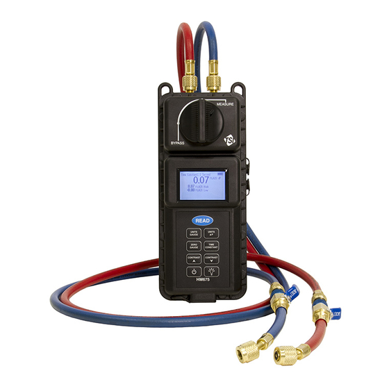
Page 16: Instrument Description
I n s t r u m e n t D e s c r i p t i o n (2) Female to Male Parallel Pipe Threads (2) Female ... -
Page 17: Unpacking
As you unpack the instrument and accessories, check the components against your packing list. If any parts are missing or damaged, notify TSI immediately. Tables 1-1 and 1-2 list available standard and optional components for the HM675 Hydronic Manometer. Table 1-1 Standard Components Item Part No. - Page 18 (This page intentionally left blank) Hydronic Manometer Model HM675 netzerotools.com...
-
Page 19: Keypad
I n s t r u m e n t O p e r a t i o n K e y p a d READ READ UNITS UNITS GAUGE GAUGE High Low P UNITS ΔP UNITS ∆P Note ... -
Page 20: Powering The Instrument
P o w e r i n g t h e I n s t r u m e n t The HM675 Hydronic Manometer can be powered by four (4) AA-size batteries (alkaline or rechargeable NiMH) or the AC adapter. -
Page 21: Battery Installation
Do not connect the AC adapter or car adapter provided with the battery optional charger (801093) or any other AC adapter to the HM675/685. Using any other power cable or power supply may cause damage to the device and void the warranty. -
Page 22: Battery Charging
Do not use Lithium batteries in this instrument. Fire, explosions, or other hazards may result. C a u t i o n Never plug into the instrument any power supply other than the one provided with the instrument. Hydronic Manometer Model HM675 netzerotools.com... - Page 23 C a u t i o n Never use Alkaline and NiMH batteries together on the same instrument. The HM675 Hydronic Manometer allows for internal charging of AA-size type NiMH (only) batteries. Charging of the batteries is initiated as follows: 1.
-
Page 24: Zeroing The Manometer
Z e r o i n g t h e M a n o m e t e r Zeroing the Gauge Pressure Sensor High P MEASURE ZERO GAUGE Notes: Zeroing the Differential Pressure Sensor Measurement Screen BYPASS MEASURE... -
Page 25: Connecting The Manometer To The Test Points
netzerotools.com Notes: Any pressures applied to the hoses will not affect the dP zeroing function. This feature allows for successful zeroing of the differential pressure sensor while maintaining connections to the system under test. Zeroing of the differential pressure sensor is initiated any time the valve handle has been turned to the BYPASS position with the meter turned on. -
Page 26: Attaching The Hoses To The Test Points
P e r f o r m i n g P r e s s u r e M e a s u r e m e n t s The HM675 Hydronic Manometer allows for simultaneous measurement and display of the High-side gauge and Differential pressure. The calculated Low-side gauge pressure is also displayed. -
Page 27: Continuous Measurements
P e r f o r m i n g T e m p e r a t u r e M e a s u r e m e n t s The accessory temperature probe is an optional tool for the HM675 Hydronic Manometer. -
Page 28: Disconnecting The Manometer From The Test Points
C a u t i o n Exercise caution in using the HM675 Hydronic Manometer near electrical equipment. Water spray associated with purging or disconnecting hoses presents a potential risk of damage to such equipment. - Page 29 netzerotools.com 5. Turn the valve handle on the manometer to the BYPASS position. 6. Turn the shut-off ball valve on the Low pressure (blue) hose to the open position to discharge the pressurized fluid out of the open end of the Low pressure (blue) hose.
- Page 30 (This page intentionally left blank) 2-12 Hydronic Manometer Model HM675 netzerotools.com...
-
Page 31: Routine Maintenance
M a i n t e n a n c e a n d Tr o u b l e s h o o t i n g I M P O R T A N T R o u t i n e M a i n t e n a n c e Draining the Hoses Reference Chapter 2, "Disconnecting the Manometer from the Test Points"... -
Page 32: In-Line Flow Restrictor
4. Turn the valve handle on the manometer to the MEASURE position. 5. Hold the manometer with the pressure ports directed downward to allow liquid to drain from the unit. Note: The HM675 Hydronic Manometer should be stored with the valve handle in the MEASURE position. In-Line Flow Restrictor The blue and red hose assemblies include flow restrictors. -
Page 33: Calibration
C a l i b r a t i o n TSI recommends that the HM675 Hydronic Manometer receive an annual calibration. TSI will verify calibration of the instrument and re-issue a certificate of calibration with traceability to NIST. This “annual checkup”... -
Page 34: Troubleshooting
Error Message Possible Causes & Corrective Action "Saved Pressure Zero” There was a problem with a pressure zero reading read from memory. Differential pressure and gauge pressure should both be re-zeroed. Hydronic Manometer Model HM675 netzerotools.com... -
Page 35: Technical Contacts
T e c h n i c a l C o n t a c t s ... - Page 36 (This page intentionally left blank) Hydronic Manometer Model HM675 netzerotools.com...
- Page 37 A P P E N D I X A S p e c i f i c a t i o n s Model HM675 Hydronic Manometer specifications are as follows (specifications are subject to change without notice). Range Differential Pressure ....
- Page 38 2-year factory warranty Accuracy statement applies from 0 to 250 psi (0 to 1724 kPa). The minimum battery life stated will occur after the NiMH batteries have been recharged 2 to 3 times after initial charge. Hydronic Manometer Model HM675 netzerotools.com...
- Page 39 C o m p l i a n c e CE Marking RoHS Marking...
- Page 40 (This page intentionally left blank) Hydronic Manometer Model HM675 netzerotools.com...
- Page 41 netzerotools.com netzerotools.com...
Need help?
Do you have a question about the HM675 and is the answer not in the manual?
Questions and answers