Table of Contents
Advertisement
Quick Links
Advertisement
Table of Contents
Troubleshooting

Subscribe to Our Youtube Channel
Related Manuals for TSI Instruments ALNOR HM670


Summary of Contents for TSI Instruments ALNOR HM670
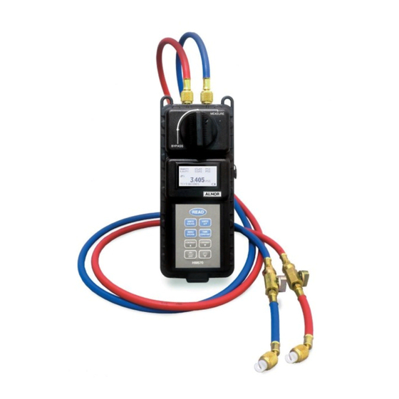
- Page 1 Hydronic Manometers Hydronic Manometer Model HM670 Owner’s Manual...
- Page 2 LIMITATION OF WARRANTY AND LIABILITY Copyright© TSI Incorporated / 2007-2016 / All rights reserved. Address TSI Incorporated / Alnor Products / 500 Cardigan Road / Shoreview, MN 55126 / USA Telephone No. Fax No 651 490-2811 / 800 874 2811 (651) 490-3824 LIMITATION OF WARRANTY AND LIABILITY (effective June 2011) (For country-specific terms and conditions outside of the USA, please visit www.tsi.com.)
-
Page 3: Table Of Contents
CONTENTS About This Manual ............................. iii Formatting and Typography ........................iii Technical Assistance—Help! ........................iii Chapter 1. Safety ............................1 Safety Warnings ............................. 1 Chapter 2. Introduction ..........................3 Instrument Description ..........................3 Unpacking ............................... 4 Chapter 3. Instrument Operation ....................... 5 Keypad .............................. -
Page 5: About This Manual
About This Manual ® This manual explains how to set up, operate and maintain the Alnor HM670 Hydronic Manometer. Read it thoroughly before using the instrument. Formatting and Typography Step-by-step instructions are numbered in boldface type: 1, 2, 3, etc., set flush-left against the margin. - Page 6 (This page intentionally left blank)
-
Page 7: Chapter 1. Safety
Chapter 1. Safety Safety Warnings Carefully read each of the following safety warnings prior to using the HM670 Hydronic Manometer. Never use the HM670 Hydronic Manometer or accessories on potable water systems or other systems which may be used to convey fluids for human or animal consumption. ... - Page 8 (This page intentionally left blank) HM670 Hydronic Manometer...
-
Page 9: Chapter 2. Introduction
Chapter 2. Introduction The HM670 Hydronic Manometer is an easy-to-use instrument designed for the accurate measurement of pressure in non-potable water and air systems. Features of the manometer include the following: Single-function keys for ease of use Simultaneous measurement and display of High-side gauge and Differential pressure ... -
Page 10: Unpacking
Unpacking As you unpack the instrument and accessories, check the components against your packing list. If any parts are missing or damaged, notify Alnor immediately. Tables 1 and 2 list available standard and optional components for the HM670 Hydronic Manometer. Table 1: Standard Components Item Part No. -
Page 11: Chapter 3. Instrument Operation
Chapter 3. Instrument Operation Keypad Each key and its function is described below. READ Pressing the READ key initiates taking a time-averaged reading based on the current setting of the time constant (TC). Upon taking the reading, the values are displayed on-screen for a period of ten (10) seconds or until the READ key has been pressed again. -
Page 12: Measurement Screen
Press the BACKLIGHT key to turn the display’s backlighting on or off. Note: Backlighting has a significant impact on battery life. Use backlighting only when working in areas where you cannot read the display with existing light. Measurement Screen *Shown with the accessory temperature probe attached High-Side Gauge Pressure Low-Side Gauge... -
Page 13: Installing The Batteries
Installing the Batteries To install/replace the batteries: 1. Turn the manometer off and locate the battery cover on the back of the unit. 2. Loosen the screw on the battery compartment cover and lift to remove. 3. Remove the battery holder. Tapping the backside of the meter against your hand may help in removing the battery holder. -
Page 14: Zeroing The Manometer
Zeroing the Manometer The HM670 Hydronic Manometer is equipped with both a gauge and differential pressure sensor, allowing for simultaneous measurement and display of High-side gauge and Differential pressure. The gauge and differential pressure sensors are zeroed independently of one another. Zeroing the Gauge Pressure Sensor To ensure the most accurate gauge pressure (High P) measurements, the HM670 gauge pressure sensor should be zeroed prior to taking readings on each new system. -
Page 15: Bleeding The Entrained Air
Bleeding the Entrained Air To ensure the most accurate pressure measurements, all entrained air within the hoses should be purged as follows: 1. Turn the shut-off ball valve on both the High and Low pressure hoses to the closed position. 2. -
Page 16: Continuous Pressure Measurements
Differential Pressure The Differential pressure measurement is indicated as dP on the manometer display. Continuous Pressure Measurements The HM670 Hydronic Manometer makes and displays continuous pressure measurements whenever the manometer is turned on, with the exception of when the READ key is pressed. The displayed readings are averaged measurements taken over the sampling period as defined by the current time constant setting. - Page 17 Note: If additional measurements at another location/system containing the same fluid are to be made, it is not necessary to proceed to step 4 and drain the fluid entrained within the hoses at this time. The fluid remaining within the hoses will help minimize the time necessary to bleed entrained air prior to making subsequent measurements.
- Page 18 (This page intentionally left blank) HM670 Hydronic Manometer...
-
Page 19: Chapter 4. Maintenance And Troubleshooting
Chapter 4. Maintenance and Troubleshooting The HM670 Hydronic Manometer has been designed to provide long-term field use with minimum required maintenance. As with any precision electronic device, however, proper care, maintenance, and handling will further ensure its accurate and reliable operation. Routine Maintenance The following guidelines should be followed whenever storing the HM670 Hydronic Manometer: Draining the Hoses... -
Page 20: Cleaning The In-Line Pressure Snubbers
Cleaning the In-line Pressure Snubbers The HM670 Hydronic Manometer is equipped with in-line pressure snubbers upstream of the shut-off ball valve on both the High and Low pressure hoses. These pressure snubbers should be flushed periodically with clean water to minimize potential clogging. 1. -
Page 21: Calibration
Calibration TSI recommends that the HM670 Hydronic Manometer receive an annual calibration. TSI can also verify calibration of the instrument and re-issue a certificate of calibration with traceability to NIST. This “annual checkup” helps to ensure the specified accuracy of the instrument is maintained. To calibrate the instrument, please ship TSI the complete package that includes the meter and accessory temperature probe. - Page 22 The following table lists error codes which can be displayed should the instrument detect a problem. Should any of these error codes recur repeatedly, the instrument should be returned to the factory for servicing. Error Code Possible Causes RTC CODE: Problem detected in reading or setting the time and date.
-
Page 23: Specifications
Specifications* Range Differential Pressure ..-300 to 300 psi (-2068 to 2068 kPa) Gauge Pressure....-20 to 300 psi (-138 to 2068 kPa) (-40 to 610 in. Hg) Operating Temperature ..40 to 100°F (4 to 38°C) electronics Storage Temperature ..0 to 140°F (-18 to 60°C) Temperature Probe** .. - Page 24 P/N 1980517 Rev E Copyright © 2016 by TSI Incorporated Printed in U.S.A.
Need help?
Do you have a question about the ALNOR HM670 and is the answer not in the manual?
Questions and answers