Table of Contents
Advertisement
Quick Links
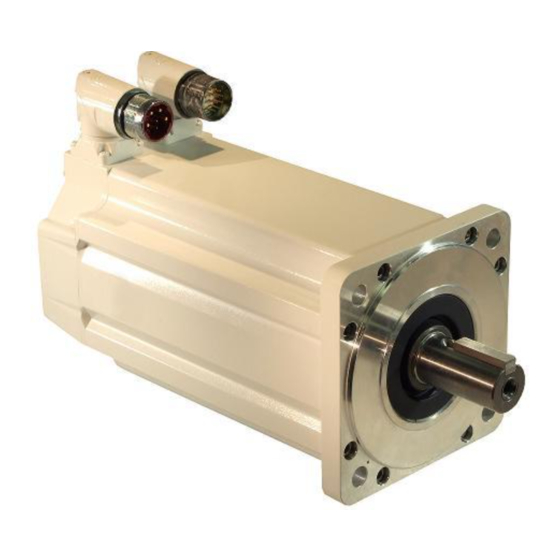
MP-Series Food Grade Servo Motor with
100 mm to 165 mm Frame Size
Catalog Numbers MPF-A310, MPF-A320, MPF-A330,
MPF-A430, MPF-A4530, MPF-A4540, MPF-A540,
MPF-B310, MPF-B320, MPF-B330, MPF-B430,
MPF-B4530, MPF-B4540, MPF-B540
Topic
Installation Instructions
Page
2
3
4
8
8
9
12
15
17
20
22
25
26
Advertisement
Table of Contents

Related Manuals for Rockwell Automation MPF-A310


Summary of Contents for Rockwell Automation MPF-A310
-
Page 1: Table Of Contents
Installation Instructions MP-Series Food Grade Servo Motor with 100 mm to 165 mm Frame Size Catalog Numbers MPF-A310, MPF-A320, MPF-A330, MPF-A430, MPF-A4530, MPF-A4540, MPF-A540, MPF-B310, MPF-B320, MPF-B330, MPF-B430, MPF-B4530, MPF-B4540, MPF-B540 Topic Page Important User Information Catalog Number Explanation Before You Begin... -
Page 2: Important User Information
In no event will Rockwell Automation, Inc. be responsible or liable for indirect or consequential damages resulting from the use or application of this equipment. -
Page 3: Catalog Number Explanation
MP-Series Food Grade Servo Motor Installation Instructions Catalog Number Explanation MP F - B 5 40 K - M J 7 2 B A FACTORY DESIGNATED OPTIONS = Standard MOUNTING FLANGE = IEC Metric - Oversized BRAKE = No Brake = 24V DC Brake CONNECTORS = Circular DIN, Right Angle, 180°... -
Page 4: Before You Begin
Change Connector Orientation. Only an authorized Allen-Bradley repair center shall service this item. Refer to Rockwell Automation Support for assistance to locate the nearest repair center. Failure to observe safety precautions could result in personal injury or damage to equipment. - Page 5 MP-Series Food Grade Servo Motor Installation Instructions • Inspect the motor and seals for damage or wear on a regular basis. If damage or excessive wear is observed, replace the item. • If desired, you may seal the motor front flange to the driven equipment by applying a bead of food grade RTV around the periphery of the joint between the motor and the machine surfaces.
- Page 6 MP-Series Food Grade Servo Motor Installation Instructions Using Couplings and Pulleys Mechanical connections to the motor shaft, such as couplings and pulleys, require a torsionally rigid coupling or a reinforced timing belt. The high dynamic performance of servo motors can cause couplings, pulleys, or belts to loosen or slip over time.
- Page 7 MP-Series Food Grade Servo Motor Installation Instructions Preventing Electrical Noise ElectroMagnetic Interference (EMI), commonly called electrical noise, can reduce motor performance. Effective techniques to counter EMI include filtering the AC power, use of shielded cables, separating signal cables from power wiring, and practicing good grounding techniques.
-
Page 8: Install The Motor
MP-Series Food Grade Servo Motor Installation Instructions Install the Motor All motors include a mounting pilot for aligning the motor on the machine. Preferred fasteners are stainless steel. The installation must comply with all local regulations and use equipment and installation practices that promote safety and electromagnetic compatibility. -
Page 9: Change Connector Orientation
MP-Series Food Grade Servo Motor Installation Instructions Change Connector Orientation You may rotate the connector housing up to 180 degrees. This lets you adjust the connector to a position that best protects the connection from possible environmental contaminates while providing cable access. Connectors are designed to be rotated into a fixed position during motor installation, and ATTENTION remain in that position without further adjustment. - Page 10 MP-Series Food Grade Servo Motor Installation Instructions Build and Route the Cables Knowledgeable cable routing and careful cable construction improves system performance. Build and install cables as described in these steps. 1. Keep wire lengths as short as physically possible. 2.
- Page 11 MP-Series Food Grade Servo Motor Installation Instructions Ground Shielded Signal Wires within a Power Cable Always connect the shield on any signal wire pair routed inside a power cable to the overall machine ground. If any shield on a power cable is not grounded, high voltage can be present on that shield. ATTENTION Make sure there is a connection to ground for all shield wires inside a power cable, and for the overall power cable shield.
-
Page 12: Mount The Motor
MP-Series Food Grade Servo Motor Installation Instructions Mount the Motor Follow these steps to mount the motor on a machine. 1. Provide sufficient clearance, heatsink mass, and air flow for the motor so it stays within the operating temperature range of 0…40 °C (32…104 °F). Do not enclose the motor unless cooling air is forced across the motor and keep other heat producing devices away from the motor. - Page 13 MP-Series Food Grade Servo Motor Installation Instructions Attach Motor Cables Follow these steps to attach the feedback, and power/brake cables after the motor is mounted. Make sure that cables are installed and restrained to prevent uneven tension or flexing at ATTENTION the motor-to-cable connections.
- Page 14 MP-Series Food Grade Servo Motor Installation Instructions 3. Carefully align the flat surface on the feedback or the power/brake cable plug (shown in the diagram) with the flat surface on the motor connector. The motor orientation shown is used to clearly show the alignment marker on IMPORTANT each cable socket.
-
Page 15: Connector Data
MP-Series Food Grade Servo Motor Installation Instructions Connector Data These tables identify pinouts for the feedback and the power with brake connectors. M23 Feedback Connector M23 Power with Brake Connector MPF-A3xx…MPF-A45xx, and MPF-A3xx…MPF-A45xx MPF-B3xx…MPF-B45xxx Sin+ Phase U Sin- Phase V Cos+ Phase W Cos-... - Page 16 MP-Series Food Grade Servo Motor Installation Instructions M23 Feedback Connector M40 Power with Brake Connector MPF-Bxxx (460V) and MPF-A5xx MPF-A5xx and MPF-B5xx Sin+ Phase U Sin- Phase V Cos+ Phase W Cos- Ground Data+ Data- Reserved Reserved +9V DC Common Reserved M23 Feedback Connector M40 Power/Brake Connector...
-
Page 17: Mounting Dimensions
MP-Series Food Grade Servo Motor Installation Instructions Mounting Dimensions The dimensions in the table are for non-brake motors. Footnotes provide tolerances for the common dimensions, and the additional dimensions specific to brake motors or features on specific motors. Publication MP-IN004D-EN-P — April 2009... - Page 18 MP-Series Food Grade Servo Motor Installation Instructions Motor (5), (6) Series L-LB MPF-A (in.) (in.) (in.) (in.) (in.) (in.) (in.) (in.) (in.) MPF-B 67.5 87.25 16.0 133.4 168.0 40.0 9.91 (2.66) (3.43) (0.629) (0.197) (0.118) (5.25) (6.62) (1.57) (0.39) 193.0 (7.62) 219.0 (8.62)
- Page 19 MP-Series Food Grade Servo Motor Installation Instructions Shaft End Threaded Hole (in.) (in.) mm (in.) (in.) (in.) (in.) (in.) (in.) (in.) 128.0 102.0 62.0 100.0 80.0 92.39 2.74 M5 x 0.8 - 6H (5.04) (4.03) (2.45) (3.94) (3.15) (3.64) (0.283) (0.11) Thread depth 12.5 (0.49)
-
Page 20: Motor Load Force Ratings
MP-Series Food Grade Servo Motor Installation Instructions Motor Load Force Ratings Motors are capable of operating with a sustained shaft load. The load force locations are shown in the figure and maximum values are in the tables. Loads are measured in kilograms, pounds are mathematical conversions. Load Forces on Shaft Radial load force applied at center of shaft extension. - Page 21 MP-Series Food Grade Servo Motor Installation Instructions Axial Load Force Ratings (Maximum Radial Load) 500 rpm 1000 rpm 2000 rpm 3000 rpm 3500 rpm 4000 rpm 5000 rpm Motor kg (lb) kg (lb) kg (lb) kg (lb) kg (lb) kg (lb) kg (lb) MPF-A/B310 —...
-
Page 22: Accessory Kits
They provide environmental sealing for IP66 and IP67 ratings and proper shield termination. For a complete listing of available cables refer to your drive manual, contact your nearest Rockwell Automation sales office, or access the information from the references in Additional Resources. - Page 23 MP-Series Food Grade Servo Motor Installation Instructions Shaft Key Shaft keys are constructed of 300-series stainless steel. The specified tolerance provides an interference fit (slightly larger than the opening) for a secure and rigid connection. Damage can occur to the motor bearings and the feedback device if sharp impact is ATTENTION applied to the shaft during installation of couplings and pulleys, or a shaft key.
- Page 24 MP-Series Food Grade Servo Motor Installation Instructions Sealing Air Pressure Kit A sealing air pressure kit (catalog number MPF-7-AIR-PURGE) is available for field installation on an M23 feedback connector. Positive air pressure supplied through this kit provides an additional level of protection for the motor against the ingress of foreign substances and moisture.
-
Page 25: Specifications
MP-Series Food Grade Servo Motor Installation Instructions Specifications Attribute Value Temperature, operating 0…40 °C (32…104 °F) Temperature, storage -30…70 °C (-22…158 °F) Relative humidity, storage 5…95% non-condensing Atmosphere, storage non-corrosive IP Rating Motor with a shaft seal installed IP67 - dust tight, temporary immersion (4), (5) IP66 - dust tight, powerful water jets Motor without a shaft seal, and mounted in... -
Page 26: Additional Resources
Specifications, motor/servo-drive system combinations, publication GMC-SG001 and accessories for Kinetix motion control products. You can view or download publications at http://literature.rockwellautomation.com. To order paper copies of technical documentation, contact your local Rockwell Automation distributor or sales representative. Publication MP-IN004D-EN-P — April 2009... - Page 27 MP-Series Food Grade Servo Motor Installation Instructions Notes: Publication MP-IN004D-EN-P — April 2009...
- Page 28 New Product Satisfaction Return Rockwell Automation tests all of its products to ensure that they are fully operational when shipped from the manufacturing facility. However, if your product is not functioning and needs to be returned, follow these procedures.
Need help?
Do you have a question about the MPF-A310 and is the answer not in the manual?
Questions and answers