Sign In
Upload
Manuals
Brands
IAI Manuals
Controller
MSEL
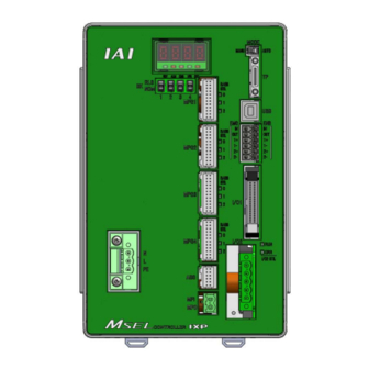
IAI MSEL Program Controller Manuals
Manuals and User Guides for IAI MSEL Program Controller. We have
1
IAI MSEL Program Controller manual available for free PDF download: Instruction Manual
IAI MSEL Instruction Manual (234 pages)
Brand:
IAI
| Category:
Controller
| Size: 7 MB
Table of Contents
Table of Contents
5
Safety Guide ꞏꞏꞏꞏꞏꞏꞏꞏꞏꞏꞏꞏꞏꞏꞏꞏꞏꞏꞏꞏꞏꞏꞏꞏꞏꞏꞏꞏꞏꞏꞏꞏꞏꞏꞏꞏꞏꞏꞏꞏꞏꞏꞏꞏꞏꞏꞏꞏꞏꞏꞏꞏꞏꞏꞏꞏꞏꞏꞏꞏꞏꞏꞏꞏꞏꞏꞏꞏꞏꞏꞏꞏꞏꞏꞏꞏꞏꞏꞏꞏꞏꞏꞏꞏꞏꞏꞏꞏꞏꞏꞏꞏꞏꞏꞏꞏꞏꞏ1
9
Controller Model Codes and Applicable Actuators ꞏꞏꞏꞏꞏꞏꞏꞏꞏꞏꞏꞏꞏꞏꞏꞏꞏꞏꞏꞏꞏꞏꞏꞏꞏꞏꞏꞏꞏꞏꞏꞏꞏꞏꞏꞏꞏꞏꞏꞏꞏꞏꞏꞏꞏꞏꞏꞏꞏꞏ8
16
Precautions in Operation ꞏꞏꞏꞏꞏꞏꞏꞏꞏꞏꞏꞏꞏꞏꞏꞏꞏꞏꞏꞏꞏꞏꞏꞏꞏꞏꞏꞏꞏꞏꞏꞏꞏꞏꞏꞏꞏꞏꞏꞏꞏꞏꞏꞏꞏꞏꞏꞏꞏꞏꞏꞏꞏꞏꞏꞏꞏꞏꞏꞏꞏꞏꞏꞏꞏꞏꞏꞏꞏꞏꞏꞏꞏꞏꞏꞏꞏꞏꞏꞏꞏꞏ9
17
International Standards Compliances
20
Name for each Parts and Their Functions
21
Actuator Axes
25
Chapter 1 Specifications Check
31
Product Check
31
Parts (Excluding Options)
31
Teaching Tool (Optional)
31
Instruction Manuals Related to this Product, Which Are Contained in the Instruction Manual (DVD)
32
How to Read the Model Plate
32
How to Read the Model
32
Basic Specifications
35
Selection of the Circuit Breaker
36
Selection of the Leakage Breaker
36
External Dimensions
37
Interfaces
38
Standard I/O
38
Extension I/O
39
Absolute Battery Box (to be Connected for Simple Absolute Type)
40
Installation and Storage Environment
41
Noise Prevention and the Installation
42
Chapter 2 Wiring
45
Wiring (Example Connection of Devices) Diagram
45
Circuit Diagram (Example)
47
Power Supply Circuit
47
Emergency Stop and Enable Circuit (PC/PCF/PCX Type)
48
Emergency Stop and Enable Circuit (PG/PGF/PGX Type)
50
Motor Encoder Circuit
52
PIO Circuit
54
Connection to Absolute Battery Box
61
Absolute
61
Wiring Method
62
Connection to AC Power Input Connector
62
Wiring the Emergency Stop Circuit (System I/O)
63
Wiring for Actuator
64
Wiring for Motor Driving Power Line Connector
65
Wiring to Single Absolute Battery Unit
65
Wiring for PIO
66
Wiring for the Teaching Tool (SIO Connector, USB Connector)
67
Chapter 3 Operation
69
Types of Operations
69
Receiving and Forwarding of I/O Signals Necessary for Operation
70
Starting the Controller
73
Turning on the Power and Cutoff
73
Panel Window Display
74
Status LED
76
Position Table and Program Creation and Writing
78
Program Operation
79
Auto Start Upon Power on
79
Starting a Program by Specifying Its Program Number
81
7-Segment Display SEL Program
82
Chapter 4 Home-Return / Absolute Reset
85
Home-Return Preparation (Incremental Type)
85
Absolute Reset Preparation
86
SCARA Robot)
86
Absolute Reset for SCARA Robot (Battery-Less Absolute Type)
89
Absolute Reset Preparation
90
Simple Absolute Type (PC/PG/PCF/PGF Type Dedicated)
98
Status LED
98
Absolute Reset Preparation
98
Simple Absolute Type
99
Absolute Encoder Backup Type
100
Charging Absolute Battery
100
Detection of Absolute Battery Voltage Drop
101
Chapter 5 I/O Parameter
103
I/O Parameters
105
All Axes Common Parameters
121
Axis-Specific Parameters
127
Driver Card Parameters
135
Encoder Parameters
138
I/O-Slot Card Parameters
139
Other Parameters
143
Parameters for Linear / Rotation Controls
147
Permission of SIO/PIO Program Startup with Password
150
Parameter Setting (Applied)
151
Want to Operate the System Tentatively Without Using I/Os
152
Want to Output an Auto Operation Determination Signal from the Controller
152
Want to Retain Current Output Statuses Even During Emergency Stop
152
Want to Start an Emergency Program
153
Want to Enable Auto Recovery (Restart) Upon Cancellation of Emergency Stop
153
Emergency Stop
153
Want to Enable Auto Recovery (Error Reset) Upon Cancellation of Emergency Stop
154
Emergency Stop
154
Want to Return to the Condition Immediately before Emergency Stop
154
Want to Restart the Controller Externally
154
Want to Turn on the Servo Externally
154
Want to Make a Home-Return on Actuators Externally
155
Want to Execute the Controller Program Externally
155
Want to Execute a Program Externally by Making an Indication of a Program Number in Binary
155
Program Number in Binary
155
Want to Pause Controller Externally During Automatic Operation
155
Want to Reset Errors Externally
156
Want to Change Input Port Assignments
156
Want to Change Output Port Assignments
157
Want to Output that Home-Return (Home Position) Operation Is Complete on All Actuators
157
On All Actuators
157
Want to Output the Error Level
158
Want to Output the Emergency Stop Status
158
Want to Know the Current Operation Mode
158
Chapter 6 Troubleshooting
159
Action to be Taken Upon Occurrence of Problem
159
Error Level Control
160
Error List (MAIN Application)
162
Chapter 7 Appendix
205
Example of Safety Circuit for PG/PGF/PGX Type
205
(Conforming to Safety Category)
205
Stopping Method and Recovery
209
Stopping Method
209
Recovery
210
Extension SIO
211
Specification
211
Functions
211
Wiring
211
Status Display
212
Parameter Settings
212
Cartesian Axis Coordinate Systems
215
Coordinates for Coordinate System Definition Unit
215
Base Coordinate System
216
Work Coordinate System
217
Tool Coordinate System
221
Setting of Parameters
225
Caution Note
227
Chapter 8 Warranty
229
Warranty Period
229
Scope of the Warranty
229
Honoring the Warranty
229
Limited Liability
229
Conditions of Conformance with Applicable Standards/Regulations, Etc., and Applications
230
Other Items Excluded from Warranty
230
Change History
231
Advertisement
Advertisement
Related Products
IAI Msep
iai MCON-CG
iai MCON-C
IAI MSCON
IAI acon
IAI ACON-C
IAI ACON-CA
IAI ACON-CB
IAI ACON-CB series
IAI ACON-CG
IAI Categories
Controller
Digital Camera
Gateway
Industrial Equipment
Security Camera
More IAI Manuals
Login
Sign In
OR
Sign in with Facebook
Sign in with Google
Upload manual
Upload from disk
Upload from URL