
Related Manuals for IAI DeviceNet MSEL Series


Summary of Contents for IAI DeviceNet MSEL Series
- Page 1 Operation Manual Twenty Fourth Edition XSEL MSEL SSEL SCON-C ASEL E-Con PSEL RCS-C...
- Page 3 Information contained in this Operation Manual is subject to change without notice for the purpose of product improvement. If you have any question or comment regarding the content of this manual, please contact the IAI sales office near you. Using or copying all or part of this Operation Manual without permission is prohibited.
- Page 4 [Action] Use a PLC of other type, or use a DeviceNet master unit C200HW-DRM21-V1 or CVM1-DRM21-V1 manufactured in or after October 2008. If changing the PLC is difficult, contact the IAI sales office near you or our customer center “Eight.”...
- Page 5 Caution: The following functions are described in the separate operation manual. Title of operation manual/Overview Control number DeviceNet Operation Manual Refer to this operation manual if you are using an ME0256 ACON, DCON, PCON or SCON (excluding SCON-C) controller(s).
-
Page 6: Table Of Contents
Table of Contents Safety Guide..........................1 Overview ..........................9 XSEL-J/K/P/Q/JX/KX/PX/QX ....................10 Models ..........................10 (1) Compact type (J type) ....................11 (2) General-purpose type (K type)..................11 (3) P/Q types........................12 Interface Specifications...................... 13 DeviceNet board ........................ 14 2.3.1 Name of Each Part..................... - Page 7 MSEL ··············································································································· 4.1 Model ··········································································································· 4.2 Interface Specifications......................56 4.3 DeviceNet Interface························································································· (1) Communication Connector········································································ (2) Monitor LED indications ··········································································· 4.4 Parameter Settings ·························································································· 4.5 Setting Example ····························································································· (1) Example for when using only DeviceNet (I/O2) ·············································· (2) Example for when using DeviceNet and I/O Board 1 together ···························...
- Page 8 Interface Specifications.....................100 DeviceNet Interface ......................101 7.3.1 Name of Each Part....................101 7.3.2 DIP Switch Settings....................102 (1) Setting the node address (MAC ID) ................102 (2) Setting the baud rate....................102 7.3.3 Monitor LED Indicators....................103 Input/Output (I/O) ......................104 (1) RCS-C signal assignments ..................104 (2) E-Con signal assignments ..................105 SCON-C ..........................107 Model ..........................107 Interface Specifications......................108...
-
Page 9: Safety Guide
Safety Guide “Safety Guide” has been written to use the machine safely and so prevent personal injury or property damage beforehand. Make sure to read it before the operation of this product. Safety Precautions for Our Products The common safety precautions for the use of any of our robots in each operation. Operation Description Description... - Page 10 Operation Description Description Transportation ● When carrying a heavy object, do the work with two or more persons or utilize equipment such as crane. ● When the work is carried out with 2 or more persons, make it clear who is to be the leader and who to be the follower(s) and communicate well with each other to ensure the safety of the workers.
- Page 11 Operation Description Description Installation (2) Cable Wiring and Start ● Use our company’s genuine cables for connecting between the actuator and controller, and for the teaching tool. ● Do not scratch on the cable. Do not bend it forcibly. Do not pull it. Do not coil it around.
- Page 12 Operation Description Description Installation (4) Safety Measures and Start ● When the work is carried out with 2 or more persons, make it clear who is to be the leader and who to be the follower(s) and communicate well with each other to ensure the safety of the workers.
- Page 13 Operation Description Description Trial Operation ● When the work is carried out with 2 or more persons, make it clear who is to be the leader and who to be the follower(s) and communicate well with each other to ensure the safety of the workers. ●...
- Page 14 Operation Description Description Maintenance ● When the work is carried out with 2 or more persons, make it clear who is and Inspection to be the leader and who to be the follower(s) and communicate well with each other to ensure the safety of the workers. ●...
- Page 15 Alert Indication The safety precautions are divided into “Danger”, “Warning”, “Caution” and “Notice” according to the warning level, as follows, and described in the Operation Manual for each model. Level Degree of Danger and Damage Symbol This indicates an imminently hazardous situation which, if the Danger Danger product is not handled correctly, will result in death or serious injury.
-
Page 17: Overview
Overview DeviceNet, which is an open field network, is a multiple-bit type multi-vendor network that combines controls and data on a machine/line control level. By connecting to DeviceNet, XSEL, TT, TTA, MSEL, ASEL, PSEL, SSEL, ACON, DCON, PCON, SCON, RCS-C and E-Con controllers (hereinafter referred to collectively as “controllers” or individually as a “controller”... -
Page 18: Xsel-J/K/P/Q/Jx/Kx/Px/Qx
XSEL-J/K/P/Q/JX/KX/PX/QX 2.1 Models DeviceNet-ready XSEL controllers come in six different models as specified below. Installation position of DeviceNet board Network I/O Board installation position Controller points I/O slot Standard Expansion Expansion Expansion XSEL model type (maximum arrangement slot slot 1 slot 2 slot 3 inputs/outputs) -
Page 19: Compact Type (J Type)
(1) Compact type (J type) 1 axis 2 axes 3/4 axes DeviceNet board DeviceNet board DeviceNet board (Note) I/O boards cannot be installed in controllers of 1/2-axis specifications. Only one (Note 1) expansion I/O board can be installed in controllers of 3/4-axis specifications. Fig. -
Page 20: P/Q Types
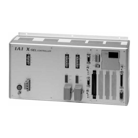
(3) P/Q types A DeviceNet board is installed in the installation position of field network board. DeviceNet board Standard I/O DeviceNet board Expansion I/O Standard I/O XSEL-P-1--DV----3 XSEL-Q-1--DV----3 XSEL-P-2---DV----3 XSEL-Q-2---DV----3 XSEL-P-3----DV----3 XSEL-Q-3----DV----3 XSEL-P-4-----DV----3 XSEL-Q-4-----DV----3 XSEL-Q-5------DV----3 XSEL-P-5------DV----3 XSEL-Q-6-------DV----3 XSEL-P-6-------DV----3 Fig. 2-3 (Note 1) Expansion I/O board Model [1] IA-103-X-32 (32 input points/16 output points, NPN specification) -
Page 21: Interface Specifications
2.2 Interface Specifications The DeviceNet interface specifications are summarized below. c i f Communication protocol A certified DeviceNet 2.0 interface module is used (certification pending). Group 2 only server Network-powered insulation node Communication specification Master-slave connection Bit strobe Polling Cyclic Baud rate 500 k / 250 k / 125 kbps (selectable by DIP switches) Communication cable length... -
Page 22: Devicenet Board
2.3 DeviceNet board 2.3.1 Name of Each Part J/K/JX/KX P/Q/PX/QX types types DeviceNet communication connector Monitor LEDs DIP switches • Node address setting • Baud rate setting DIP switches • Node address setting • Baud rate setting Monitor LEDs DeviceNet communication connector... -
Page 23: Dip Switch Settings
2.3.2 DIP Switch Settings The DIP switches are used to set the following items: (1) Node address (2) Baud rate (Note) Turn off the controller power before setting the DIP switches. (1) Setting the node address (MAC ID) Set the node address (MAC ID) using a hexadecimal value according to the table below. 1: ON 0: OFF c t i Node address... -
Page 24: Monitor Led Indicators
2.3.3 Monitor LED Indicators The two LEDs, MS and NS, provided on the front panel of the board are used to check the board (node) condition and network condition. (The remaining two LEDs are not currently used.) The LEDs illuminate in two colors (red and green), and you can monitor the conditions listed in the table below based on the illumination status and color of each LED. -
Page 25: Setting Of I/O Parameters (Assignment Of I/O Ports)
2.4 Setting of I/O Parameters (Assignment of I/O Ports) Set the XSEL I/O ports to be used in DeviceNet communication. XSEL controllers support various I/O port settings through use of I/O parameters. (For details, refer to the “Operation Manual for XSEL Controller.”) A representative method to set I/O parameters is explained below. -
Page 26: Factory-Set Parameters
2.4.2 Factory-set Parameters (1) Factory-set parameters for J/K types Parameter name Input range Setting Remarks I/O port assignment type 0 ~ 20 0: Fixed assignment 1: Automatic assignment (Priority: Assigned from slot 1) * Ports are assigned consecutively only for slots where a board is physically installed, starting from slot 1, for safety reasons. -
Page 27: Factory-Set Parameters For P/Q Types
(2) Factory-set parameters for P/Q types Parameter name Input range Setting Remarks I/O port assignment type 0 ~ 20 0: Fixed assignment 1: Automatic assignment (Priority: Assigned from slot 1) * Ports are assigned consecutively only for slots where a board is physically installed, starting from slot 1, for safety reasons. -
Page 28: P/Q Types
(3) P/Q types Standard Standard Expansion I/O Parameter Parameter Parameter Parameter Parameter Parameter Parameter... -
Page 29: Parameter Setting Examples
2.5 Parameter Setting Examples 2.5.1 Setting Example for J/K Types (1) Setting example when only a DeviceNet board is installed Assign 32 input points and 16 output points to the DeviceNet board from the first standard I/O port, as you would for the standard XSEL I/O board (50-pin connector), and do not use any other I/O port. - Page 30 I/O parameters for XSEL J/K types Input Default value Parameter name Setting Remarks (reference) range I/O port assignment type 0 ~ 20 0: Fixed assignment 1: Automatic assignment (Priority: Assigned from slot 1) * Ports are assigned consecutively only for slots where a board is physically installed, starting from slot 1, for safety reasons.
-
Page 31: Setting Example When A Devicenet Board Is Used Together With An Expansion I/O Board
(2) Setting example when a DeviceNet board is used together with an expansion I/O board a. Assign 256 input points and 256 output points to the DeviceNet board from the first standard I/O port, and assign the subsequent I/O port numbers to the expansion I/O board IA-103-X-32 (32 input points, 16 output points). - Page 32 I/O parameters for XSEL J/K types Input Default value Parameter name Setting Remarks (reference) range I/O port assignment type 0 ~ 20 0: Fixed assignment 1: Automatic assignment (Priority: Assigned from slot 1) * Ports are assigned consecutively only for slots where a board is physically installed, starting from slot 1, for safety reasons.
- Page 33 b. Use the expansion I/O board IA-103-X-32 (32 input points, 16 output points) for standard I/O ports, and assign 256 input points and 256 output points to the DeviceNet board as general-purpose I/O ports. The same settings apply to J-type controllers. Input port Nos.
- Page 34 I/O parameters for XSEL J/K types Input Default value Parameter name Setting Remarks (reference) range I/O port assignment type 0 ~ 20 0: Fixed assignment 1: Automatic assignment (Priority: Assigned from slot 1) * Ports are assigned consecutively only for slots where a board is physically installed, starting from slot 1, for safety reasons.
-
Page 35: Setting Example For P/Q Types
2.5.2 Setting Example for P/Q Types (1) Setting example when only a DeviceNet board is installed Assign 32 input points and 16 output points to the DeviceNet board from the first standard I/O port, as you would for the standard XSEL I/O board (50-pin connector), and do not use any other I/O port. Not used. - Page 36 I/O parameters for XSEL P/Q types Input Default value Parameter name Setting Remarks (reference) range I/O port assignment type 0 ~ 20 0: Fixed assignment 1: Automatic assignment (Priority: Assigned from slot 1) * Ports are assigned consecutively only for slots where a board is physically installed, starting from slot 1, for safety reasons.
- Page 37 Input Default value Parameter name Setting Remarks (reference) range Network attribute 2 C80000H Bits 16 to 27: 0H ~ Optional FFFFFFFFH Value of Link Timeout at initializing of the Fieldbus (100ms) (XSEL-P/Q: Main application of Ver.1.28 or later XSEL-PX/QX: Main application of Ver.0.60 or later) (Example) The initial value C80000H is bit 16 to 27= C8H = 200 (in 100ms unit) 200 ×...
-
Page 38: Setting Example When A Devicenet Board Is Used Together With A Standard I/O Board
(2) Setting example when a DeviceNet board is used together with a standard I/O board a. Assign 256 input points and 256 output points to the DeviceNet board from the first standard I/O port, and assign the subsequent I/O port numbers to the standard I/O board. Input port Nos. - Page 39 I/O parameters for XSEL P/Q types Input Default value Parameter name Setting Remarks (reference) range I/O port assignment type 0 ~ 20 0: Fixed assignment 1: Automatic assignment (Priority: Assigned from slot 1) * Ports are assigned consecutively only for slots where a board is physically installed, starting from slot 1, for safety reasons.
- Page 40 Input Default value Parameter name Setting Remarks (reference) range Network attribute 2 C80000H Bits 16 to 27: 0H ~ Optional FFFFFFFFH Value of Link Timeout at initializing of the Fieldbus (100ms) (XSEL-P/Q: Main application of Ver.1.28 or later XSEL-PX/QX: Main application of Ver.0.60 or later) (Example) The initial value C80000H is bit 16 to 27= C8H = 200 (in 100ms unit) 200 ×...
- Page 41 b. Use the standard I/O board IA-103-X-32 (32 input points, 16 output points) for standard I/O ports, and assign 256 input points and 256 output points to the DeviceNet board as general-purpose I/O ports. The same settings apply to J-type controllers. Input port Nos.
- Page 42 I/O parameters for XSEL P/Q types Input Default value Parameter name Setting Remarks (reference) range I/O port assignment type 0 ~ 20 0: Fixed assignment 1: Automatic assignment (Priority: Assigned from slot 1) * Ports are assigned consecutively only for slots where a board is physically installed, starting from slot 1, for safety reasons.
- Page 43 Input Default value Parameter name Setting Remarks (reference) range Network attribute 2 C80000H Bits 16 to 27: 0H ~ Optional FFFFFFFFH Value of Link Timeout at initializing of the Fieldbus (100ms) (XSEL-P/Q: Main application of Ver.1.28 or later XSEL-PX/QX: Main application of Ver.0.60 or later) (Example) The initial value C80000H is bit 16 to 27= C8H = 200 (in 100ms unit) 200 ×...
-
Page 44: I/O Port Numbers For Xsel
2.6 I/O Port Numbers for XSEL The table below lists the standard I/O port numbers for XSEL controllers. On XSEL controllers, port numbers and function assignments can be changed using I/O parameters. (For details, refer to the “Operation Manual for XSEL Controller.”) Port No. - Page 45 Reference Port numbers are assigned to bit addresses in the PLC in units of 16 points, starting from the channel corresponding to the node address set with the DIP switches. (This does not apply if a configurator is used to assign port numbers.) XSEL (Input) (Output)
-
Page 46: Xsel-R(A)/S(A)/R(A)X/S(A)X/R(A)Xd/S(A)Xd
2.6 I/O Port Numbers for X-SEL XSEL-R(A)/S(A)/R(A)X/S(A)X/R(A)XD/S(A)XD The table below lists the standard I/O port numbers for X-SEL controllers. The I/O data is handled as either bit data or word data. The I/O data is mapped to input and output ports. On X-SEL controllers, port numbers and function assignments can be changed using I/O parameters. -
Page 47: Interface Specifications
Reference 3.2 Interface Specifications Port numbers are assigned to bit addresses in the PLC in units of 16 points, starting from the Item Specification channel corresponding to the node address set with the DIP switches. Communication DeviceNet 2.0 (This does not apply if a configurator is used to assign port numbers.) protocol Group 2 only server Network-powered insulation node... -
Page 48: Devicenet Interface
2.6 I/O Port Numbers for X-SEL DeviceNet Interface (1) Name of Each Part The table below lists the standard I/O port numbers for X-SEL controllers. On X-SEL controllers, port numbers and function assignments can be changed using I/O parameters. (For details, refer to the “Operation Manual for X-SEL Controller.”) Monitor LEDs Pin Color... -
Page 49: Parameter Settings
Reference Parameter Settings Port numbers are assigned to bit addresses in the PLC in units of 16 points, starting from the Set to the I/O parameters in the controller by using a teaching tool. channel corresponding to the node address set with the DIP switches. Place the controller's AUTO/MANU switch in the MANU position. - Page 50 2.6 I/O Port Numbers for X-SEL [1] Network Setting Check • For XSEL-R/S Series The table below lists the standard I/O port numbers for X-SEL controllers. Confirm that the 2nd digit of I/O Parameter No.225 Network I/F Module Control setting is showing “2” On X-SEL controllers, port numbers and function assignments can be changed using I/O parameters. (For (DeviceNet).
- Page 51 Reference [3] DeviceNet Board Use Setting Set “1” (Monitoring: use DeviceNet board) to I/O Parameter No.235. Port numbers are assigned to bit addresses in the PLC in units of 16 points, starting from the channel corresponding to the node address set with the DIP switches. Default (This does not apply if a configurator is used to assign port numbers.) Parameter name Input Range Unit...
- Page 52 2.6 I/O Port Numbers for X-SEL [7] I/O Port Top Number Setting Set the top port number of the port range used in I/O Parameters No. 233 to 234. The table below lists the standard I/O port numbers for X-SEL controllers. Note The port numbers assigned here are the starting input and output port numbers.The max I/O port will be On X-SEL controllers, port numbers and function assignments can be changed using I/O parameters.
-
Page 53: Setting Example
Reference Setting Example Port numbers are assigned to bit addresses in the PLC in units of 16 points, starting from the (1) Example for when using only DeviceNet channel corresponding to the node address set with the DIP switches. (This does not apply if a configurator is used to assign port numbers.) It is how to establish the setting when using DeviceNet to 16 points of each input and output from the top of the standard I/O ports, and no other I/O port (for I/O board, etc.) is to be used. - Page 54 2.6 I/O Port Numbers for X-SEL Default Parameter name Input Range Unit Remarks (Reference) The table below lists the standard I/O port numbers for X-SEL controllers. 0:No Monitoring (Not to use I/O board) On X-SEL controllers, port numbers and function assignments can be changed using I/O parameters. (For 1:Monitoring details, refer to the “Operation Manual for X-SEL Controller.”) Standard I/O Error Monitoring...
-
Page 55: Example For When Using Devicenet And I/O Board 1 Together
Reference (2) Example for when using DeviceNet and I/O Board 1 together It is how to establish the setting when using DeviceNet to 256 points of each input and output from the top Port numbers are assigned to bit addresses in the PLC in units of 16 points, starting from the of the extended I/O ports and assigning the I/O board (48 points for each input and output) to the standard channel corresponding to the node address set with the DIP switches. - Page 56 2.6 I/O Port Numbers for X-SEL Default Parameter name Input Range Unit Remarks (Reference) The table below lists the standard I/O port numbers for X-SEL controllers. 0:No Monitoring (Not to use I/O board) On X-SEL controllers, port numbers and function assignments can be changed using I/O parameters. (For 1:Monitoring details, refer to the “Operation Manual for X-SEL Controller.”) Standard I/O Error Monitoring...
-
Page 57: Example For When Using Devicenet And I/O Board 1 Together
Reference (3) Example for when using DeviceNet and I/O Board 1 together It is how to establish the setting when using DeviceNet to 192 points of each input and output from the top Port numbers are assigned to bit addresses in the PLC in units of 16 points, starting from the of the extended I/O ports and assigning the I/O board (48 points for each input and output) to the standard channel corresponding to the node address set with the DIP switches. - Page 58 2.6 I/O Port Numbers for X-SEL Default Parameter name Input Range Unit Remarks (Reference) The table below lists the standard I/O port numbers for X-SEL controllers. 0:No Monitoring (Not to use I/O board) On X-SEL controllers, port numbers and function assignments can be changed using I/O parameters. (For 1:Monitoring details, refer to the “Operation Manual for X-SEL Controller.”) Standard I/O Error Monitoring...
-
Page 59: Standard I/O Ports Of Xsel Controller
Reference Standard I/O Ports of XSEL Controller Port numbers are assigned to bit addresses in the PLC in units of 16 points, starting from the For the standard I/O ports of XSEL controller, it is possible to change the specified functions except for the channel corresponding to the node address set with the DIP switches. general-purposed I/O with the I/O parameters. [Refer to the instruction manual for the XSEL-R/S/RX/SX/ (This does not apply if a configurator is used to assign port numbers.) RXD/SXD controller or XSEL-RA/SA/RAX/SAX/RAXD/SAXD controller for more information.] • Settings of Standard I/O Ports at Delivery... - Page 60 2.6 I/O Port Numbers for X-SEL Reference The table below lists the standard I/O port numbers for X-SEL controllers. When bit addresses are set in the PLC, port numbers are assigned in units of 16 points, On X-SEL controllers, port numbers and function assignments can be changed using I/O parameters. (For starting from the channels corresponding to the node address set by the parameters.
-
Page 61: Troubleshooting
Reference Troubleshooting Port numbers are assigned to bit addresses in the PLC in units of 16 points, starting from the 1) In case it is not possible to connect the network, check the current condition on the display of channel corresponding to the node address set with the DIP switches. monitoring LEDs of DeviceNet Board. - Page 62 2.6 I/O Port Numbers for X-SEL Error name Contents and Treatment A communication board error was detected. The table below lists the standard I/O port numbers for X-SEL controllers. Reboot the XSEL controller. If the same error occurs again, please D77 Fieldbus error (Exception) contact us.
-
Page 63: Msel
4. MSEL MSEL, which are applicable for DeviceNet, deal the I/O data as the bit data or word data, and operate while reflecting the data. 4.1 Model The model codes are as shown below: • MSEL-PC(F)-□-□-□-□-DV • MSEL-PCX-□-□-□-□-DV • MSEL-PG(F)-□-□-□-□-DV •... -
Page 64: Interface Specifications
4.2 Interface Specifications Item Specification Communication protocol DeviceNet 2.0 Group 2 only server Network-powered insulation node Communication specification Master Slave connection Bit strobe Polling Cyclic/Change of State Baud rate 500k/250k/125kbps (Software setting by I/O parameter) Communication cable length Communication Network Max. length Maximum Total speed... -
Page 65: Devicenet Interface
DeviceNet Interface (1) Communication Connector Details Pin color White Black Negative side of communication power line None Blue Low side of signals None Shield Blue White High side of signals Black Positive side of communication power line (2) Monitor LED indications The board operation status and network condition are obtained with the two LEDs located in the front of the communication board. -
Page 66: Parameter Settings
Parameter Settings Set to the I/O parameters in the controller by using a teaching tool. Set the mode switchover switch on the front panel to MANU side. The teaching tool version applicable for MSEL is as shown below: • XSEL PC software : V10.00.09.00 to •... - Page 67 [4] Communication Speed Setting Have the baud rate set in I/O Parameter No. 227. Match the setting to the communication speed of the master unit. Default Parameter name Input Range Unit Remarks (Reference) 0: 125Kbps 227 I/O2 Fieldbus Baud Rate 0 to 2 1: 250Kbps 2: 500Kbps...
- Page 68 [8] Data Retaining Setting at DeviceNet Communication Error Have the setting established in I/O Parameter No. 120 whether to clear the input port data at 0 or to remain the data when a communication error is occurred. Default Parameter name Input Range Unit Remarks...
-
Page 69: Setting Example
Setting Example (1) Example for when using only DeviceNet (I/O2) It is how to establish the setting when using DeviceNet (I/O2) to 16 ports of each input and output from the top of the standard I/O ports, and no other I/O port (for I/O board, etc.) is to be used. Not Applicable (I/O board) Input Port No.48 to 63 Output Port No.348 to 363... - Page 70 Default Parameter name Input Range Unit Remarks (Reference) Bits 0-3(First digit): I/O2 module type 0: Not Mounted 225 Extension I/O Control (Confirmation) 1:CC-Link 2:DeviceNet 3:PROFIBUS DeviceNet node address range: 226 I/O2 Fieldbus Node Address 0 to 63 Optional 0 to 63 Follow 0: 125Kbps 227 I/O2 Fieldbus Baud Rate...
-
Page 71: Example For When Using Devicenet And I/O Board 1 Together
(2) Example for when using DeviceNet and I/O Board 1 together This is a setting to use I/O board (16 points each for input and output) and DeviceNet on I/O port (I/O2) at 240 points of ports each for input and output on the ports. Input Port No.16 to 31 Output Port No.316 to 331 (I/O board (I/O1)) - Page 72 Default Parameter name Input Range Unit Remarks (Reference) Bits 0-3(First digit): I/O2 module type 0: Not Mounted Extension I/O Control (Confirmation) 1:CC-Link 2:DeviceNet 3:PROFIBUS DeviceNet node address range: I/O2 Fieldbus Node Address 0 to 63 Optional 0 to 63 Follow 0: 125Kbps I/O2 Fieldbus Baud Rate 0 to 2...
-
Page 73: I/O Ports Of The Msel
I/O Ports of the MSEL It is available to add special functions beside the general-purposed input and output in the I/O ports. [Refer to MSEL Controller Operation Manual 2.2.5 PIO Circuit, Chapter 5 Parameter for the details.] ● I/O Port Setting at Delivery Port No. - Page 74 Port No. Function Port No. Function Program start Alarm output READY output Emergency-stop output General-purpose input Program number specification (BCD:1 / BIN:1) Program number specification External External (BCD:2 / BIN:2) Program number specification (Device (Device (BCD:4 / BIN:4) General-purpose output Net) Net) Program number specification...
- Page 75 Reference When bit addresses are set in the parameter, port numbers are assigned in units of 16 points, starting from the channels corresponding to the node address set by the DIP switches. (This does not apply when a configurator is used.) (Input) (Output) MSEL...
-
Page 76: Troubleshooting
Troubleshooting 1) In case it is not possible to connect the network, check the current condition on the display of monitoring LEDs of DeviceNet Board. [Refer to Section 4.2] Check the settings of the MSEL and the settings of the master unit referring to the instruction manuals of the master unit. - Page 77 Error name Contents and Treatment I/O assignment is duplicated. Check to see that a number out of the I/O port number (except for -1) is not set to I/O Parameters No. 2 to 9, a number out of indication is I/O Duplication Assignment Error not input to I/O port start number, or a number out of indication is not input to I/O Parameters No.
-
Page 78: Tabletop Robot Tta
5. Tabletop Robot TTA Tabletop Robot TTA, which are applicable for DeviceNet, deal the I/O data as the bit data or word data, and operate while reflecting the data. 5.1 Model The model codes are as shown below: • TTA-A□(SL/SH) (G)-WA-□-□-□-□-DV •... -
Page 79: Interface Specifications
5.2 Interface Specifications Item Specification Communication protocol DeviceNet 2.0 Group 2 only server Network-powered insulation node Communication specification Master Slave connection Bit strobe Polling Cyclic/Change of State Baud rate 500k/250k/125kbps (Software setting by I/O parameter) Communication cable length Communication Network Max. length Maximum Total speed... -
Page 80: Devicenet Interface
5.3 DeviceNet Interface Two pieces of DeviceNet board can be mounted at the maximum. (1) Name of Each Part DeviceNet communication Monitor LED (I/O2) connector (I/O2) Monitor LED (I/O3) DeviceNet communication connector (I/O3) Details Pin color Black Negative side of communication power line Blue Low side of signals None... -
Page 81: Parameter Settings
Parameter Settings Set to the I/O parameters in the controller by using a teaching tool. Note The setting parameter number will differ depending on the slot number (I/O2 or I/O3) mounting DeviceNet. Check on which slot the DeviceNet board is mounted in your TTA before starting the setting work. Set the mode switchover switch on the front panel to MANU side. - Page 82 Network Setting Check Confirm that the I/O Parameter No. 225 Network I/F Module Control setting is showing “2” (DeviceNet). (The setting of this parameter is to be established before delivery) Note The digit to check will differ depending on the position to mount DeviceNet (Mounted on I/O2: 1 digit, mounted on I/O3: 2 digit) Parameter name...
- Page 83 [4] Communication Speed Setting Have the baud rate set in I/O Parameter No. 227 and 238 in accordance with the position to mount DeviceNet board. Match the setting to the communication speed of the master unit. Default Parameter name Input Range Unit Remarks (Reference)
- Page 84 [6] I/O Port Top Number Setting Have the top port number in the port range to be used set in I/O Parameter No. 16, 17, 233 and 234 in accordance with the position to mount DeviceNet board. Note The values entered into these parameters must be evenly divisible by 8. Default Parameter name Input Range...
-
Page 85: Setting Example
Setting Example (1) Example for when using only DeviceNet (I/O2) It is how to establish the setting when using DeviceNet (I/O2) to 16 ports of each input and output from the top of the standard I/O ports, and no other I/O port (for I/O board, etc.) is to be used. Input Port No.48 to 63 Not Applicable (I/O board) Output Port No.348 to 363... - Page 86 Default Parameter name Input Range Unit Remarks (Reference) Bits 8 to 11: Input port data selected at I/O3 Fieldbus link error 0 to 0: Input port data clear 121 Network Attribute 2 C80000 Optional FFFFFFFF 1: Input port data retained Bits 16 to 27: Value of Link Timeout at initializing of the Fieldbus (100ms)
-
Page 87: Example For When Using Devicenet And I/O Board 1 Together
(2) Example for when using DeviceNet and I/O Board 1 together This is a setting to use I/O board (16 points each for input and output) and DeviceNet on I/O port (I/O2) at 240 points of ports each for input and output on the ports. Extended Input Ports No.48 to 271 Standard Input Port No.16 to 31 Extended Output Ports No.348 to 571... - Page 88 Default Parameter name Input Range Unit Remarks (Reference) Bits 8 to 11: Input port data selected at I/O3 Fieldbus link error 0 to 0: Input port data clear Network Attribute 2 C80000 Optional FFFFFFFF 1: Input port data retained Bits 16 to 27: Value of Link Timeout at initializing of the Fieldbus (100ms) Bits 0-3(First digit):...
-
Page 89: Example For When Using Devicenet (I/O2 And I/O3) Together
(3) Example for when using DeviceNet (I/O2 and I/O3) together This is a setting to mount two pieces of DeviceNet and use 120 points on each port. Extended Input Ports No.48 to 167 Standard Input Port No.168 to 287 Extended Output Ports No.348 to 467 Standard Output Port No.468 to 587 (DeviceNet board (I/O2)) (DeviceNet board (I/O3)) - Page 90 Default Parameter name Input Range Unit Remarks (Reference) Bits 8 to 11: Input port data selected at I/O3 Fieldbus link error 0 to 0: Input port data clear 121 Network Attribute 2 C80000 Optional FFFFFFFF 1: Input port data retained Bits 16 to 27: Value of Link Timeout at initializing of the Fieldbus (100ms)
-
Page 91: I/O Ports Of The Tta
I/O Ports of the TTA It is available to add special functions beside the general-purposed input and output in the I/O ports. [Refer to TTA Controller Operation Manual 4.6 How to Use Internal DIO, Chapter 5 Parameter for the details.] ●... - Page 92 Port No. Function Port No. Function General-purpose input Alarm output (Software reset) Ready output (Servo ON) Emergency stop output (Auto program start) (Software interlock) (Pause reset) (Pause) External External General-purpose output (Device (Device Net) Net) General-purpose input (Home return) General-purpose output General-purpose input In this table, shows the settings when DeviceNet Connection Board is installed in “I/O2”.
-
Page 94: Troubleshooting
Troubleshooting 1) In case it is not possible to connect the network, check the current condition on the display of monitoring LEDs of DeviceNet Board. [Refer to Section 5.2] Check the settings of the TTA and the settings of the master unit referring to the instruction manuals of the master unit. - Page 95 Error name Contents and Treatment It is a parameter setting error. Check to see that a number out of the I/O port number (except for -1) is not set to I/O Parameters No. 2 to 9, a I/O Assignment Parameter Error number out of indication is not input to I/O port start number, or a number out of indication is not input to I/O Parameters No.
-
Page 96: Tabletop Robot Tt
Tabletop Robot TT 3.1 Model Model: TT--I--PV Maximum numbers of network I/O points: 240/240 Standard I/O A DeviceNet board is installed in the installation position of field network board. -
Page 97: Interface Specifications
3.2 Interface Specifications The DeviceNet interface specifications are summarized below. Item Specification Communication protocol A certified DeviceNet 2.0 interface module is used (certification pending). Group 2 only server Network-powered insulation node Communication specification Master-slave connection Bit strobe Polling Cyclic Baud rate 500 k / 250 k / 125 kbps (selectable by DIP switches) Communication cable length Baud rate... -
Page 98: Devicenet Board
3.3 DeviceNet board 3.3.1 Name of Each Part 6.3.1 TT type Monitor LEDs DeviceNet communication DIP switches connector • Node address setting • Baud rate setting... -
Page 99: Dip Switch Settings
3.3.2 DIP Switch Settings 6.3.2 The DIP switches are used to set the following items: (1) Node address (2) Baud rate (Note) Turn off the controller power before setting the DIP switches. (1) Setting the node address (MAC ID) Set the node address (MAC ID) using a hexadecimal value according to the table below. 1: ON 0: OFF c t i Node address... -
Page 100: Monitor Led Indicators
3.3.3 Monitor LED Indicators 6.3.3 The two LEDs, MS and NS, provided on the front panel of the board are used to check the board (node) condition and network condition. (The remaining two LEDs are not currently used.) The LEDs illuminate in two colors (red and green), and you can monitor the conditions listed in the table below based on the illumination status and color of each LED. -
Page 101: Setting Of I/O Parameters (Assignment Of I/O Ports)
3.4 Setting of I/O Parameters (Assignment of I/O Ports) Set the TT I/O ports to be used in DeviceNet communication. (1) Board Installation Position (Slot) and I/O Parameter Numbers Standard I/O DeviceNet Parameter No. 14 No. 15 TT robots are shipped with the input ports and output ports used in DeviceNet communication both set to 64 points. -
Page 102: Factory-Set Parameters For Tt Type
(2) Factory-set parameters for TT type Parameter name Input range Setting Remarks I/O port assignment type Reference 0: Fixed assignment only Input port start number for standard Reference 0 + (multiple of 8) (Invalid, if a value is entered only I/O1 based on fixed assignment with a negative sign.) Output port start number for standard... -
Page 103: Parameter Setting Example For Tabletop Robot Tt
(3) Parameter setting example for tabletop robot TT Assign 240 input points and 240 output points to the DeviceNet as general-purpose I/O ports. On TT robots, the I/O port start numbers are fixed. Input port start No. 48 Output port start No. 348 Port are assigned in units of 16 points. - Page 104 I/O parameters for TT type Default Input Parameter name Setting Remarks value range I/O port assignment type Reference 0: Fixed assignment only Input port start number for standard Reference 0 + (multiple of 8) (Invalid, if a value is only I/O1 based on fixed assignment entered with a negative sign.) Output port start number for standard...
-
Page 105: I/O Port Numbers For Tt Robots
3.5 I/O Port Numbers for TT Robots The table below lists the I/O port numbers for TT robots. (For details, refer to the “Controller Operation Manual for Tabletop Robot TT.”) Port No. Function Port No. Function Start ALM (front panel LED) (Soft reset) RDY (front panel LED) (Servo on) EMG (front panel LED) (Start via auto start) Auto mode (Soft interlock) - Page 106 Reference Port numbers are assigned to bit addresses in the PLC in units of 16 points, starting from the channel corresponding to the node address set with the DIP switches. (This does not apply if a configurator is used to assign port numbers.) (Input) (Output) (Input)
-
Page 107: Rcs-C And E-Con
RCS-C and E-Con 4.1 Model DeviceNet-ready RCS-C and E-Con controllers are shown below. (1) RCS-C Model: RCS-C--DV-- Number of I/O points: 8 dedicated input points, 10 dedicated output points 24-V type 100-V/200-V types (2) E-Con Model: ECON---DV-- Number of I/O points: 10 dedicated input points, 12 dedicated output points... -
Page 108: Interface Specifications
4.2 Interface Specifications Item Specification Communication protocol DeviceNet 2.0 (*1) Group 2 only server Network-powered insulation node Support connection Master-slave connection Bit strobe Polling Baud rate 500 k / 250 k / 125 kbps (selectable by DIP switches) Communication cable length Baud rate Maximum network length Maximum branch Total branch... -
Page 109: Devicenet Interface
4.3 DeviceNet Interface 7.3.1 4.3.1 Name of Each Part DeviceNet communication connector Monitor LEDs DIP switches • Node address setting • Baud rate setting... -
Page 110: Dip Switch Settings
4.3.2 DIP Switch Settings 7.3.2 The DIP switches are used to set the following items: (1) Node address (2) Baud rate (Note) Turn off the controller power before setting the DIP switches. (1) Setting the node address (MAC ID) Set the node address (MAC ID) using a hexadecimal value according to the table below. 1: ON 0: OFF c t i Node address... -
Page 111: Monitor Led Indicators
7.3.3 4.3.3 Monitor LED Indicators The two LEDs, MS and NS, provided on the front panel of the controller are used to check the interface (node) condition and network condition. The LEDs illuminate in two colors (red and green), and you can monitor the conditions listed in the table below based on the illumination status and color of each LED. -
Page 112: Input/Output (I/O)
4.4 Input/Output (I/O) The I/O specifications of RCS-C and E-Con controllers are as follows: (1) RCS-C: 8 dedicated input points, 10 dedicated output points (2) E-Con: 10 dedicated input points, 12 dedicated output points The details are explained below. For details on each signal, refer to the “Operation Manual for RCS Series ROBO Cylinder Controller, RCS-C Type” or “Operation Manual for E-Con Controller.”) (1) RCS-C signal assignments 8-bit input... -
Page 113: E-Con Signal Assignments
(2) E-Con signal assignments input Input No. Signal name Output No. Signal name Command position 1 Completed position 1 Command position 2 Completed position 2 Command position 4 Completed position 4 Command position 8 Completed position 8 Command position 16 Completed position 16 Command position 32 Completed position 32... - Page 114 Reference Inputs and outputs are assigned to bit addresses in the PLC sequentially from the youngest number, for the channel corresponding to the node address set with the DIP switches. (Input) (Output) Input No. Output No. Node address (NN) CH and (MM) CH as indicated above represent PLC channel addresses corresponding to node address nn.
-
Page 115: Scon-C
SCON-C 5.1 Model A DeviceNet-ready SCON-C controller is shown below. SCON Model: SCON-C--DV-- Number of I/O points: 16 dedicated input points, 16 dedicated output points... -
Page 116: Interface Specifications
5.2 Interface Specifications c i f Communication protocol DeviceNet 2.0 Group 2 only server Network-powered insulation node Support connection Master-slave connection Bit strobe Polling Baud rate 500 k / 250 k / 125 kbps (selectable by DIP switches) Communication cable length Baud rate Maximum network length Maximum branch Total branch... -
Page 117: Devicenet Interface
5.3 DeviceNet Interface 8.3.1 5.3.1 Name of Each Part DeviceNet communication connector Monitor LEDs DIP switches • Node address setting • Baud rate setting... -
Page 118: Dip Switch Settings
5.3.2 DIP Switch Settings 8.3.2 The DIP switches are used to set the following items: (1) Node address (2) Baud rate (Note) Turn off the controller power before setting the DIP switches. (1) Setting the node address (MAC ID) Set the node address (MAC ID) using a hexadecimal value according to the table below. 1: ON 0: OFF c t i Node address... -
Page 119: Monitor Led Indicators
5.3.3 Monitor LED Indicators 8.3.3 The two LEDs, MS and NS, provided on the front panel of the controller are used to check the interface (node) condition and network condition. The LEDs illuminate in two colors (red and green), and you can monitor the conditions listed in the table below based on the illumination status and color of each LED. -
Page 120: Assignment Of I/O Signals
5.4 Assignment of I/O Signals The I/O specifications of SCON controllers are as follows: 16 dedicated input points, 16 dedicated output points The details are explained below. Six I/O patterns are available, from which a desired pattern can be selected using Parameter No. 25 (PIO pattern selection). - Page 121 Setting of Parameter No. 25 512-point mode Solenoid mode 1 Solenoid mode 2 Port Category Signal name Symbol Signal name Symbol Signal name Symbol Start position 0 Start position 0 Start position 1 Start position 1 Start position 2 Start position 2 Start position 3 Command position Start position 4...
-
Page 122: Assignment Of Devicenet Addresses
5.5 Assignment of DeviceNet Addresses... -
Page 123: Asel, Psel And Ssel
ASEL, PSEL and SSEL ASEL, PSEL and SSEL controllers of DeviceNet specification can handle up to 256 input points and 256 output points. 6.1 Models 6.1.1 ASEL, PSEL 9.1.1 The ASEL and PSEL models supporting DeviceNet are respectively indicated as follows: 1 axis ASEL-CS-1--DV-... -
Page 124: Ssel
6.1.2 SSEL 9.1.2 The SSEL models supporting DeviceNet are indicated as follows: 1 axis SSEL-CS-1--DV- 2 axes SSEL-CS-2--DV- Exterior view Status LEDs DeviceNet communication connector Color of front panel Dark gray Series name... -
Page 125: Interface Specifications
6.2 Interface Specifications Item Specification Communication protocol DeviceNet 2.0. Group 2 only server Network-powered insulation node Communication specification Master-slave connection Bit strobe Polling Baud rate 500 k / 250 k / 125 kbps (automatically set to the same value as the band rate set in the master) Communication cable length Baud rate... -
Page 126: Devicenet Interface
6.3 DeviceNet Interface (1) Name of Each Part ASEL, PSEL SSEL Status LEDs (Black) Color sticker (Blue) (White) (Black) (Red) (Blue) DeviceNet communication connector (White) (Red) -
Page 127: Status Led Indications
(2) Status LED indications The operating condition of the DeviceNet board, as well as network condition, can be checked using the two LEDs provided on the front panel of the controller. NS (Network Status) LED: Condition of DeviceNet communication MS (Module Status) LED: Condition of the controller (node) Illumination Color Description... -
Page 128: Devicenet Connectors
(3) DeviceNet connectors The following connectors by Phoenix Contact are used for the board-end and cable-end connectors: Board-end connector: MSTBA2.5/5-G-5.08AU Cable-end connector: SMSTB2.5/5-ST-5.08AU Color stickers corresponding to the wire colors are attached on each connector. The cable-end connector is a standard accessory. For the details of signals assigned to respective pins, refer to Chapter 9, “Common Items and Others.”... -
Page 129: Setting Of I/O Parameters
6.4 Setting of I/O Parameters Set the node address, I/O ports and other parameters of the of the ASEL, PSEL and SSEL controller used for DeviceNet communication. (1) Network type setting I/O parameter No. 225, “Network I/F module control” has been set to “2H” (DeviceNet) at the factory. (This parameter need not be set.) (2) Node address Set the node address in I/O parameter No. 226, “Network I/F module – Communication attribute 1.” The setting range is 0 to 63. - Page 130 List of ASEL, PSEL and SSEL network I/O parameters Factory Parameter name Input range Remarks setting 0: Fixed assignment I/O port assignment type 0~20 1: Automatic assignment Network I/F module – Number of 0~256 Multiple of 8 available remote input ports Network I/F module –...
- Page 131 Factory Parameter name Input range Remarks setting Bits 0 to 11: "PC/TP Reconnection Latency at Software Reset" added time (sec) when fieldbus in use Network Attribute 3 FFFFFFFF * Valid Values from 0 to 500 (sec) (ASEL/PSEL: Main application of Ver.0.36 or later SSEL: Main application of Ver.0.42 or later) Bits 0 to 3: Network I/F module type 225 Network I/F module control...
-
Page 132: Assignment Of I/O Port Numbers And Devicenet Addresses
6.5 Assignment of I/O Port Numbers and DeviceNet Addresses ASEL, PSEL and SSEL controllers provide the program mode and positioner mode, but the principles of how ports and addresses are assigned are the same in both modes. To be specific, I/O port numbers are assigned in units of 16 points from the channel addresses in the PLC buffer memory corresponding to the specified node address. -
Page 133: Using In The Positioner Mode
(2) Using in the positioner mode Regardless of the settings of I/O parameter Nos. 1, 16 and 17, physical input ports are assigned from No. 0, while physical output ports are assigned from No. 300. Use input port Nos. 0 to 23 and output port Nos. 300 to 307 according to the I/O port tables for respective controllers provided on the pages that follow. - Page 134 ASEL I/O port table in positioner mode Positioner mode 2-axis Category Port No. Type switching DC-S-C1 Standard mode Teaching mode independent mode compatible mode mode Position input 10 Input 10 Position input 7 Axis 1 jog- Position No. 1000 input Position input 11 Input 11 Position input 8...
- Page 135 PSEL I/O port table in positioner mode Positioner mode 2-axis Category Port No. Type switching DC-S-C1 Standard mode Teaching mode independent mode compatible mode mode Position input 10 Input 10 Position input 7 Axis 1 jog- Position No. 1000 input Position input 11 Input 11 Position input 8...
- Page 136 SSEL I/O port table in positioner mode Positioner mode 2-axis Category Port No. Type switching DC-S-C1 Standard mode Teaching mode independent mode compatible mode mode Position input 10 Input 10 Position input 7 Axis 1 jog- Position No. 1000 input Position input 11 Input 11 Position input 8...
-
Page 137: Troubleshooting
● Confirm that the applicable slave is registered in the master scan list. the master. A hardware error ● Contact IAI. occurred. (The DeviceNet board may have to be replaced.) Incorrect DIP switch ... -
Page 138: Common Items And Others
Common Items and Others 8.1 Communication Cable 11.1 For the DeviceNet communication cable, use a dedicated 5-wire DeviceNet cable conforming to the DeviceNet Specification. There are two types of dedicated cables: large size and small size. (Note) Take note that if a small-size cable is used, the maximum network length becomes 100 m or less regardless of the baud rate setting. -
Page 139: Connection Of Communication Cable Connector
8.2 Connection of Communication Cable Connector 11.2 Connect the communication cable in accordance with the connector table below. Black Network power supply - Blue CAN_L Signal wire, differential - Shield Drain Drain (shield) White CAN_H Signal wire, differential + Network power supply + Color-coded seals corresponding to the cable wire colors shown in the table above are attached on the supplied cable-end connector. -
Page 140: Eds File
EDS File If you need an EDS file for any of these controllers, following download it from IAI’s website. Website: http://www.iai-robot.co.jp Reference Using Omron’s configurator Install the EDS file in the configurator. On an XSEL controller, the EDS file is installed under the name “AnyBus-S DeviceNet” in the “Communications Adapter”... -
Page 141: Change History
Change History Revision Date Description of Revision Eighteenth Edition November 2011 • Deleted ACON and PCON. Contents changed in Safety Guide Caution notes added for when working with two or more persons Deleted ACON and PCON. • Nineteenth Edition May 2012 •... - Page 144 825 PhairojKijja Tower 12th Floor, Bangna-Trad RD., Bangna, Bangna, Bangkok 10260, Thailand TEL +66-2-361-4458 FAX +66-2-361-4456 The information contained in this document is subject to change without notice for purposes of product improvement. Copyright © 2018. May. IAI Corporation. All rights reserved. 18.05.000...
Need help?
Do you have a question about the DeviceNet MSEL Series and is the answer not in the manual?
Questions and answers