Table of Contents
Advertisement
Quick Links
Advertisement
Table of Contents

Related Manuals for IAI X-SEL QX


Summary of Contents for IAI X-SEL QX
- Page 1 X-SEL Controller PX/QX Type Operation Manual Seventh Edition Tenth Edition...
- Page 3 • Information contained in this Operation Manual is subject to change without notice for the purpose of product improvement. • If you have any question or comment regarding the content of this manual, please contact the IAI sales office near you.
- Page 4 CAUTION Operator Alarm on Low Battery Voltage This controller is equipped with the following backup batteries for retention of data in the event of power failure: [1] System-memory backup battery For retention of position data, global variables/flags, error list, strings, etc. [2] Absolute encoder backup battery For retention of encoder rotation data.
- Page 5 CAUTION Notes on Supply of Brake Power (+24 V) Besides connecting the brake power cable from the SCARA robot, the brake power must also be supplied to the controller. Follow the illustration below to supply the brake power (+24 V) also to the controller. 200 to 230 VAC power supply Auxiliary power...
- Page 6 CAUTION Drive-source Cutoff Relay Error (Detection of Fused Relay: E6D) Because of their circuit configuration, XSEL-PX controllers of single-phase, standard specification are the only class of controllers that may generate a “drive-source cutoff relay error (E6D),” notifying fusion of an internal relay, when the time after the power is turned off until it is turned back on (= until the power is reconnected) is too short.
- Page 7 CAUTION Note on Controllers with Increased CPU Unit Memory Size * Controllers with gateway function come with an increased memory size in their CPU unit. If you are using a controller with increased CPU unit memory size, use PC software and teaching pendants of the versions specified below.
-
Page 9: Table Of Contents
Table of Contents Table of Contents Safety Guide..........................1 Introduction............................ 1 Part 1 Installation ........................4 Chapter 1 Safety Precautions....................... 4 Chapter 2 Warranty Period and Scope of Warranty ................5 Warranty Period........................... 5 Scope of Warranty ........................5 Scope of Service ......................... 5 Chapter 3 Installation Environment and Selection of Auxiliary Power Devices........ - Page 10 Table of Contents Chapter 8 How to Perform An Absolute Encoder Reset of A Direct Movement Axis (Absolute Specification)........................87 Preparation ..........................87 Procedure ..........................87 Chapter 9 Maintenance ........................93 Inspection Points ........................93 Spare Consumable Parts......................94 Replacement Procedure for System Memory Backup Battery..........95 Replacement Procedure for Absolute-Encoder Backup Battery for Linear Movement Axis ..
- Page 11 Table of Contents Part 4 Commands ........................132 Chapter 1 List of SEL Language Command Codes ................. 132 Chapter 2 Explanation of Commands....................144 Commands ..........................144 Variable Assignment...................... 144 Arithmetic Operation...................... 147 Function Operation......................149 Logical Operation ......................154 Comparison Operation ....................
- Page 12 Table of Contents How to Use ..........................362 Palletizing Setting ........................362 Palletizing Calculation ......................368 Palletizing Movement ......................369 Program Examples ........................371 Chapter 6 Pseudo-Ladder Task ......................375 Basic Frame..........................375 Ladder Statement Field ......................376 Points to Note .......................... 376 Program Example........................
- Page 13 Table of Contents Battery Backup Function ......................422 System-Memory Backup Battery ................422 Absolute-Encoder Backup Battery................424 Expansion I/O Board (Optional)....................427 Number of Regenerative Units to be Connected..............427 List of Parameters ........................429 I/O Parameters ......................430 Parameters Common to All Axes................447 Axis-Specific Parameters....................
- Page 15 Safety Guide This “Safety Guide” is intended to ensure the correct use of this product and prevent dangers and property damage. Be sure to read this section before using your product. Regulations and Standards Governing Industrial Robots Safety measures on mechanical devices are generally classified into four categories under the International Industrial Standard ISO/DIS 12100, “Safety of machinery,”...
- Page 16 Requirements for Industrial Robots under Ordinance on Industrial Safety and Health Work Work area Cutoff of drive source Measure Article condition Outside During Signs for starting operation Article 104 movement automatic Not cut off Installation of railings, enclosures, Article 150-4 range operation etc.
- Page 17 Applicable Modes of IAI’s Industrial Robot Machines meeting the following conditions are not classified as industrial robots according to Notice of Ministry of Labor No. 51 and Notice of Ministry of Labor/Labor Standards Office Director (Ki-Hatsu No. 340): (1) Single-axis robo with a motor wattage of 80 W or less...
- Page 18 Notes on Safety of Our Products Common items you should note when performing each task on any IAI robot are explained below. Task Note This product is not planned or designed for uses requiring high degrees of safety. Model...
- Page 19 Note Installation/ (2) Wiring the cables Use IAI’s genuine cables to connect the actuator and controller or connect a startup teaching tool, etc. Do not damage, forcibly bend, pull, loop round an object or pinch the cables or place heavy articles on top.
- Page 20 Modification The customer must not modify or disassemble/assemble the product or use maintenance parts not specified in the manual without first consulting IAI. Any damage or loss resulting from the above actions will be excluded from the scope of warranty.
- Page 21 Indication of Cautionary Information The operation manual for each model denotes safety precautions under “Danger,” “Warning,” “Caution” and “Note,” as specified below. Level Degree of danger/loss Symbol Failure to observe the instruction will result in an Danger Danger imminent danger leading to death or serious injury. Failure to observe the instruction may result in death Warning Warning...
- Page 22 CE Marking If a compliance with the CE Marking is required, please follow Overseas Standards Compliance Manual (ME0287) that is provided separately. Pre-8...
- Page 23 Prohibited Handling of Cables Caution When designing an application system using actuators and controllers, incorrect wiring or connection of each cable may cause unexpected problems such as a disconnected cable or poor contact, or even a runaway system. This section explains prohibited handling of cables. Read the information carefully to connect the cables properly.
- Page 24 7. Do not let the cable got tangled or kinked in a cable track or flexible tube. When bundling the cable, keep a certain degree of flexibility (so that the cable will not become too taut when bent). 8. Do not cause the cables to occupy more than 9.
-
Page 25: Safety Guide
Introduction Introduction Thank you for purchasing the X-SEL controller. Inappropriate use will prevent this product from operating at its full potential, and may even cause unexpected failure or result in a shortened service life. Please read this manual carefully, and handle the product with due care and operate it correctly. - Page 26 Type [Conventional models] [10] [10] [8] Expansion I/O Standard I/O Series Controller type IX actuator type Axis 5 Axis 6 Network I/O flat Power- motor motor (dedicated cable source Slot 1 Slot 2 Slot 3 Slot 4 wattage wattage slot) length voltage Blank...
- Page 27 Duty of cartesian-axis actuators IAI recommends that our cartesian-axis actuators be used at a duty of 50% or less as a guideline in view of the relationship of service life and accuracy. The duty is calculated by the formula specified...
-
Page 28: Part 1 Installation
IAI. 2. Always use the specified, genuine IAI cables for wiring between the controller and the actuator. 3. Do not enter the operation area of the machine while the machine is operating or ready to operate (the controller power is on). -
Page 29: Chapter 2 Warranty Period And Scope Of Warranty
12 months after delivery to a specified location 2. Scope of Warranty The warranty is valid only for the IAI product you have purchased, provided that the failure occurred during the aforementioned warranty period despite proper use of the product. If the failure is clearly caused by defective material or poor workmanship, IAI will repair the product free of charge. -
Page 30: Chapter 3 Installation Environment And Selection Of Auxiliary Power Devices
Part 1 Installation Chapter 3 Installation Environment and Selection of Auxiliary Power Devices 1. Installation Environment (1) When installing and wiring the controller, do not block the ventilation holes provided for cooling (insufficient ventilation will not only prevent the product from functioning fully, but it may also result in damage). -
Page 31: Heat Radiation And Installation
Part 1 Installation 2. Heat Radiation and Installation Design the control panel size, controller layout and cooling method so that the surrounding air temperature around the controller will be kept at or below 40C. Install the controller vertically on a wall, as illustrated below. The controller will be cooled by forced ventilation (exhaust air will be discharged from the top). -
Page 32: Selection Of Auxiliary Power Devices
Part 1 Installation 3. Selection of Auxiliary Power Devices This section provides selection guidelines for breakers, earth leakage breakers, contactors, surge absorbers and noise filters that can be used with the AC power supply line of the X-SEL controller. These devices must be selected by taking into consideration the power consumption, rush current and maximum motor drive current of the controller. - Page 33 Part 1 Installation (4) Auxiliary power devices [1] Circuit breaker Install a circuit breaker or earth leakage breaker in the AC power-supply line (primary side) of the controller in order to prevent damage due to power switching and short current. One circuit breaker or earth leakage breaker can be used to protect both the motor power supply and control power supply.
- Page 34 Install this clamp filter to the motor power cable. Caution: Be sure to use the following noise filter, ring core and clamp filters to ensure compliance with the EC Directives (IAI uses the following filters in the evaluation certification tests under the EMC Directives).
- Page 35 Part 1 Installation Peripheral Configurations 3-phase Power Supply Specification PX Type (Standard Specification) Encoder cable Actuator Motor cable 200-VAC Control panel Clamp Ring 3-phase filters core power supply bus Single- Earth phase Circuit leakage 24-VDC noise breaker Brake breaker filter power Controller supply...
- Page 36 Part 1 Installation Peripheral Configurations Single-phase Power Supply Specification PX Type (Standard Specification) Encoder cable Actuator Motor cable Control panel 200-VAC Clamp Ring single- core filters phase power supply bus Three- Earth phase Circuit 24-VDC leakage noise breaker Brake power breaker filter supply...
-
Page 37: Noise Control Measures And Grounding
If you wish to extend the motor cable or encoder cable beyond the length of each supplied cable, please contact IAI’s Technical Service Section or Sales Engineering Section. (2) Noise-elimination grounding Class D... - Page 38 Part 1 Installation (3) Noise sources and noise elimination There are many noise sources, but solenoid valves, magnet switches and relays are of particular concern when building a system. Noise from these parts can be eliminated using the measures specified below: [1] AC solenoid valve, magnet switch, relay Measure --- Install a surge killer in parallel with the coil.
- Page 39 Part 1 Installation Reference Circuit Diagram Controller Surge absorber Solenoid valve...
-
Page 40: Chapter 4 Name And Function Of Each Part
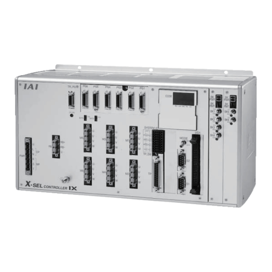
Part 1 Installation Chapter 4 Name and Function of Each Part 1. Front View of Controller PX Type (Standard Specification), 4 axes (SCARA axes only) PX Type (Standard Specification), expanded by 2 additional linear movement axes, with I/O brake unit... - Page 41 Part 1 Installation QX Type (Global Specification), 4 axes (SCARA axes only) QX Type (Global Specification), expanded by 2 additional linear movement axes, with I/O brake unit...
- Page 42 Part 1 Installation FG terminal This terminal is used to ground FG on the enclosure. The enclosure is connected to PE in the AC input part inside the controller. FG Terminal Specifications Item Description M4 3-point SEMS screw, 5 mm Name Cable size 2.0 ~ 5.5 mm...
- Page 43 Part 1 Installation AC-power input A 200-VAC, single-phase/three-phase input connector consisting of six connector terminals including motor power terminals, control power terminals and a PE terminal. Note) Select the single-phase input specification or three-phase input specification, whichever is applicable, for motor drive power. The standard type only comes with a terminal block.
- Page 44 Part 1 Installation Encoder/axis-sensor This connector is used to connect the actuator encoder and axis sensors such connector as LS, CREEP and OT. * LS, CREEP and OT sensors are optional. The connectors are assigned to axis 1, axis 2, and so on, from the right. Encoder/Axis-sensor Connector Specifications Item Overview...
- Page 45 Switch Note 1: The safety gate switch will not function if this switch is not set correctly. Note 2: IAI’s standard teaching pendants cannot be used with Q type controllers. Note 3: TP-SW is not available on QX type controllers.
- Page 46 Part 1 Installation Teaching connector The teaching interface connects IAI’s teaching pendant or a PC to enable operation and setting of your equipment from the teaching pendant/PC. The physical interface consists of a RS232C system based on a 25 pin D-sub connector.
- Page 47 Part 1 Installation Interface Specifications of Teaching Serial Interface Item Direction Signal name Details Frame ground Transmitted data Received data Request to send Clear to send Equipment ready Signal ground Not connected RSVTBX1 RSV signal line for generic teaching pendant RSVTBX2 RSV signal line for generic teaching pendant...
- Page 48 Part 1 Installation [10] System I/O connector This I/O connector is used to control the safety actions of the controller. With the global specification, a safety circuit conforming to a desired safety category of up to level 4 can be configured using this connector and an external safety circuit.
- Page 49 Part 1 Installation [11] Panel window This window consists of a 4-digit, 7 segment LED display and five LED lamps that indicate the status of the equipment. For the information shown on the display, refer to 2, “Explanation of Codes Displayed on the Panel Window”...
- Page 50 Part 1 Installation I/O Interface List Pin No. Category Port No. Function Cable color +24 V input Brown-1 The functions are at the time Program start Red-1 of shipment. The functions General purpose input Orange-1 assigned to port Nos. 000 to General purpose input Yellow-1 015, 300 to 310, 313 and...
- Page 51 Part 1 Installation [14] General RS232C port Channel 1 of the two-channel RS232C port provided for connection of connector 1 general RS232C equipment. (Refer to I/O parameter Nos. 201 to 203.) [15] General RS232C port Channel 2 of the two-channel RS232C port provided for connection of connector 2 general RS232C equipment.
- Page 52 Part 1 Installation [19] Brake power input This connector is used to input the power for SCARA brake control. 24 VDC connector must be supplied externally. (SCARA axis only) Connect the SCARA-axis brake power to both the brake power cable from the SCARA robot and this connector.
- Page 53 Part 1 Installation [22] Brake switch (Linear This alternate switch with lock is used to release the axis brake. To operate movement axis only) the switch, pull it toward you and tilt. Tilting the switch upward (RLS side) will release the brake forcibly, while tilting it downward (NOM) will enable the controller to release the brake.
-
Page 54: Explanation Of Codes Displayed On The Panel Window
Part 1 Installation 2. Explanation of Codes Displayed on the Panel Window Application Display Priority (*1) Description AC power is cut off (including momentary power failure or drop in power source voltage). System down level error Writing data to the flash ROM. Emergency stop is being actuated (except during the update mode). -
Page 55: Core
Part 1 Installation Core Display Priority (*1) Description AC power is cut off (including momentary power failure or drop in power source voltage) Coldstart level error Coldstart level error Operationcancellation level error Operationcancellation level error Message level error Message level error Application update mode Application update is in progress Application update has completed... -
Page 56: Current Monitor And Variable Monitor
Part 1 Installation Current Monitor and Variable Monitor Other parameter Nos. 49 and 50 can be set up to monitor currents or variables on the panel window. (1) Current monitor Currents of up to four axes having continuous axis numbers can be monitored. Parameter settings Other parameter No. - Page 57 Part 1 Installation (2) Variable monitor The contents of global integer variables can be displayed on the panel window. Positive integers of 1 to 999 can be displayed. Parameter settings Other parameter No. 49 = 2 Other parameter No. 50 = Variable number of the global integer variable to be monitored When data is written to the flash ROM or a software reset (restart) is executed after the parameter values have been input, the panel window will show the content of the global integer variable, instead of “ready status”...
-
Page 58: Chapter 5 Specifications
17 bit rotation data backup absolute encoder Resolution: 14 bits under both methods (16384 pulses) Batteries Absolute-data backup battery: AB-5 made by IAI System-memory backup battery: CR2032 Speed setting 1 mm/sec to 3000 mm/sec (Varies according to the applicable model.) Acceleration/deceleration 0.01 G to 3 G (Varies according to the applicable model.) - Page 59 16 points or 32 points, NPN or PNP (set before shipment) RS232C port for teaching Enabled only in the manual operation mode. serial interface IAI’s dedicated teaching pendant or ANSI teaching pendant (selected by a switch) RS232C port for general Dedicated 2 channel RS232C, 9 pin DTE specification PC connection Half-duplex at speeds up to 115.2 kbps (1 channel) or up to 76.8 kbps...
- Page 60 17 bit rotation data backup absolute encoder Resolution: 14 bits under both methods (16384 pulses) Batteries Absolute-data backup battery: AB-5 made by IAI System-memory backup battery: CR2032 Speed setting 1 mm/sec to 3000 mm/sec (Varies according to the applicable model.) Acceleration/deceleration 0.01 G to 3 G (Varies according to the applicable model.)
- Page 61 16 points or 32 points, NPN or PNP (set before shipment) RS232C port for teaching Enabled only in the manual operation mode. serial interface IAI’s dedicated teaching pendant or ANSI teaching pendant (selected by a switch) RS232C port for general Dedicated 2 channel RS232C, 9 pin DTE specification PC connection Half-duplex at speeds up to 115.2 kbps (1 channel) or up to 76.8 kbps...
-
Page 62: External I/O Specifications
Part 1 Installation 2. External I/O Specifications 2.1. NPN Specification (1) Input part External Input Specifications (NPN Specification) Item Specification Input voltage 24 VDC 10% Input current 7 mA per circuit ON voltage --- 16.0 VDC min. ON/OFF voltage OFF voltage --- 5.0 VDC max. Insulation method Photocoupler insulation [1] No voltage contact (minimum load of approximately 5 VDC/1 mA) - Page 63 Part 1 Installation (2) Output part External Output Specifications (NPN Specification) Item Specification Load voltage 24 VDC TD62084 (or equivalent) Maximum load current 100 mA per point, 400 mA per 8 ports Note) Leakage current 0.1 mA max. per point Insulation method Photocoupler insulation [1] Miniature relay...
-
Page 64: Pnp Specification
Part 1 Installation 2.2. PNP Specification (1) Input part External Input Specifications (PNP Specification) Item Specification Input voltage 24 VDC 10% Input current 7 mA per circuit ON voltage --- 8 VDC max. ON/OFF voltage OFF voltage --- 19 VDC min. Insulation method Photocoupler insulation [1] No-voltage contact (minimum load of approx. - Page 65 Part 1 Installation (2) Output part External Output Specifications Item Specification Load voltage 24 VDC TD62784 (or equivalent) Maximum load current 100 mA per point, 400 mA per 8 ports Note) Leakage current 0.1 mA max. per point Insulation method Photocoupler insulation [1] Miniature relay External devices...
-
Page 66: Power Source Capacity And Heat Output
CC-Link 0.5 W 0 1 Network module Profibus-DP 1.75 W 0 1 Ethernet 2.25 W 0 1 IAI standard 1.5 W Teaching 0 1 pendant ANSI 4.08 W 0 1 Brake *3 Per axis 2.5 W 5.8 W... - Page 67 Part 1 Installation *2 The number of fan units varies depending on the controller specification. The number of fan units varies as follows in accordance with the number of controller axes (whether or not linear movement axis is added) and use/no-use of any expansion I/O board. Controller Specifications and Number of Fan Units Without expansion SCARA axes only...
- Page 68 Part 1 Installation (2) Power consumption and heat output of the motor drive part Both the power consumption and heat output of the motor drive part will vary depending on the number of axes connected to the controller and wattage configuration. The table below lists per axis motor power consumptions.
- Page 69 Part 1 Installation List of Motor Drive Powers Power [W] Output stage loss Power 0.6 (rated output) [Power factor] [VA NN2515 NN3515 TNN3015 615.8 1026.3 24.75 TNN3515 UNN3015 UNN3515 NN50 NN60 HNN5020 1122.8 1871.3 44.12 HNN6020 INN5020 INN6020 NN70 NN80...
- Page 70 Standard DIO Options: DeviceNet, teaching pendant (IAI’s standard type) Control power supply capacity {13.19 + 2.63 3 + (1 + 1.5) 6 + 2.4 5 + 2.5 1 + 1.5} 0.7 0.6 124.0 [VA]...
- Page 71 The power supply capacity and heat output of a SCARA-axis controller (4-axis specification without additional linear movement axis) are shown below. All figures assume use of a standard DIO board, with DeviceNet support and a teaching pendant (IAI’s standard type) added as options.
-
Page 72: External Dimensions
Part 1 Installation 4. External Dimensions List of External Dimension Drawings The external controller dimensions vary depending on the SCARA model (arm length) and whether or not a linear movement axis or expansion I/O board is used, among others. The table below lists the external dimension drawing numbers applicable to the respective specifications. NN2515 NN3515 TNN2515... - Page 73 Part 1 Installation PX/QX Type (Three-phase Standard Specification, Single-phase Global Specification, Single-phase Standard Specification) Controller Fig. 4-1 PX/QX Type (Three-phase Standard Specification, Single-phase Global Specification, Single-phase Standard Specification) 4-axis specification, SCARA arm length 120/150/180 mm, without expansion I/O board (80) 3-5 49.5...
- Page 74 Part 1 Installation Fig. 4-3 PX/QX Type (Three-phase Standard Specification, Single-phase Global Specification, Single-phase Standard Specification) 5/6-axis specification, SCARA arm length 120/150/180 mm, without expansion I/O board, with incremental linear movement axis without brake 3-5 Example of applicable model: X-SEL-PX-NNN1205-200I-200I-N1-EEE-2-3 Fig.
- Page 75 Part 1 Installation Fig. 4-5 PX/QX Type (Three-phase Standard Specification, Single-phase Global Specification, Single-phase Standard Specification) 4-axis specification, SCARA arm length 250 to 600 mm, without expansion I/O board 3-5 59.5 59.5 Example of applicable model: X-SEL-PX-NNN2515-N1-EEE-2-3 Fig. 4-6 PX/QX Type (Three-phase Standard Specification, Single-phase Global Specification, Single-phase Standard Specification) ...
- Page 76 Part 1 Installation Fig. 4-7 PX/QX Type (Three-phase Standard Specification, Single-phase Global Specification, Single-phase Standard Specification) 5/6-axis specification, SCARA arm length 250 to 600 mm, without expansion I/O board 5/6-axis specification, SCARA arm length 120/150/180 mm, without expansion I/O board, with absolute linear movement axis or linear movement axis with brake ...
- Page 77 Part 1 Installation QX Type (Three-phase Global Specification) Controller Fig. 4-9 QX Type (Three-phase Global Specification) 4-axis specification, SCARA arm length 120/150/180 mm, without expansion I/O board (80) 3-5 125.3 Example of applicable model: X-SEL-QX-NNN1205-N1-EEE-2-3 Fig. 4-10 QX Type (Three-phase Global Specification) ...
- Page 78 Part 1 Installation Fig. 4-11 QX Type (Three-phase Global Specification) 5/6-axis specification, SCARA arm length 120/150/180 mm, without expansion I/O board, with incremental linear movement axis without brake 3-5 45.5 45.5 Example of applicable model: X-SEL-QX-NNN1205-200I-200I-N1-EEE-2-3 Fig. 4-12 QX Type (Three-phase Global Specification) ...
- Page 79 Part 1 Installation Fig. 4-13 QX Type (Three-phase Global Specification) 4-axis specification, SCARA arm length 250 to 600 mm, without expansion I/O board 3-5 Example of applicable model: X-SEL-QX-NNN2521-N1-EEE-2-3 Fig. 4-14 QX Type (Three-phase Global Specification) 4-axis specification, SCARA arm length 250 to 600 mm, with expansion I/O board 3-5 29.5 29.5...
- Page 80 Part 1 Installation Fig. 4-15 QX Type (Three-phase Global Specification) 5/6-axis specification, SCARA arm length 250 to 600 mm, without expansion I/O board 5/6-axis specification, SCARA arm length 120/150/180 mm, without expansion I/O board, with absolute linear movement axis or linear movement axis with brake ...
-
Page 81: Chapter 6 Safety Circuit
Part 1 Installation Chapter 6 Safety Circuit The circuit configuration for embodying safety actions such as emergency stop is different between the standard specification and global specification of the X-SEL controller. The standard controller has a built-in drive source cutoff circuit conforming to safety category B. The global controller has no built-in drive source cutoff circuit so that the user can configure an external safety circuit appropriate for their equipment configuration. -
Page 82: Safety Circuit For Px Type (Standard Specification) Controller
2. Safety Circuit for PX Type (Standard Specification) Controller The PX type controller has a built-in drive source cutoff circuit just like IAI’s other controllers. The drive source cutoff circuit consists of a relay and conforms to safety category B. If your equipment must meet a higher safety category, use the QX type (global specification) controller explained later. - Page 83 Part 1 Installation With the PX type, use only the signals shown in the shaded fields of the table for connection with the safety switches. Ensure that the specified pins are wired correctly, as incorrect wiring will compromise the safety mechanisms of the controller.
-
Page 84: Safety Circuit For Qx Type (Global Specification) Controller
It is recommended that the control power supply be wired from the same power source as the motor power supply at a point before the drive-source cutoff part is connected. Please note that IAI is not liable for any losses arising from a malfunction of the safety circuit configured by the user. - Page 85 Part 1 Installation Terminal Assignments Signal Overview Details name External contact error input (paired with No. 18) To fused-contact Connected to the fused contact detection contacts of detection circuit the safety circuit. To EMG status Emergency stop detection input EMGin of safety circuit +24 V 24 V power output for emergency stop detection input...
- Page 86 Part 1 Installation EMG1/EMG2, ENB1/ENB2 EMG1 (line+)/(line-) and EMG2 (line+)/(line-) are redundant emergency stop control lines. ENB1 (line+)/(line-) and ENB2 (line+)/(line-) are redundant enabling control lines. Use these lines to cut off the external drive source. Since they are completely dry signal lines, configure a relay circuit using an external power source.
- Page 87 Part 1 Installation QX Type X-SEL Controller Power supply part Digital control part Not installed External emergency-stop reset contact output AC cutoff relay DC bus Rectifier To power stage Power-on reset MPSDWN bit Teaching pendant Power error Mushroom emergency- stop switch EMG SW contact 1 EMG SW...
- Page 88 Part 1 Installation External Emergency Stop Circuit 200-VAC, three- phase Relay Contactor (NEO SC) Contactor (NEO SC) Reset switch External emergency-stop switch External EMG switch Safety relay unit contact 1 (G9SA-301 by Omron) External EMG switch contact 2 Safety gate switch External SGATE contact 1...
-
Page 89: Timing Chart Of Safety Circuit For Qx-Type Sel Controller
Part 1 Installation 4. Timing Chart of Safety Circuit for QX-type SEL Controller A timing chart of the safety circuit for QX-type SEL controller is shown below. The points in time shown in this timing chart are: “[1] Power on,” “[2] Emergency stop,” “[3] Power on without cancelling emergency stop,”... - Page 90 Part 1 Installation [2] Emergency stop 200-VAC control power Normal CPU start I/O output signal: Port No. 301 Ready output Rdy (system I/O) SDN (system I/O) EMG1, EMG2 (system I/O) Emergency stop SW = ON Emergency stop SW = OFF ENB1, ENB2 (system I/O) Occurrence of secret level error Occurrence of message level error...
- Page 91 Part 1 Installation [3] Power on without cancelling emergency stop 200-VAC control power Normal CPU start I/O output signal: Port No. 301 Ready output Rdy (system I/O) SDN (system I/O) EMG1, EMG2 (system I/O) Rdy and SDN = ON due to cancellation of emergency stop ENB1, ENB2 (system I/O) Occurrence of secret level error...
- Page 92 Part 1 Installation [4] Enable operation 200-VAC control power Normal CPU start I/O output signal: Port No. 301 Ready output Rdy (system I/O) SDN (system I/O) EMG1, EMG2 (system I/O) ENB1, ENB2 (system I/O) Enable SW = ON Enable SW = OFF Occurrence of secret level error Occurrence of message level error Occurrence of operation cancellation level error...
- Page 93 Part 1 Installation [5] System shutdown level error 200-VAC control power Normal CPU start I/O output signal: Port No. 301 Ready output Rdy (system I/O) SDN (system I/O) EMG1, EMG2 (system I/O) ENB1, ENB2 (system I/O) Occurrence of secret level error Occurrence of message level error Occurrence of operation cancellation level error Occurrence of cold start level error...
- Page 94 Part 1 Installation [6] Cold start level error 200-VAC control power Normal CPU start I/O output signal: Port No. 301 Ready output Rdy (system I/O) The timings of SDN and Rdy may be slightly early or late depending on the nature of the error. SDN (system I/O) EMG1, EMG2 (system I/O) ENB1, ENB2 (system I/O)
- Page 95 Part 1 Installation [7] Operation cancellation level error 200-VAC control power Normal CPU start I/O output signal: Port No. 301 Ready output Rdy (system I/O) SDN (system I/O) EMG1, EMG2 (system I/O) ENB1, ENB2 (system I/O) Occurrence of secret level error Occurrence of message level error Occurrence of operation cancellation level error Rdy and SDN are not affected by errors of...
- Page 96 Part 1 Installation [8] Power on (in combination with drive-source cutoff reset input) 200-VAC control power Normal CPU start I/O input signal: Port No. 14 Drive-source cutoff reset input I/O output signal: Port No. 301 Ready output Rdy (system I/O) SDN (system I/O) EMG1, EMG2 (system I/O) ENB1, ENB2 (system I/O)
- Page 97 Part 1 Installation [9] Emergency stop (in combination with drive-source cutoff reset input) 200-VAC control power Normal CPU start I/O input signal: Port No. 14 Drive-source cutoff reset input I/O output signal: Port No. 301 Ready output Rdy (system I/O) SDN (system I/O) EMG1, EMG2 (system I/O) Emergency stop SW = ON Emergency stop SW = OFF...
-
Page 98: Chapter 7 System Setup
Part 1 Installation Chapter 7 System Setup 1. Connection Method of Controller and Actuator Connection Diagram for PX Type (Standard Specification) Emergency- stop switch Three-phase specification Single-phase 200 to 230 VAC power supply Teaching-pendant type Enable Three-phase 200 to 230 VAC switch power supply switch... - Page 99 Part 1 Installation Connection Diagram for QX Type (Global Specification) Three-phase specification Single-phase 200 to 230 VAC power supply Three-phase 200 to 230 VAC power supply Single-phase specification Single-phase 200 to 230 VAC power supply Absolute-encoder backup Three-phase 200 to 230 VAC battery enable/disable switch power supply for linear movement axis...
- Page 100 Part 1 Installation The positions of motor connectors and encoder connectors vary depending on the SCARA type. The figure below shows where the motor connectors and encoder connectors are located for each SCARA type, as viewed from the front side of the controller. Arm length 700/800 High-speed type (NSN**----) Encoder connector...
- Page 101 Switch IA-T-X, IA-T-XD teaching pendant Note 1: TP-SW is not available on QX type controllers. Note 2: IAI’s standard teaching pendants and standard PC cables cannot be used with QX type controllers. [6] Turn on the controller power. [7] If an absolute linear movement axis is connected, set the absolute-encoder backup battery enable/disable switch to the top position (ENB side).
-
Page 102: I/O Connection Diagram
Part 1 Installation 2. I/O Connection Diagram NPN specification Pin No. Category Port No. Function (factory setting) (Note) +24-V input Program start General-purpose input General-purpose input General-purpose input General-purpose input General-purpose input General-purpose input Program specification (PRG No. 1) Program specification (PRG No. 2) Program specification (PRG No. - Page 103 Part 1 Installation PNP specification Pin No. Category Port No. Function (factory setting) +24-V input Program start General-purpose input General-purpose input General-purpose input General-purpose input General-purpose input General-purpose input Program specification (PRG No. 1) Program specification (PRG No. 2) Program specification (PRG No. 4) Program specification (PRG No.
- Page 104 Part 1 Installation I/O Flat Cable Flat cable: KFX-50 (S) (Color) (Kaneko Cord) Connector not attached Flat cable (50 cores) Socket (with strain relief): XG4M-5030-T (Omron) Color Color Color Color Color Brown-1 Brown-2 Brown-3 Brown-4 Brown-5 Red-1 Red-2 Red-3 Red-4 Red-5 Orange-1 Orange-2...
-
Page 105: Multipoint Dio Board
Part 1 Installation 3. Multipoint DIO Board This board is a multipoint DIO board for XSEL controllers on which 48 input points and 48 output points are provided. Overview 3.1.1 Features [1] 96 points can be input/output using a single board. One board provides 48 input points and 48 output points to enable multipoint I/O control with your XSEL controller. -
Page 106: External Interface Specifications
Part 1 Installation External Interface Specifications 3.3.1 External DIO Interface Terminal Assignment Overview or multipoint DIO interface specifications Item Overview Remarks Applicable connector Half-pitch flat connector, 100 pins HIF6-100PA-1.27DS (Hirose) Connector name External DIO connector The power supply is separated for every 24 External power supply 24 VDC ... -
Page 107: Multipoint I/O Board Connection Cables
Part 1 Installation Multipoint I/O Board Connection Cables Cable 1 Cable 2 Category Pin No. Color Port No. Function Category Pin No. Color Port No. Function 24-VDC for external power Brown-1 supply Brown-1 Alarm output Pin Nos. 2 to 25/51 to 74 Red-1 Program start Red-1... -
Page 108: Multipoint I/O Board Connection Cables
Part 1 Installation Multipoint I/O Board Connection Cables Model: CB-X-PIOH020 No connector Socket: HIF6-100D-1.27R (Hirose) Flat cable (50 cores) UL2651 AWG28 x 2 Cable 1 (pins 1 to 50) Cable 2 (pins 51 to 100) -
Page 109: I/O Circuits
Part 1 Installation I/O Circuits 3.6.1 Input Input specifications Item Specification (common to PNP/NPN) External power-supply voltage 24 VDC 10% Input current Max. 7 mA/1 point Leak current Max. 7 mA/1 point Input circuit NPN specification External power Internal supply circuit... - Page 110 Part 1 Installation 3.6.2 Output Output specifications Specification Output element Transistor array NPN specification: TD62084AF by Toshiba PNP specification: TD62784AF by Toshiba External power-supply voltage 24 VDC 10% Maximum load current Max. 50 mA/1 point (Max. 400 mA/24 points): *1 Leak current Max.
-
Page 111: Chapter 8 How To Perform An Absolute Encoder Reset Of A Direct Movement Axis (Absolute Specification)
In the case of a synchro controller, refer to “ Absolute Reset of A Synchro Controller” in Appendix. 1. Preparation (1) PC A PC in which IAI’s X-SEL PC software (X_SEL.exe) has been installed (2) Connection cable (the cable supplied with the PC software) RS232C cross cable (PC end: female 9 pin, Controller end: male 25 pin) (3) All adjustments other than the absolute reset must have been completed. - Page 112 Part 1 Installation (6) The X-SEL PC software window will be displayed. Clicking the [OK] button will clear the error message. (7) From the [Monitor (M)] menu, select [Detailed Error Information (E)] to check the current error status. In the case of an encoder battery error, the following will be displayed (when axis 4 is using an absolute encoder).
- Page 113 Part 1 Installation (8) From the [Controller (C)] menu, select [Absolute Reset (Linear Movement Axis) (A)]. (9) When a [Warning] dialog box is displayed, click the [OK] button.
- Page 114 Part 1 Installation (10) The [Abs. Encoder Reset] dialog box will be displayed. Click here to select the axis for which you wish to perform an absolute reset. (11) Clicking the [Encoder Rotation Data Reset 1] button will display a [Warning] dialog box. Click the [Yes] button.
- Page 115 Part 1 Installation (12) Another [Warning] dialog box will be displayed. Click the [Yes] button. (13) When the processing of “encoder rotation data reset 1” is complete, the red arrow will move to the next item. Press the following processing buttons one by one (the red arrow will move to the next item when each process is completed): 1.
- Page 116 Part 1 Installation (15) When the [Confirmation] dialog box is displayed, click the [Yes] button and restart the controller. (Note) Commencing the operation without first executing a software reset or reconnecting the power may generate an “Error No. C70, ABS coordinate non-confirmation error.” (16) If no other error is present, the controller’s 7 segment LED display will show “rdy.”...
-
Page 117: Chapter 9 Maintenance
Part 1 Installation Chapter 9 Maintenance Routine maintenance and inspection are necessary so that the system will operate properly at all times. Be sure to turn off the power before performing maintenance or inspection. The standard inspection interval is six months to one year. If the environment is adverse, however, the interval should be shortened. -
Page 118: Spare Consumable Parts
Part 1 Installation 2. Spare Consumable Parts Without spare parts, a failed controller cannot be repaired even when the problem is identified quickly. We recommend that you keep the following consumable parts as spares: Consumable parts Cables System memory backup battery: CR2032 (Note 1) --- Must be replaced after approx. 1.5 years (Note 2) ... -
Page 119: Replacement Procedure For System Memory Backup Battery
Part 1 Installation 3. Replacement Procedure for System Memory Backup Battery Backing up the system memory If “Other parameter No. 20, Backup battery installation function type” is set to “2” (installed), the following SRAM data in the X-SEL Controller will be backed up by the system memory backup battery on the panel board: ... - Page 120 Part 1 Installation Battery Replacement Procedure Remove the 7 segment LED panel from the controller. Slide the panel upward and pull it toward you to remove. Press the center of the battery using a finger, as shown. The battery will come off from the holder. Install a new battery into the holder.
- Page 121 Part 1 Installation (8) When the replacement of system memory backup battery is complete, confirm that the battery is installed securely and then turn on the controller power. (9) Revert “Other parameter No. 20, Backup battery installation function type” to the value recorded in step 2, transfer the setting to the controller, and then perform a flash ROM write.
-
Page 122: Replacement Procedure For Absolute-Encoder Backup Battery For Linear Movement Axis
Part 1 Installation 4. Replacement Procedure for Absolute-Encoder Backup Battery for Linear Movement Axis The replacement procedure will vary depending on if errors are present at the time of replacement and if so, which errors are present (Nos. A23, 914, CA2). ... - Page 123 Part 1 Installation (5) Insert a new battery into the holder and plug in the battery connector. (6) Turn on the controller power. (7) Set the absolute data backup battery enable/disable switch to the top (ENB) position. (Note) This operation is not required if no error has occurred or an A23 error has occurred. (8) Turn off the controller power and install the brake switch panel with the screws.
- Page 124 Part 1 Installation (15) From the [Controller (C)] menu on the PC software screen, select [Software Reset (R)], and restart the controller. Confirmation (Note) Commencing the operation without first executing a software reset or reconnecting the power may generate the following errors: Error No.
-
Page 125: Part 2 Operation
Part 2 Operation Part 2 Operation Chapter 1 Operation How to Start a Program With the X-SEL controller, the stored programs can be started using four methods. Of these methods, two are mainly used to debug programs or perform trial operations, while the remaining two are used in general applications on site. -
Page 126: Starting A Program By Auto Start Via Parameter Setting
Part 2 Operation 1. Starting a Program by Auto Start via Parameter Setting I/O parameter No. 33 (input function selection 003) = 1 (default factory setting) This parameter is set using the teaching pendant or PC software. Set the number of the program you wish to start automatically in other parameter No. -
Page 127: Starting Via External Signal Selection
Part 2 Operation 2. Starting via External Signal Selection Select a desired program number externally and then input a start signal. (1) Flow chart External device Controller Power ON Power ON When the READY signal turns ON, the RDY Ready output lamp (green) on the controller front panel will READY signal ON READY signal... - Page 128 Part 2 Operation (2) Timing chart [1] Start of program T1: Duration after the ready output turns ON until input of Ready output external start signal is permitted Program 1 Program 2 T1 = 10 msec min. Program number input T2: Duration after the program number is input until input of external start signal is permitted External start...
-
Page 129: Drive Source Recovery Request And Operation Pause Reset Request
Part 2 Operation 3. Drive Source Recovery Request and Operation Pause Reset Request (1) Drive source recovery request [1] How to request a drive source recovery A drive source recovery request can be issued using one of the following methods: ... -
Page 130: Chapter 2 Specoal Function
Part 2 Operation Chapter 2 Special Function 1. Driver Overload Warning Function Setting the motor estimated raised temperature that causes the driver overload error as 100%, the driver overload warning (message level error) will be detected when the load rate (hereafter described as the overload level) exceeded the value set in the parameter. - Page 131 Part 2 Operation [Reference: Check of Overload Level] The overload level during the motor operation can be checked in the PC Interface Software for XSEL. [1] Click “Servo addition Datamonitor” in “Monitor” menu. [2] Set the monitor type in “Servo addition Datamonitor” window to “01: Motor load factor.”...
- Page 132 Part 2 Operation ● Axis-Specific Parameters Default value Access Parameter name Input range Unit Remarks (Reference) Right Set in % from the driver overload error load level (Invalid when 100) (Main application Ver. 0.65 or later) * To prevent motor burnout, the startup initial temperature is assumed high considering the hot start for the OLWL (used be OVLD)
-
Page 133: Part 3 Controller Data Structure
Part 3 Controller Data Structure Part 3 Controller Data Structure The controller data consists of parameters as well as position data and application programs used to implement SEL language. X-SEL Controller Data Structure Driver Main Driver Driver Driver Communication SEL language Parameters Position Application... -
Page 134: Chapter 1 How To Save Data
Part 3 Controller Data Structure Chapter 1 How to Save Data Since the X-SEL controller uses flash memory, some data are saved by battery backup while others are saved in the flash memory. When data is transferred from the PC software or teaching pendant to the controller, the data is only written to the main CPU memory as shown in the diagram below and will be erased once the controller is powered down or reset. -
Page 135: Controller With Increased Memory Size (With Gateway Function)
Part 3 Controller Data Structure Since the programs, parameters and symbols are read from the flash memory at restart, the data in the temporary memory will remain the same as the original data before edit unless the edited data are written to the flash memory. -
Page 136: When The System Memory Backup Battery Is Not Used
Part 3 Controller Data Structure 2. When the System Memory Backup Battery is Not Used Controller without Increased Memory Size Other parameter No. 20 = 0 (System memory backup battery not installed) Data edited on the PC Data will be retained while the power is Data will be retained even after the or teaching pendant on and cleared upon reset... - Page 137 Part 3 Controller Data Structure Controller with Increased Memory Size (with Gateway Function) (Other parameter No. 20 = 0 (System-memory backup battery not installed)) Data edited on the PC Data will be retained while the power Data will be retained even after the or teaching pendant is on and cleared upon reset power is turned off...
-
Page 138: Points To Note
Part 3 Controller Data Structure 3. Points to Note Point to note when transferring data and writing to the flash memory Never turn off the main power while data is being transferred or written to the flash memory. The data will be lost and the controller operation may be disabled. Point to note when saving parameters to a file The encoder parameters are stored in the EEPROM of the actuator’s encoder itself (unlike other parameters, they are not stored in the EEPROM of the controller). - Page 139 Part 3 Controller Data Structure Note on increased parameters On controllers with increased memory size (with gateway function), the number of parameters has been increased. Number of parameters Without increased With increased memory size memory size All-axis common Axis specific Drive Encoder I/O device...
-
Page 140: Chapter 2 X-Sel Language Data
Part 3 Controller Data Structure Chapter 2 X-SEL Language Data 1. Values and Symbols Used in SEL Language List of Values and Symbols Used The functions required in a program are represented by values and symbols. Function Global range Local range Remarks Varies depending on Input port... -
Page 141: I/O Ports
Part 3 Controller Data Structure The variables and flags in the global range will be retained even after the controller power is turned off (when other parameter No. 20 is set to “2.” Refer to Chapter 1, “How to Save Data,” of Part 3). ... -
Page 142: Virtual I/O Ports
Part 3 Controller Data Structure Virtual I/O Ports (1) Virtual input ports Port No. Function 7000 Always OFF 7001 Always ON 7002 Voltage low warning for system memory backup battery 7003 Abnormal voltage of system memory backup battery 7004 (For future expansion = Use strictly prohibited) 7005 (For future expansion = Use strictly prohibited) 7006... - Page 143 Part 3 Controller Data Structure (2) Virtual output ports Port No. Function Latch cancellation output for a latch signal indicating that all operation cancellation factor is present 7300 (port 7011. The latch is cancelled only when operation cancellation factor is no longer present. 7300 will be turned OFF following an attempt to cancel latch) 7301 ~ 7380 (For future expansion = Use strictly prohibited)
-
Page 144: Flags
Part 3 Controller Data Structure Flags Contrary to its common meaning, the term “flag” as used in programming means “memory.” Flags are used to set or reset data. They correspond to “auxiliary relays” in a sequencer. Flags are divided into global flags (Nos. 600 to 899) that can be used in all programs, and local flags (Nos. 900 to 999) that can be used only in each program. -
Page 145: Variables
Part 3 Controller Data Structure Variables (1) Meaning of variable “Variable” is a technical term used in software programming. Simply put, it means “a box in which a value is put.” Variables can be used in many ways, such as putting in or taking out a value and performing addition or subtraction. - Page 146 Part 3 Controller Data Structure (2) Types of variables Variables are classified into two types, as follows: [1] Integer variables These variables cannot handle decimal places. [Example] 1234 Integer variable box Variable box 1 200 ~ 299 Integer variable number Can be used in all programs “Global integer variables”...
- Page 147 Part 3 Controller Data Structure [3] Variables with “*” (asterisk) (indirect specification) An “*” (asterisk) is used to specify a variable. In the following example, the content of variable box 1 will be put in variable box 2. If variable box 1 contains “1234,”...
-
Page 148: Tags
Part 3 Controller Data Structure Tags The term “tag” means “heading.” Tags are used in the same way you attach labels to the pages in a book you want to reference frequently. A tag is a destination specified in a jump command “GOTO.” Command Operand 1 Tag number (Integer between 1 and 256) -
Page 149: Subroutines
Part 3 Controller Data Structure Subroutines By taking out the parts of a program that are used repeatedly and registering them as “subroutines,” the same processing can be performed with fewer steps (a maximum of 15 nests are accommodated). They are used only in each program. -
Page 150: Symbols
Part 3 Controller Data Structure Symbols In the X-SEL Controller, values such as variable numbers and flag numbers can be handled as symbols. For the method to edit symbols, refer to “Editing Symbols” in the operation manual for X-SEL teaching pendant or “Symbol Edit Window”... -
Page 151: Axis Specification
Part 3 Controller Data Structure 1.10 Axis Specification Axes can be specified based on axis number or axis pattern. (1) Axis numbers and how axes are stated Each of multiple axes is stated as follows: Axis number How axis is stated Axis 1 Axis 2 Axis 3... - Page 152 Part 3 Controller Data Structure (2) Axis pattern Whether or not each axis will be used is indicated by “1” or “0.” (Upper) (Lower) Axis number Axis 6 Axis 5 Axis 4 Axis 3 Axis 2 Axis 1 Used Not used [Example] When axes 1 and 2 are used Axis 2...
-
Page 153: Position Part
Part 3 Controller Data Structure X-SEL language consists of a position part (position data = coordinates, etc.) and a command part (application program). 2. Position Part As position data, coordinates, speeds, accelerations and decelerations are set and stored. Standard *1, 2 Standard 0.3 G 1 ~ 2000 mm/sec... -
Page 154: Command Part
Part 3 Controller Data Structure 3. Command Part The primary feature of SEL language is its very simple command structure. Since the structure is simple, there is no need for a compiler (to translate into computer language) and high speed operation is possible via an interpreter (the program runs as commands are translated). -
Page 155: Extension Condition
Part 3 Controller Data Structure Extension Condition Conditions can be combined in a complex manner. (SEL language) AND extension (Ladder diagram) Command Input Extension Output Condition condition Operand Operand condition Command Condition 1 Condition 2 Condition Operand Operand Condition 3 Command Condition OR extension Command... -
Page 156: Part 4 Commands
Part 4 Commands Part 4 Commands Chapter 1 List of SEL Language Command Codes By Function Variables can be specified indirectly in the operand 1, operand 2 and output fields. Symbols can be input in the condition, operand 1, operand 2 and output fields. The input items in ( ) under operand 1 and operand 2 are optional. - Page 157 Part 4 Commands Operation type in the output field Command was executed successfully, ZR: Operation result is zero, Operation is complete, CP: Command part has passed, TU: Time up Operand 1 = Operand 2, NE: Operand 1 Operand 2, Operand 1 >...
- Page 158 Part 4 Commands Operation type in the output field Command was executed successfully, ZR: Operation result is zero, Operation is complete, CP: Command part has passed, TU: Time up Operand 1 = Operand 2, NE: Operand 1 Operand 2, Operand 1 >...
- Page 159 Part 4 Commands Operation type in the output field Command was executed successfully, ZR: Operation result is zero, Operation is complete, CP: Command part has passed, TU: Time up Operand 1 = Operand 2, NE: Operand 1 Operand 2, Operand 1 >...
- Page 160 Part 4 Commands Operation type in the output field Command was executed successfully, ZR: Operation result is zero, Operation is complete, CP: Command part has passed, TU: Time up Operand 1 = Operand 2, NE: Operand 1 Operand 2, Operand 1 >...
- Page 161 Part 4 Commands Operation type in the output field Command was executed successfully, ZR: Operation result is zero, Operation is complete, CP: Command part has passed, TU: Time up Operand 1 = Operand 2, NE: Operand 1 Operand 2, Operand 1 >...
- Page 162 Part 4 Commands RC Gateway Function Commands (Controllers with Gateway Function Only) * For the RC gateway function commands, refer to “Operation Manual for X-SEL Controller P/Q/PX/QX RC Gateway Function.” Operation type in the output field Operand 1 = Operand 2, NE: Operand 1 Operand 2, Command was executed successfully, Operand 1 >...
- Page 163 Part 4 Commands Alphabetical Order Operation type in the output field Operand 1 = Operand 2, NE: Operand 1 Operand 2, Command was executed successfully, Operand 1 > Operand 2, GE: Operand 1 Operand 2, Operation result is zero, PE: Operation is complete, Command part has passed, TU: Time up Operand 1 <...
- Page 164 Part 4 Commands Operation type in the output field Command was executed successfully, ZR: Operation result is zero, Operation is complete, CP: Command part has passed, TU: Time up Operand 1 = Operand 2, NE: Operand 1 Operand 2, Operand 1 >...
- Page 165 Part 4 Commands Operation type in the output field Command was executed successfully, ZR: Operation result is zero, Operation is complete, CP: Command part has passed, TU: Time up Operand 1 = Operand 2, NE: Operand 1 Operand 2, Operand 1 >...
- Page 166 Part 4 Commands Operation type in the output field Command was executed successfully, ZR: Operation result is zero, Operation is complete, CP: Command part has passed, TU: Time up Operand 1 = Operand 2, NE: Operand 1 Operand 2, Operand 1 >...
- Page 167 Part 4 Commands Operation type in the output field Command was executed successfully, ZR: Operation result is zero, Operation is complete, CP: Command part has passed, TU: Time up Operand 1 = Operand 2, NE: Operand 1 Operand 2, Operand 1 >...
-
Page 168: Chapter 2 Explanation Of Commands
Part 4 Commands Chapter 2 Explanation of Commands 1. Commands Variable Assignment LET (Assign) Command, declaration Extension condition Input condition Output Command, (LD, A, O, AB, OB) (I/O, flag) (Output, flag) Operand 1 Operand 2 declaration Variable Optional Optional Data number [Function]... - Page 169 Part 4 Commands CLR (Clear variable) Command, declaration Extension condition Input condition Output Command, (LD, A, O, AB, OB) (I/O, flag) (Output, flag) Operand 1 Operand 2 declaration Variable Variable Optional Optional number number [Function] Clear the variables from the one specified in operand 1 through the other specified in operand 2.
-
Page 170: Arithmetic Operation
Part 4 Commands Arithmetic Operation ADD (Add) Command, declaration Extension condition Input condition Output Command, (LD, A, O, AB, OB) (I/O, flag) (Output, flag) Operand 1 Operand 2 declaration Variable Optional Optional Data number [Function] Add the content of the variable specified in operand 1 and the value specified in operand 2, and assign the result to the variable specified in operand 1. - Page 171 Part 4 Commands MULT (Multiply) Command, declaration Extension condition Input condition Output Command, (LD, A, O, AB, OB) (I/O, flag) (Output, flag) Operand 1 Operand 2 declaration Variable Optional Optional MULT Data number [Function] Multiply the content of the variable specified in operand 1 by the value specified in operand 2, and assign the result to the variable specified in operand 1.
- Page 172 Part 4 Commands MOD (Remainder of division) Command, declaration Extension condition Input condition Output Command, (LD, A, O, AB, OB) (I/O, flag) (Output, flag) Operand 1 Operand 2 declaration Variable Optional Optional Data number [Function] Assign, to the variable specified in 1, the remainder obtained by dividing the content of the variable specified in operand 1 by the value specified in operand 2.
-
Page 173: Function Operation
Part 4 Commands Function Operation SIN (Sine operation) Command, declaration Extension condition Input condition Output Command, (LD, A, O, AB, OB) (I/O, flag) (Output, flag) Operand 1 Operand 2 declaration Variable Optional Optional Data number [Function] Assign the sine of the data specified in operand 2 to the variable specified in operand 1. The output will turn ON when the operation result becomes 0. - Page 174 Part 4 Commands COS (Cosine operation) Command, declaration Extension condition Input condition Output Command, (LD, A, O, AB, OB) (I/O, flag) (Output, flag) Operand 1 Operand 2 declaration Variable Optional Optional Data number [Function] Assign the cosine of the data specified in operand 2 to the variable specified in operand The output will turn ON when the operation result becomes 0.
- Page 175 Part 4 Commands TAN (Tangent operation) Command, declaration Extension condition Input condition Output Command, (LD, A, O, AB, OB) (I/O, flag) (Output, flag) Operand 1 Operand 2 declaration Variable Optional Optional Data number [Function] Assign the tangent of the data specified in operand 2 to the variable specified in operand The output will turn ON when the operation result becomes 0.
- Page 176 Part 4 Commands ATN (Inverse-tangent operation) Command, declaration Extension condition Input condition Output Command, (LD, A, O, AB, OB) (I/O, flag) (Output, flag) Operand 1 Operand 2 declaration Variable Optional Optional Data number [Function] Assign the inverse tangent of the data specified in operand 2 to the variable specified in operand 1.
- Page 177 Part 4 Commands SQR (Root operation) Command, declaration Extension condition Input condition Output Command, (LD, A, O, AB, OB) (I/O, flag) (Output, flag) Operand 1 Operand 2 declaration Variable Optional Optional Data number [Function] Assign the root of the data specified in operand 2 to the variable specified in operand 1. The output will turn ON when the operation result becomes 0.
-
Page 178: Logical Operation
Part 4 Commands Logical Operation AND (Logical AND) Command, declaration Extension condition Input condition Output Command, (LD, A, O, AB, OB) (I/O, flag) (Output, flag) Operand 1 Operand 2 declaration Variable Optional Optional Data number [Function] Assign the logical AND operation result of the content of the variable specified in operand 1 and the value specified in operand 2, to the variable specified in operand 1. - Page 179 Part 4 Commands OR (Logical OR) Command, declaration Extension condition Input condition Output Command, (LD, A, O, AB, OB) (I/O, flag) (Output, flag) Operand 1 Operand 2 declaration Variable Optional Optional Data number [Function] Assign the logical OR operation result of the content of the variable specified in operand 1 and the value specified in operand 2, to the variable specified in operand 1.
- Page 180 Part 4 Commands EOR (Logical exclusive-OR) Command, declaration Extension condition Input condition Output Command, (LD, A, O, AB, OB) (I/O, flag) (Output, flag) Operand 1 Operand 2 declaration Variable Optional Optional Data number [Function] Assign the logical exclusive-OR operation result of the content of the variable specified in operand 1 and the value specified in operand 2, to the variable specified in operand 1.
-
Page 181: Comparison Operation
Part 4 Commands Comparison Operation CP (Compare) Command, declaration Extension condition Input condition Output Command, (LD, A, O, AB, OB) (I/O, flag) (Output, flag) Operand 1 Operand 2 declaration Variable Optional Optional CP Data number [Function] The output will be turned ON if the comparison result of the content of the variable specified in operand 1 and the value specified in operand 2 satisfies the condition. -
Page 182: Timer
Part 4 Commands Timer TIMW (Timer) Command, declaration Extension condition Input condition Output Command, (LD, A, O, AB, OB) (I/O, flag) (Output, flag) Operand 1 Operand 2 declaration Optional Optional TIMW Time Prohibited [Function] Stop the program and wait for the time specified in operand 1. The setting range is 0.01 to 99, and the unit is second. - Page 183 Part 4 Commands TIMC (Cancel timer) Command, declaration Extension condition Input condition Output Command, (LD, A, O, AB, OB) (I/O, flag) (Output, flag) Operand 1 Operand 2 declaration Program Optional Optional TIMC Prohibited number [Function] Cancel a timer in other program running in parallel. (Note) Timers in TIMW, WTON, WTOF and READ commands can be cancelled.
- Page 184 Part 4 Commands GTTM (Get time) Command, declaration Extension condition Input condition Output Command, (LD, A, O, AB, OB) (I/O, flag) (Output, flag) Operand 1 Operand 2 declaration Variable Optional Optional GTTM Prohibited number [Function] Read system time to the variable specified in operand 1. The time is specified in units of 10 milliseconds.
-
Page 185: I/O, Flag Operation
Part 4 Commands I/O, Flag Operation BT (Output port, flag operation) Command, declaration Extension condition Input condition Output Command, (LD, A, O, AB, OB) (I/O, flag) (Output, flag) Operand 1 Operand 2 declaration (Output, Optional Optional BT Output, flag flag) [Function] Reverse the ON/OFF status of the output ports or flags from the one specified in operand 1... - Page 186 Part 4 Commands BTPN (Output ON pulse) Command, declaration Extension condition Input condition Output Command, (LD, A, O, AB, OB) (I/O, flag) (Output, flag) Operand 1 Operand 2 declaration Output Timer Optional Optional BTPN port, flag setting [Function] Turn ON the specified output port or flag for the specified time. When this command is executed, the output port or flag specified in operand 1 will be turned ON and then the program will proceed to the next step.
- Page 187 Part 4 Commands BTPF (Output OFF pulse) Command, declaration Extension condition Input condition Output Command, (LD, A, O, AB, OB) (I/O, flag) (Output, flag) Operand 1 Operand 2 declaration Output Timer Optional Optional BTPF port, flag setting [Function] Turn OFF the specified output port or flag for the specified time. When this command is executed, the output port or flag specified in operand 1 will be turned OFF and then the program will proceed to the next step.
- Page 188 Part 4 Commands WT (Wait for I/O port, flag) Command, declaration Extension condition Input condition Output Command, (LD, A, O, AB, OB) (I/O, flag) (Output, flag) Operand 1 Operand 2 declaration Optional Optional WT I/O, flag (Time) [Function] Wait for the I/O port or flag specified in operand 1 to turn ON/OFF.
- Page 189 Part 4 Commands IN (Read I/O, flag as binary) Command, declaration Extension condition Input condition Output Command, (LD, A, O, AB, OB) (I/O, flag) (Output, flag) Operand 1 Operand 2 declaration Optional Optional I/O, flag I/O, flag [Function] Read the I/O ports or flags from the one specified in operand 1 through the other specified in operand 2, to variable 99 as a binary.
- Page 190 Part 4 Commands INB (Read I/O, flag as BCD) Command, declaration Extension condition Input condition Output Command, (LD, A, O, AB, OB) (I/O, flag) (Output, flag) Operand 1 Operand 2 declaration Optional Optional Output, flag BCD digits [Function] Read the I/O ports or flags from the one specified in operand 1 for the number of digits specified in operand 2, to variable 99 as a BCD.
- Page 191 Part 4 Commands OUT (Write output, flag as binary) Command, declaration Extension condition Input condition Output Command, (LD, A, O, AB, OB) (I/O, flag) (Output, flag) Operand 1 Operand 2 declaration Optional Optional Output, flag Output, flag [Function] Write the value in variable 99 to the output ports or flags from the one specified in operand 1 through the other specified in operand 2.
- Page 192 Part 4 Commands OUTB (Write output, flag as BCD) Command, declaration Extension condition Input condition Output Command, (LD, A, O, AB, OB) (I/O, flag) (Output, flag) Operand 1 Operand 2 declaration Optional Optional OUTB Output, flag BCD digits [Function] Write the value in variable 99 to the output ports or flags from the one specified in operand 1 for the number of digits specified in operand 2 as a BCD.
- Page 193 Part 4 Commands FMIO (Set IN, INB, OUT, OUTB command format) Command, declaration Extension condition Input condition Output Command, (LD, A, O, AB, OB) (I/O, flag) (Output, flag) Operand 1 Operand 2 declaration Format Optional Optional FMIO Prohibited type [Function] Set the data format for reading or writing I/O ports and flags with an IN, INB, OUT or OUTB command.
- Page 194 Part 4 Commands [4] Operand 1 = 3 Data is read or written after its upper 16 bits and lower 16 bits are reversed every 32 bits and its upper eight bits and lower eight bits are reversed every 16 bits. (I/O, flag number upper) (I/O, flag number lower) 01234567h ...
- Page 195 Part 4 Commands [Example 2] Variable 99 = 00001234h (Decimal: 4660, BCD: 1234) OUT(B) command 00001234h Variable 99 4660 (IN/OUT command) IN(B) command 1234 (INB/OUTB command) OUT(B) command IN(B) command (I/O, flag number upper) (I/O, flag number lower) FMIO = 0 00h 00h 12h 34h 0000 0000 0000 0000 0001 0010 0011 0100 ...
-
Page 196: Program Control
Part 4 Commands Program Control GOTO (Jump) Command, declaration Extension condition Input condition Output Command, (LD, A, O, AB, OB) (I/O, flag) (Output, flag) Operand 1 Operand 2 declaration Optional Optional GOTO Prohibited number [Function] Jump to the position of the tag number specified in operand 1. (Note 1) A GOTO command is valid only within the same program. - Page 197 Part 4 Commands EXSR (Execute subroutine) Command, declaration Extension condition Input condition Output Command, (LD, A, O, AB, OB) (I/O, flag) (Output, flag) Operand 1 Operand 2 declaration Subroutine Optional Optional EXSR Prohibited number [Function] Execute the subroutine specified in operand 1. A maximum of 15 nested subroutine calls are supported.
- Page 198 Part 4 Commands EDSR (End subroutine) Command, declaration Extension condition Input condition Output Command, (LD, A, O, AB, OB) (I/O, flag) (Output, flag) Operand 1 Operand 2 declaration Prohibited Prohibited EDSR Prohibited Prohibited [Function] Declare the end of a subroutine. This command is always required at the end of a subroutine.
-
Page 199: Task Management
Part 4 Commands Task Management EXIT (End program) Command, declaration Extension condition Input condition Output Command, (LD, A, O, AB, OB) (I/O, flag) (Output, flag) Operand 1 Operand 2 declaration Optional Optional EXIT Prohibited Prohibited [Function] End the program. If the last step has been reached without encountering any EXIT command, the program will return to the beginning. - Page 200 Part 4 Commands EXPG (Start other program) Command, declaration Extension condition Input condition Output Command, (LD, A, O, AB, OB) (I/O, flag) (Output, flag) Operand 1 Operand 2 declaration (Program Program Optional Optional EXPG number number (Note)) [Function] Start the programs from the one specified in operand 1 through the other specified in operand 2, and run them in parallel.
- Page 201 Part 4 Commands ABPG (Abort other program) Command, declaration Extension condition Input condition Output Command, (LD, A, O, AB, OB) (I/O, flag) (Output, flag) Operand 1 Operand 2 declaration Program (Program Optional Optional ABPG number number) [Function] Forcibly end the programs from the one specified in operand 1 to the other specified in operand 2.
- Page 202 Part 4 Commands SSPG (Pause program) Command, declaration Extension condition Input condition Output Command, (LD, A, O, AB, OB) (I/O, flag) (Output, flag) Operand 1 Operand 2 declaration Program (Program Optional Optional SSPG number number) [Function] Pause the program from the one specified in operand 1 through the other specified in operand 2, at the current step.
- Page 203 Part 4 Commands RSPG (Resume program) Command, declaration Extension condition Input condition Output Command, (LD, A, O, AB, OB) (I/O, flag) (Output, flag) Operand 1 Operand 2 declaration Program (Program Optional Optional RSPG number number) [Function] Resume the programs from the one specified in operand 1 through the other specified in operand 2.
-
Page 204: Position Operation
Part 4 Commands 1.10 Position Operation PGET (Read position data) Command, declaration Extension condition Input condition Output Command, (LD, A, O, AB, OB) (I/O, flag) (Output, flag) Operand 1 Operand 2 declaration Axis Position Optional Optional PGET number number [Function] Read to variable 199 the data of the axis number specified in operand 1 in the position data specified in operand 2. - Page 205 Part 4 Commands PPUT (Write position data) Command, declaration Extension condition Input condition Output Command, (LD, A, O, AB, OB) (I/O, flag) (Output, flag) Operand 1 Operand 2 declaration Axis Position Optional Optional PPUT number number [Function] Write the value in variable 199 to the axis number specified in operand 1 in the position data specified in operand 2.
- Page 206 Part 4 Commands PCLR (Clear position data) Command, declaration Extension condition Input condition Output Command, (LD, A, O, AB, OB) (I/O, flag) (Output, flag) Operand 1 Operand 2 declaration Position Position Optional Optional PCLR number number [Function] Clear the position data from the one specified in operand 1 through the other specified in operand 2.
- Page 207 Part 4 Commands PCPY (Copy position data) Command, declaration Extension condition Input condition Output Command, (LD, A, O, AB, OB) (I/O, flag) (Output, flag) Operand 1 Operand 2 declaration Position Position Optional Optional PCPY number number [Function] Copy the position data specified in operand 2 to the position number specified in operand 1. [Example 1] PCPY Copy the data of position No.
- Page 208 Part 4 Commands PRED (Read current position) Command, declaration Extension condition Input condition Output Command, (LD, A, O, AB, OB) (I/O, flag) (Output, flag) Operand 1 Operand 2 declaration Axis Position Optional Optional PRED pattern number [Function] Read the current position of the axis specified in operand 1 to the position specified in operand 2.
- Page 209 Part 4 Commands PRDQ (Read current axis position (1 axis direct)) Command, declaration Extension condition Input condition Output Command, (LD, A, O, AB, OB) (I/O, flag) (Output, flag) Operand 1 Operand 2 declaration Axis Variable Optional Optional PRDQ number number [Function] Read the current position of the axis number specified in operand 1 to the variable specified in operand 2.
- Page 210 Part 4 Commands PTST (Check position data) Command, declaration Extension condition Input condition Output Command, (LD, A, O, AB, OB) (I/O, flag) (Output, flag) Operand 1 Operand 2 declaration Axis Position Optional Optional PTST pattern number [Function] Check if valid data is contained in the axis pattern specified in operand 1 at the position number specified in operand 2.
- Page 211 Part 4 Commands PVEL (Assign speed data) Command, declaration Extension condition Input condition Output Command, (LD, A, O, AB, OB) (I/O, flag) (Output, flag) Operand 1 Operand 2 declaration Position Optional Optional PVEL Speed number [Function] Write the SCARA CP operation speed/linear movement axis speed specified in operand 1, to the position number specified in operand 2.
- Page 212 Part 4 Commands PACC (Assign acceleration data) Command, declaration Extension condition Input condition Output Command, (LD, A, O, AB, OB) (I/O, flag) (Output, flag) Operand 1 Operand 2 declaration Position Optional Optional PACC Acceleration number [Function] Write the SCARA CP operation acceleration/linear movement axis acceleration specified in operand 1, to the position number specified in operand 2.
- Page 213 Part 4 Commands PDCL (Assign deceleration data) Command, declaration Extension condition Input condition Output Command, (LD, A, O, AB, OB) (I/O, flag) (Output, flag) Operand 1 Operand 2 declaration Position Optional Optional PDCL Deceleration number [Function] Write the SCARA CP operation deceleration/linear movement axis deceleration specified in operand 1, to the position number specified in operand 2.
- Page 214 Part 4 Commands PAXS (Read axis pattern) Command, declaration Extension condition Input condition Output Command, (LD, A, O, AB, OB) (I/O, flag) (Output, flag) Operand 1 Operand 2 declaration Variable Position Optional Optional PAXS number number [Function] Store the axis pattern at the position specified in operand 2 to the variable specified in operand 1.
- Page 215 Part 4 Commands PSIZ (Check position data size) Command, declaration Extension condition Input condition Output Command, (LD, A, O, AB, OB) (I/O, flag) (Output, flag) Operand 1 Operand 2 declaration Variable Optional Optional PSIZ Prohibited number [Function] Set an appropriate value in the variable specified in operand 1 in accordance with the parameter setting.
- Page 216 Part 4 Commands GVEL (Get speed data) Command, declaration Extension condition Input condition Output Command, (LD, A, O, AB, OB) (I/O, flag) (Output, flag) Operand 1 Operand 2 declaration Variable Position Optional Optional GVEL number number [Function] Obtain speed data from the speed item in the position data specified in operand 2, and set the value in the variable specified in operand 1.
- Page 217 Part 4 Commands GACC (Get acceleration data) Command, declaration Extension condition Input condition Output Command, (LD, A, O, AB, OB) (I/O, flag) (Output, flag) Operand 1 Operand 2 declaration Variable Position Optional Optional GACC number number [Function] Obtain acceleration data from the acceleration item in the position data specified in operand 2, and set the value in the variable specified in operand 1.
- Page 218 Part 4 Commands GDCL (Get deceleration data) Command, declaration Extension condition Input condition Output Command, (LD, A, O, AB, OB) (I/O, flag) (Output, flag) Operand 1 Operand 2 declaration Variable Position Optional Optional GDCL number number [Function] Obtain deceleration data from the deceleration item in the position data specified in operand 2, and set the value in the variable specified in operand 1.
-
Page 219: Actuator Control Declaration
Part 4 Commands 1.11 Actuator Control Declaration VEL (Set speed) Command, declaration Extension condition Input condition Output Command, (LD, A, O, AB, OB) (I/O, flag) (Output, flag) Operand 1 Operand 2 declaration Optional Optional Speed Prohibited [Function] Set the travel speed for CP operation in the value specified in operand 1. The unit is mm/sec. - Page 220 Part 4 Commands VELS (Dedicated SCARA command: Set speed ratio) Command, declaration Extension condition Input condition Output Command, (LD, A, O, AB, OB) (I/O, flag) (Output, flag) Operand 1 Operand 2 declaration Optional Optional VELS Ratio Prohibited [Function] Set the travel speed for PTP operation command (angular velocity for axes other than the Z-axis) as a ratio of the maximum PTP speed to be specified in operand 1.
- Page 221 Part 4 Commands OVRD (Override) Command, declaration Extension condition Input condition Output Command, (LD, A, O, AB, OB) (I/O, flag) (Output, flag) Operand 1 Operand 2 declaration Optional Optional OVRD Speed ratio Prohibited [Function] Reduce the speed in accordance with the ratio specified in operand 1 (speed coefficient setting).
- Page 222 Part 4 Commands ACC (Set acceleration) Command, declaration Extension condition Input condition Output Command, (LD, A, O, AB, OB) (I/O, flag) (Output, flag) Operand 1 Operand 2 declaration Optional Optional Acceleration Prohibited [Function] Set the SCARA CP operation acceleration/linear movement axis acceleration in the value specified in operand 1.
- Page 223 Part 4 Commands ACCS (Dedicated SCARA command: Set acceleration ratio) Command, declaration Extension condition Input condition Output Command, (LD, A, O, AB, OB) (I/O, flag) (Output, flag) Operand 1 Operand 2 declaration Optional Optional ACCS Ratio Prohibited [Function] Set the travel acceleration for SCARA PTP operation command (angular acceleration for axes other than the Z-axis), as the ratio to the maximum PTP acceleration, in the value specified in operand 1.
- Page 224 Part 4 Commands DCL (Set deceleration) Command, declaration Extension condition Input condition Output Command, (LD, A, O, AB, OB) (I/O, flag) (Output, flag) Operand 1 Operand 2 declaration Optional Optional Deceleration Prohibited [Function] Set the SCARA CP operation deceleration/linear movement axis deceleration in the value specified in operand 1.
- Page 225 Part 4 Commands DCLS (Dedicated SCARA command: Set deceleration ratio) Command, declaration Extension condition Input condition Output Command, (LD, A, O, AB, OB) (I/O, flag) (Output, flag) Operand 1 Operand 2 declaration Optional Optional DCLS Ratio Prohibited [Function] Set the travel deceleration for SCARA PTP operation command (angular deceleration for axes other than the Z-axis), as the ratio to the maximum PTP deceleration, in the value specified in operand 1.
- Page 226 Part 4 Commands VLMX (Dedicated linear movement axis command: Specify VLMX speed) Command, declaration Extension condition Input condition Output Command, (LD, A, O, AB, OB) (I/O, flag) (Output, flag) Operand 1 Operand 2 declaration Optional Optional VLMX Prohibited Prohibited [Function] Set the travel speed of a linear movement axis to the VLMX speed (normally the maximum speed).
- Page 227 Part 4 Commands SCRV (Set sigmoid motion ratio) Command, declaration Extension condition Input condition Output Command, (LD, A, O, AB, OB) (I/O, flag) (Output, flag) Operand 1 Operand 2 declaration Optional Optional SCRV Ratio (S-motion type) [Function] Set the ratio of sigmoid motion control of the actuator in the value specified in operand 1. The ratio is set as an integer in a range from 0 to 50 (%).
- Page 228 Part 4 Commands S-motion A (Operand 2 = Blank or 0) Speed Time S-motion B (Operand 2 = 1) If S-motion B is selected, the speed pattern becomes smoother (compared to the S-motion control ratio applicable when S-motion A is selected). (The deviation peak from the trapezoid motion becomes smaller.) [Example 1] SCRV...
- Page 229 Part 4 Commands OFST (Set offset) Command, declaration Extension condition Input condition Output Command, (LD, A, O, AB, OB) (I/O, flag) (Output, flag) Operand 1 Operand 2 declaration Axis Offset Optional Optional OFST pattern value [Function] Reset the target value by adding the offset value specified in operand 2 to the original target value when performing the actuator movement specified in operand 1.
- Page 230 Part 4 Commands DEG (Set arc angle) Command, declaration Extension condition Input condition Output Command, (LD, A, O, AB, OB) (I/O, flag) (Output, flag) Operand 1 Operand 2 declaration Optional Optional Angle Prohibited [Function] Set a division angle for the interpolation implemented by a CIR (move along circle) or ARC (move along arc) command.
- Page 231 Part 4 Commands BASE (Set reference axis) Command, declaration Extension condition Input condition Output Command, (LD, A, O, AB, OB) (I/O, flag) (Output, flag) Operand 1 Operand 2 declaration Axis Optional Optional BASE Prohibited number [Function] Sequentially count the axes, starting from the axis number specified in operand 1 as the first axis.
- Page 232 Part 4 Commands GRP (Set group axes) Command, declaration Extension condition Input condition Output Command, (LD, A, O, AB, OB) (I/O, flag) (Output, flag) Operand 1 Operand 2 declaration Axis Optional Optional Prohibited pattern [Function] Allow only the position data of the axis pattern specified in operand 1 to become valid. The program assumes that there are no data for other axes not specified.
- Page 233 Part 4 Commands HOLD (Hold: Declare axis port to pause) Command, declaration Extension condition Input condition Output Command, (LD, A, O, AB, OB) (I/O, flag) (Output, flag) Operand 1 Operand 2 declaration (Input port, Optional Optional HOLD (HOLD type) global flag) [Function] Declare an input port or global flag to pause while a servo command is being executed.
- Page 234 Part 4 Commands CANC (Cancel: Declare axis port to abort) Command, declaration Extension condition Input condition Output Command, (LD, A, O, AB, OB) (I/O, flag) (Output, flag) Operand 1 Operand 2 declaration (Input port, Optional Optional CANC (CANC type) global flag) [Function] Declare an input port or global flag to abort while a servo command is being executed.
- Page 235 Part 4 Commands DIS (Set division distance at spline movement) Command, declaration Extension condition Input condition Output Command, (LD, A, O, AB, OB) (I/O, flag) (Output, flag) Operand 1 Operand 2 declaration Optional Optional Distance Prohibited [Function] Set a division distance for the interpolation implemented by a PSPL (move along spline) command.
- Page 236 Part 4 Commands POTP (Set PATH output type) Command, declaration Extension condition Input condition Output Command, (LD, A, O, AB, OB) (I/O, flag) (Output, flag) Operand 1 Operand 2 declaration Optional Optional POTP 0 or 1 Prohibited [Function] Set the output type in the output field to be used when a PATH or PSPL command is executed.
- Page 237 Part 4 Commands PAPR (Set push-motion approach distance, speed) Command, declaration Extension condition Input condition Output Command, (LD, A, O, AB, OB) (I/O, flag) (Output, flag) Operand 1 Operand 2 declaration Optional Optional PAPR Distance Speed [Function] Set the operation to be performed when a PUSH command is executed. Set the distance (push-motion approach distance) over which push-motion approach operation (torque-limiting operation) will be performed in operand 1 (in mm), and set the speed (push-motion approach speed) at which push-motion approach operation (torque-...
- Page 238 Part 4 Commands DFTL (Dedicated SCARA command: Define tool coordinate system) Command, declaration Extension condition Input condition Output Command, (LD, A, O, AB, OB) (I/O, flag) (Output, flag) Operand 1 Operand 2 declaration Position Tool coordinate Optional Optional DFTL system number number [Function]...
- Page 239 Part 4 Commands SLTL (Dedicated SCARA command: Select tool coordinate system) Command, declaration Extension condition Input condition Output Command, (LD, A, O, AB, OB) (I/O, flag) (Output, flag) Operand 1 Operand 2 declaration Tool coordinate Optional Optional SLTL Prohibited system number [Function] Set the value specified in operand 1 as the selected tool coordinate system number.
- Page 240 Part 4 Commands GTTL (Dedicated SCARA command: Get tool coordinate system definition data) Command, declaration Extension condition Input condition Output Command, (LD, A, O, AB, OB) (I/O, flag) (Output, flag) Operand 1 Operand 2 declaration Position Tool coordinate Optional Optional GTTL system number...
- Page 241 Part 4 Commands DFWK (Dedicated SCARA command: define load coordinate system) Command, declaration Extension condition Input condition Output Command, (LD, A, O, AB, OB) (I/O, flag) (Output, flag) Operand 1 Operand 2 declaration Position Load coordinate Optional Optional DFWK system number number [Function]...
- Page 242 Part 4 Commands SLWK (Dedicated SCARA command: select load coordinate system) Command, declaration Extension condition Input condition Output Command, (LD, A, O, AB, OB) (I/O, flag) (Output, flag) Operand 1 Operand 2 declaration Load coordinate Optional Optional SLWK Prohibited system number [Function] Set the value specified in operand 1 as the selected load coordinate system number.
- Page 243 Part 4 Commands GTWK (Dedicated SCARA command: get load coordinate system definition data) Command, declaration Extension condition Input condition Output Command, (LD, A, O, AB, OB) (I/O, flag) (Output, flag) Operand 1 Operand 2 declaration Position Load coordinate Optional Optional GTWK system number...
- Page 244 Part 4 Commands RIGH (Dedicated SCARA command: change current arm system to right arm (Arm 2 may operate if the current arm system is the opposite arm)) Command, declaration Extension condition Input condition Output Command, (LD, A, O, AB, OB) (I/O, flag) (Output, flag) Operand 1...
- Page 245 Part 4 Commands LEFT (Dedicated SCARA command: change current arm system to left arm (Arm 2 may operate if the current arm system is the opposite arm)) Command, declaration Extension condition Input condition Output Command, (LD, A, O, AB, OB) (I/O, flag) (Output, flag) Operand 1...
- Page 246 Part 4 Commands PTPR (Dedicated SCARA command: specify right arm as PTP target arm system (Movement of the opposite arm system is prohibited when the target value cannot be achieved) (No arm operation)) Command, declaration Extension condition Input condition Output Command, (LD, A, O, AB, OB)
- Page 247 Part 4 Commands PTPL (Dedicated SCARA command: specify left arm as PTP target arm system (Movement of the opposite arm system is prohibited when the target value cannot be achieved) (No arm operation)) Command, declaration Extension condition Input condition Output Command, (LD, A, O, AB, OB)
- Page 248 Part 4 Commands PTPD (Dedicated SCARA command: specify current arm as PTP target arm system (Movement of the opposite arm system is prohibited when the target value cannot be achieved) (No arm operation)) Command, declaration Extension condition Input condition Output Command, (LD, A, O, AB, OB)
- Page 249 Part 4 Commands PTPE (Dedicated SCARA command: specify current arm as PTP target arm system (Movement of the opposite arm system is permitted when the target value cannot be achieved) (No arm operation)) Command, declaration Extension condition Input condition Output Command, (LD, A, O, AB, OB)
- Page 250 Part 4 Commands DFIF (Dedicated SCARA command: define coordinates of simple interference check zone) Command, declaration Extension condition Input condition Output Command, (LD, A, O, AB, OB) (I/O, flag) (Output, flag) Operand 1 Operand 2 declaration Interference Position number Optional Optional DFIF...
- Page 251 Part 4 Commands SOIF (Dedicated SCARA command: specify output for simple interference check zone) Command, declaration Extension condition Input condition Output Command, (LD, A, O, AB, OB) (I/O, flag) (Output, flag) Operand 1 Operand 2 declaration Interference check Output/global Optional Optional SOIF...
- Page 252 Part 4 Commands SEIF (Dedicated SCARA command: specify error type for simple interference check zone) Command, declaration Extension condition Input condition Output Command, (LD, A, O, AB, OB) (I/O, flag) (Output, flag) Operand 1 Operand 2 declaration Interference check 0 or 1 or 2 Optional Optional...
- Page 253 Part 4 Commands GTIF (Dedicated SCARA command: get definition coordinates of simple interference check zone) Command, declaration Extension condition Input condition Output Command, (LD, A, O, AB, OB) (I/O, flag) (Output, flag) Operand 1 Operand 2 declaration Interference Position number Optional Optional GTIF...
- Page 254 Part 4 Commands WGHT (Dedicated SCARA command/Set tip load mass, inertial moment) Command, declaration Extension condition Input condition Output Command, (LD, A, O, AB, OB) (I/O, flag) (Output, flag) Operand 1 Operand 2 declaration Optional Optional WGHT Mass (Inertial moment) This command is supported by main controller application version 0.45 or later.
- Page 255 Part 4 Commands HOME (Dedicated linear movement axis command: Return to home) Command, declaration Extension condition Input condition Output Command, (LD, A, O, AB, OB) (I/O, flag) (Output, flag) Operand 1 Operand 2 declaration Optional Optional HOME Axis pattern Prohibited [Function] Perform home return of the axes specified by the axis pattern in operand 1.
-
Page 256: Actuator Control Command
Part 4 Commands 1.12 Actuator Control Command SV (Turn ON/OFF servo) Command, declaration Extension condition Input condition Output Command, (LD, A, O, AB, OB) (I/O, flag) (Output, flag) Operand 1 Operand 2 declaration Axis Optional Optional SV Prohibited pattern [Function] Turn an axis servo ON/OFF. - Page 257 Part 4 Commands MOVP (Move by specifying position data in PTP operation) Command, declaration Extension condition Input condition Output Command, (LD, A, O, AB, OB) (I/O, flag) (Output, flag) Operand 1 Operand 2 declaration Position Optional Optional MOVP Prohibited number [Function] Move the actuator in PTP mode to the position corresponding to the position number...
- Page 258 Part 4 Commands MOVL (Move by specifying position data in CP operation) Command, declaration Extension condition Input condition Output Command, (LD, A, O, AB, OB) (I/O, flag) (Output, flag) Operand 1 Operand 2 declaration Position Optional Optional MOVL Prohibited number [Function] Move the actuator to the position corresponding to the position number specified in operand 1, with interpolation (linear CP operation).
- Page 259 Part 4 Commands MVPI (Move incrementally in PTP operation) Command, declaration Extension condition Input condition Output Command, (LD, A, O, AB, OB) (I/O, flag) (Output, flag) Operand 1 Operand 2 declaration Position Optional Optional MVPI Prohibited number [Function] Move the actuator in PTP mode from the current position by the travel distance corresponding to the position number specified in operand 1.
- Page 260 Part 4 Commands MVLI (Move via incremental interpolation in CP operation) Command, declaration Extension condition Input condition Output Command, (LD, A, O, AB, OB) (I/O, flag) (Output, flag) Operand 1 Operand 2 declaration Position Optional Optional MVLI Prohibited number [Function] Move the actuator, with interpolation, from the current position by the travel distance corresponding to the position number specified in operand 1.
- Page 261 Part 4 Commands PATH (Move along path in CP operation) Command, declaration Extension condition Input condition Output Command, (LD, A, O, AB, OB) (I/O, flag) (Output, flag) Operand 1 Operand 2 declaration Start Optional Optional PATH position position number number [Function] Move continuously from the position specified in operand 1 to the position specified in...
- Page 262 Part 4 Commands JW ( Jog) Command, declaration Extension condition Input condition Output Command, (LD, A, O, AB, OB) (I/O, flag) (Output, flag) Operand 1 Operand 2 declaration Axis Input, output, Optional Optional JW pattern flag number [Function] The axes in the axis pattern specified in operand 1 will move forward or backward while the input or output port or flag specified in operand 2 is ON or OFF.
- Page 263 When infinite stroke is enabled, be sure to perform a timeout check using other task or an external system. The infinite-stroke mode can be specified only when an incremental encoder is used. Be sure to contact IAI’s Sales Engineering if you wish to use the infinite-stroke mode. [Example 1] Set the speed to 100 mm/s.
- Page 264 Part 4 Commands STOP (Stop movement) Command, declaration Extension condition Input condition Output Command, (LD, A, O, AB, OB) (I/O, flag) (Output, flag) Operand 1 Operand 2 declaration Axis Optional Optional STOP Prohibited pattern [Function] Decelerate an axis to a stop. (Note 1) A STOP command can be used with all active servo commands other than a SVOF command.
- Page 265 Part 4 Commands PSPL (Move along spline in CP operation) Command, declaration Extension condition Input condition Output Command, (LD, A, O, AB, OB) (I/O, flag) (Output, flag) Operand 1 Operand 2 declaration Start Optional Optional PSPL position position number number [Function] Continuously move from the specified start position to end position via interpolation along a...
- Page 266 Part 4 Commands PUSH (Move by push motion in CP operation) Command, declaration Extension condition Input condition Output Command, (LD, A, O, AB, OB) (I/O, flag) (Output, flag) Operand 1 Operand 2 declaration Target Optional Optional PUSH position Prohibited number [Function] Perform push-motion operation until the target position specified in operand 1 is reached.
- Page 267 Part 4 Commands [Example] PAPR MOVP PUSH Set the push-motion approach distance to 50 mm and push-motion approach speed to 20 mm/sec. Move from the current position to position No. 10. Perform push-motion movement from position Nos. 10 to 11. The diagram below describes a push-motion movement based on the position data shown in the table below: Position No.
- Page 268 Part 4 Commands CIR2 (Move along circle in CP operation (arc interpolation)) Command, declaration Extension condition Input condition Output Command, (LD, A, O, AB, OB) (I/O, flag) (Output, flag) Operand 1 Operand 2 declaration Passing Passing Optional Optional CIR2 position 1 position 2 number...
- Page 269 Part 4 Commands (Note 1) Movement to any position where target values for both SCARA and linear movement axes are specified simultaneously is prohibited (“Error No. 421, SCARA/linear movement axis simultaneous specification error”). To perform any operation meeting the above condition, use a GRP command or set different position data for SCARA axes and for linear movement axes.
- Page 270 Part 4 Commands ARC2 (Move along arc in CP operation (arc interpolation)) Command, declaration Extension condition Input condition Output Command, (LD, A, O, AB, OB) (I/O, flag) (Output, flag) Operand 1 Operand 2 declaration Passing Optional Optional ARC2 position position number number...
- Page 271 Part 4 Commands (Note 1) Movement to any position where target values for both SCARA and linear movement axes are specified simultaneously is prohibited (“Error No. 421, SCARA/linear movement axis simultaneous specification error”). To perform any operation meeting the above condition, use a GRP command or set different position data for SCARA axes and for linear movement axes.
- Page 272 Part 4 Commands CIRS (Move three-dimensionally along circle in CP operation) Command, declaration Extension condition Input condition Output Command, (LD, A, O, AB, OB) (I/O, flag) (Output, flag) Operand 1 Operand 2 declaration Passing Passing Optional Optional CIRS position 1 position 2 number number...
- Page 273 Part 4 Commands (Note 1) Movement to any position where target values for both SCARA and linear movement axes are specified simultaneously is prohibited (“Error No. 421, SCARA/linear movement axis simultaneous specification error”). To perform any operation meeting the above condition, use a GRP command or set different position data for SCARA axes and for linear movement axes.
- Page 274 Part 4 Commands ARCS (Move three-dimensionally along arc in CP operation) Command, declaration Extension condition Input condition Output Command, (LD, A, O, AB, OB) (I/O, flag) (Output, flag) Operand 1 Operand 2 declaration Passing Optional Optional ARCS position position number number [Function]...
- Page 275 Part 4 Commands (Note 1) Movement to any position where target values for both SCARA and linear movement axes are specified simultaneously is prohibited (“Error No. 421, SCARA/linear movement axis simultaneous specification error”). To perform any operation meeting the above condition, use a GRP command or set different position data for SCARA axes and for linear movement axes.
- Page 276 Part 4 Commands ARCD (Move along arc via specification of end position and center angle in CP operation (arc interpolation)) Command, declaration Extension condition Input condition Output Command, (LD, A, O, AB, OB) (I/O, flag) (Output, flag) Operand 1 Operand 2 declaration Center...
- Page 277 Part 4 Commands (Note 1) Movement to any position where target values for both SCARA and linear movement axes are specified simultaneously is prohibited (“Error No. 421, SCARA/linear movement axis simultaneous specification error”). To perform any operation meeting the above condition, use a GRP command or set different position data for SCARA axes and for linear movement axes.
- Page 278 Part 4 Commands ARCC (Move along arc via specification of center position and center angle in CP operation (arc interpolation)) Command, declaration Extension condition Input condition Output Command, (LD, A, O, AB, OB) (I/O, flag) (Output, flag) Operand 1 Operand 2 declaration Center...
- Page 279 Part 4 Commands (Note 1) Movement to any position where target values for both SCARA and linear movement axes are specified simultaneously is prohibited (“Error No. 421, SCARA/linear movement axis simultaneous specification error”). To perform any operation meeting the above condition, use a GRP command or set different position data for SCARA axes and for linear movement axes.
- Page 280 Part 4 Commands CHVL (Dedicated linear movement axis command: Change speed) Command, declaration Extension condition Input condition Output Command, (LD, A, O, AB, OB) (I/O, flag) (Output, flag) Operand 1 Operand 2 declaration Optional Optional CHVL Axis pattern Speed [Function] Change the speed of axes currently operating in other task.
- Page 281 Part 4 Commands (Note 6) Override of the CHVL call task will be applied, so caution must be exercised. (Note 7) The maximum speed of the specified axis that has completed home return will be clamped by the minimum value set in “Axis-specific parameter No. 28, Maximum operating speed of each axis”...
- Page 282 Part 4 Commands PBND (Set positioning band) Command, declaration Extension condition Input condition Output Command, (LD, A, O, AB, OB) (I/O, flag) (Output, flag) Operand 1 Operand 2 declaration Axis Optional Optional PBND Distance pattern [Function] Set the position complete band for the axes in the axis pattern specified in operand 1. The units of operand 2 are specified below.
- Page 283 Part 4 Commands TMPI (Dedicated SCARA command: Move relatively between positions on tool coordinate system in PTP operation) Command, declaration Extension condition Input condition Output Command, (LD, A, O, AB, OB) (I/O, flag) (Output, flag) Operand 1 Operand 2 declaration Position Optional...
- Page 284 Part 4 Commands TMLI (Dedicated SCARA command: Move relatively between positions on tool coordinate system via interpolation in CP operation) Command, declaration Extension condition Input condition Output Command, (LD, A, O, AB, OB) (I/O, flag) (Output, flag) Operand 1 Operand 2 declaration Position...
- Page 285 Part 4 Commands PTRQ (Change push torque limit parameter) Command, declaration Extension condition Input condition Output Command, (LD, A, O, AB, OB) (I/O, flag) (Output, flag) Operand 1 Operand 2 declaration Axis Optional Optional PTRQ Ratio pattern [Function] Change the push torque limit parameter for the axis pattern specified in operand 1 (among SCARA axes, this command can be specified only for the Z-axis) to the value specified in operand 2.
- Page 286 Part 4 Commands CIR (Move along circle in CP operation) Command, declaration Extension condition Input condition Output Command, (LD, A, O, AB, OB) (I/O, flag) (Output, flag) Operand 1 Operand 2 declaration Passing Passing Optional Optional position 1 position 2 number number [Function]...
- Page 287 Part 4 Commands ARC (Move along arc in CP operation) Command, declaration Extension condition Input condition Output Command, (LD, A, O, AB, OB) (I/O, flag) (Output, flag) Operand 1 Operand 2 declaration Passing End position Optional Optional position number number [Function] Move along an arc from the current position to the position specified in operand 2, by passing...
-
Page 288: Structural If
Part 4 Commands 1.13 Structural IF IF (Structural IF) Command, declaration Extension condition Input condition Output Command, (LD, A, O, AB, OB) (I/O, flag) (Output, flag) Operand 1 Operand 2 declaration Variable Optional Optional IF Data number [Function] Compare the content of the variable specified in operand 1 with the value specified in operand 2, and proceed to the next step if the condition is satisfied. - Page 289 Part 4 Commands IS (Compare strings) Command, declaration Extension condition Input condition Output Command, (LD, A, O, AB, OB) (I/O, flag) (Output, flag) Operand 1 Operand 2 declaration Column Column Optional Optional IS number, number character literal [Function] Compare the character strings in the columns specified in operands 1 and 2, and proceed to the next step if the condition is satisfied.
- Page 290 Part 4 Commands ELSE (Else) Command, declaration Extension condition Input condition Output Command, (LD, A, O, AB, OB) (I/O, flag) (Output, flag) Operand 1 Operand 2 declaration Prohibited Prohibited ELSE Prohibited Prohibited [Function] An ELSE command is used arbitrarily in conjunction with an IF or IS command to declare the command part to be executed when the condition is not satisfied.
-
Page 291: Structural Do
Part 4 Commands 1.14 Structural DO DW (DO WHILE) Command, declaration Extension condition Input condition Output Command, (LD, A, O, AB, OB) (I/O, flag) (Output, flag) Operand 1 Operand 2 declaration Variable Optional Optional DW Data number [Function] Compare the content of the variable specified in operand 1 with the value specified in operand 2, and execute the subsequent commands up to EDDO while the condition is satisfied. - Page 292 Part 4 Commands ITER (Repeat) Command, declaration Extension condition Input condition Output Command, (LD, A, O, AB, OB) (I/O, flag) (Output, flag) Operand 1 Operand 2 declaration Optional Optional ITER Prohibited Prohibited [Function] Forcibly switch the control to EDDO while in a DO loop. [Example 1] DWEQ Repeat the commands up to an EDDO command while...
-
Page 293: Multi-Branching
Part 4 Commands 1.15 Multi-Branching SLCT (Start selected group) Command, declaration Extension condition Input condition Output Command, (LD, A, O, AB, OB) (I/O, flag) (Output, flag) Operand 1 Operand 2 declaration Optional Optional SLCT Prohibited Prohibited [Function] Branch to the step next to any WH or WS command that exists before an EDSL command and whose condition is satisfied, or to the step next to an OTHE command if none of the conditions are satisfied. - Page 294 Part 4 Commands WH (Select if true; variable) Command, declaration Extension condition Input condition Output Command, (LD, A, O, AB, OB) (I/O, flag) (Output, flag) Operand 1 Operand 2 declaration Variable Optional Optional WH Data number [Function] This command is used between SLCT and EDSL commands to execute the subsequent commands up to the next W...
- Page 295 Part 4 Commands WS (Select if true; character) Command, declaration Extension condition Input condition Output Command, (LD, A, O, AB, OB) (I/O, flag) (Output, flag) Operand 1 Operand 2 declaration Column Column Prohibited Prohibited WS number, number character literal [Function] This command is used between SLCT and EDSL commands to execute the subsequent commands up to the next W...
- Page 296 Part 4 Commands OTHE (Select other) Command, declaration Extension condition Input condition Output Command, (LD, A, O, AB, OB) (I/O, flag) (Output, flag) Operand 1 Operand 2 declaration Prohibited Prohibited OTHE Prohibited Prohibited [Function] This command is used between SLCT and EDSL commands to declare the command to be executed when none of the conditions are satisfied.
-
Page 297: System Information Acquisition
Part 4 Commands 1.16 System Information Acquisition AXST (Get axis status) Command, declaration Extension condition Input condition Output Command, (LD, A, O, AB, OB) (I/O, flag) (Output, flag) Operand 1 Operand 2 declaration Variable Axis Optional Optional AXST number number [Function] Store in the variable specified in operand 1 the status (axis error number) of the axis... - Page 298 Part 4 Commands PGST (Get program status) Command, declaration Extension condition Input condition Output Command, (LD, A, O, AB, OB) (I/O, flag) (Output, flag) Operand 1 Operand 2 declaration Variable Program Optional Optional PGST number number [Function] Store in the variable specified in operand 1 the status (program error number) of the program specified in operand 2.
- Page 299 Part 4 Commands SYST (Get system status) Command, declaration Extension condition Input condition Output Command, (LD, A, O, AB, OB) (I/O, flag) (Output, flag) Operand 1 Operand 2 declaration Variable Optional Optional SYST Prohibited number [Function] Store the system status (top-priority system error number) in the variable specified in operand 1.
- Page 300 Part 4 Commands GARM ((Dedicated SCARA command: Get current arm system) Command, declaration Extension condition Input condition Output Command, (LD, A, O, AB, OB) (I/O, flag) (Output, flag) Operand 1 Operand 2 declaration Variable Optional Optional GARM Prohibited number [Function] Obtain the current arm system and set in the variable specified in operand 1 one of the following values corresponding to this arm system:...
-
Page 301: Zone
Part 4 Commands 1.17 Zone WZNA (Dedicated linear movement axis command: Wait for zone ON, with AND) Command, declaration Extension condition Input condition Output Command, (LD, A, O, AB, OB) (I/O, flag) (Output, flag) Operand 1 Operand 2 declaration Zone Axis Optional... - Page 302 Part 4 Commands WZNO (Dedicated linear movement axis command: Wait for zone ON, with OR) Command, declaration Extension condition Input condition Output Command, (LD, A, O, AB, OB) (I/O, flag) (Output, flag) Operand 1 Operand 2 declaration Zone Axis Optional Optional WZNO...
- Page 303 Part 4 Commands WZFA (Dedicated linear movement axis command: Wait for zone OFF, with AND) Command, declaration Extension condition Input condition Output Command, (LD, A, O, AB, OB) (I/O, flag) (Output, flag) Operand 1 Operand 2 declaration Zone Axis Optional Optional WZFA...
- Page 304 Part 4 Commands WZFO (Dedicated linear movement axis command: Wait for zone OFF, with OR) Command, declaration Extension condition Input condition Output Command, (LD, A, O, AB, OB) (I/O, flag) (Output, flag) Operand 1 Operand 2 declaration Zone Axis Optional Optional WZFO...
-
Page 305: Communication
Part 4 Commands 1.18 Communication OPEN (Open channel) Command, declaration Extension condition Input condition Output Command, (LD, A, O, AB, OB) (I/O, flag) (Output, flag) Operand 1 Operand 2 declaration Channel Optional Optional OPEN Prohibited number [Function] Open the channel specified in operand 1. The specified channel will be enabled to send/receive hereafter. - Page 306 Part 4 Commands READ (Read) Command, declaration Extension condition Input condition Output Command, (LD, A, O, AB, OB) (I/O, flag) (Output, flag) Operand 1 Operand 2 declaration Channel Column Optional Optional READ number number [Function] Read a character string from the channel specified in operand 1 to the column specified in operand 2.
- Page 307 Part 4 Commands (Note 1) A READ command must have been executed before the other side sends the end character. (Note 2) Dummy read specification (operand 2: 0) is not supported by channel Nos. 31 to 34 (Ethernet option). SCHA OPEN READ Other side...
- Page 308 Part 4 Commands TMRW (Set READ/WRIT timeout value) Command, declaration Extension condition Input condition Output Command, (LD, A, O, AB, OB) (I/O, flag) (Output, flag) Operand 1 Operand 2 declaration Read timer (Write timer Optional Optional TMRW setting setting) [Function] Set a timeout value used with a READ/WRIT command.
- Page 309 Part 4 Commands WRIT (Write) Command, declaration Extension condition Input condition Output Command, (LD, A, O, AB, OB) (I/O, flag) (Output, flag) Operand 1 Operand 2 declaration Channel Column (NOTE 1) Optional Optional WRIT number number [Function] Write the character string in the column specified in operand 2 to the channel specified in operand 1.
- Page 310 Part 4 Commands SCHA (Set end character) Command, declaration Extension condition Input condition Output Command, (LD, A, O, AB, OB) (I/O, flag) (Output, flag) Operand 1 Operand 2 declaration Character Optional Optional SCHA Prohibited code [Function] Set the end character to be used by a READ or WRIT command. Any character from 0 to 255 (character code used in BASIC, etc.) can be specified.
-
Page 311: String Operation
Part 4 Commands 1.19 String Operation SCPY (Copy character string) Command, declaration Extension condition Input condition Output Command, (LD, A, O, AB, OB) (I/O, flag) (Output, flag) Operand 1 Operand 2 declaration Column Column Optional Optional SCPY number, number character literal [Function] Copy the character string in the column specified in operand 2 to the column specified in... - Page 312 Part 4 Commands SCMP (Compare character strings) Command, declaration Extension condition Input condition Output Command, (LD, A, O, AB, OB) (I/O, flag) (Output, flag) Operand 1 Operand 2 declaration Column Column Optional Optional SCMP number, number character literal [Function] Compare the column specified in operand 1 with the column specified in operand 2.
- Page 313 Part 4 Commands SGET (Get character) Command, declaration Extension condition Input condition Output Command, (LD, A, O, AB, OB) (I/O, flag) (Output, flag) Operand 1 Operand 2 declaration Column Variable Optional Optional SGET number, number character literal [Function] Assign one character from the column specified in operand 2 to the variable specified in operand 1.
- Page 314 Part 4 Commands SPUT (Set character) Command, declaration Extension condition Input condition Output Command, (LD, A, O, AB, OB) (I/O, flag) (Output, flag) Operand 1 Operand 2 declaration Column Optional Optional SPUT Data number [Function] Set the data specified in operand 2 in the column specified in operand 1. [Example] SPUT Set 10 (LF) in column 5.
- Page 315 Part 4 Commands STR (Convert character string; decimal) Command, declaration Extension condition Input condition Output Command, (LD, A, O, AB, OB) (I/O, flag) (Output, flag) Operand 1 Operand 2 declaration Column Optional Optional Data number [Function] Copy to the column specified in operand 1 a decimal character string converted from the data specified in operand 2.
- Page 316 Part 4 Commands STRH (Convert character string; hexadecimal) Command, declaration Extension condition Input condition Output Command, (LD, A, O, AB, OB) (I/O, flag) (Output, flag) Operand 1 Operand 2 declaration Column Optional Optional STRH Data number [Function] Copy to the column specified in operand 1 a hexadecimal character string converted from the data specified in operand 2.
- Page 317 Part 4 Commands VAL (Convert character string data; decimal) Command, declaration Extension condition Input condition Output Command, (LD, A, O, AB, OB) (I/O, flag) (Output, flag) Operand 1 Operand 2 declaration Column Variable Optional Optional number, number character literal [Function] Convert the decimal data in the column specified in operand 2 to a binary and assign the result to the variable specified in operand 1.
- Page 318 Part 4 Commands VALH (Convert character string data; hexadecimal) Command, declaration Extension condition Input condition Output Command, (LD, A, O, AB, OB) (I/O, flag) (Output, flag) Operand 1 Operand 2 declaration Column Variable Optional Optional VALH number, number character literal [Function] Convert the hexadecimal data in the column specified in operand 2 to a binary and assign the result to the variable specified in operand 1.
- Page 319 Part 4 Commands SLEN (Set length) Command, declaration Extension condition Input condition Output Command, (LD, A, O, AB, OB) (I/O, flag) (Output, flag) Operand 1 Operand 2 declaration Character Optional Optional SLEN Prohibited string length [Function] Set the length to be processed by a string command. This must always be set before using the following commands: SCMP Decimal part is invalid.
-
Page 320: Palletizing-Related
Part 4 Commands 1.20 Palletizing-Related BGPA (Declare start of palletizing setting) Command, declaration Extension condition Input condition Output Command, (LD, A, O, AB, OB) (I/O, flag) (Output, flag) Operand 1 Operand 2 declaration Palletizing Optional Optional BGPA Prohibited number Declare the start of a palletizing setting. - Page 321 Part 4 Commands PAPI (Set palletizing counts) Command, declaration Extension condition Input condition Output Command, (LD, A, O, AB, OB) (I/O, flag) (Output, flag) Operand 1 Operand 2 declaration Optional Optional PAPI Count Count Set counts in the palletizing-axis directions. The count specified in operand 1 will apply to the preferential-axis (PX-axis) direction, while the count specified in operand 2 will apply to the PY-axis direction.
- Page 322 Part 4 Commands PASE (Declare palletizing axes) Command, declaration Extension condition Input condition Output Command, (LD, A, O, AB, OB) (I/O, flag) (Output, flag) Operand 1 Operand 2 declaration Axis Axis Optional Optional PASE number number Set the two axes to be used in palletizing (PX and PY-axes). The axis specified in operand 1 will be set as the preferential axis (PX-axis).
- Page 323 Part 4 Commands PAST (Set palletizing reference point) Command, declaration Extension condition Input condition Output Command, (LD, A, O, AB, OB) (I/O, flag) (Output, flag) Operand 1 Operand 2 declaration (Position Optional Optional PAST Prohibited number) Set the reference point for the PX-axis (preferential axis), PY-axis and PZ-axis (when palletizing Z-axis declaration is valid) for use in palletizing calculation.
- Page 324 Part 4 Commands PAPS (Set palletizing points) For 3-point teaching Command, declaration Extension condition Input condition Output Command, (LD, A, O, AB, OB) (I/O, flag) (Output, flag) Operand 1 Operand 2 declaration (Palletizing Position Optional Optional PAPS position number setting type) Set palletizing positions for 3-point teaching.
- Page 325 Part 4 Commands When setting palletizing positions for 4-point teaching where all four points are known to be on a plane and the settings also require accuracy, it is recommended that non-planar settings be used. If “1” is set in operand 2, the settings will be recognized as those for 4-point teaching (planar type). The plane is determined by the three points, namely, the start point, end point in the PX-axis direction, and end point in the PY-axis direction, as shown in Fig.
- Page 326 Part 4 Commands End point Move in parallel toward axis i Axis i+2 End point in PY-axis End point in planar specification direction Axis i+1 End point in PX- axis direction Move the end point in parallel toward axis i, and the palletizing positions will be arranged on the plane determined by the three points excluding the end point.
- Page 327 Part 4 Commands This command cannot be used with PASE (set palletizing axes). Whichever is set later will be given priority. (A single PAPS command can substitute PASE, PAPT and PAST.) If this command is executed before BGPA is declared (= while palletizing setting is not enabled), an error “CB5, BGPA non-declaration error during palletizing setting”...
- Page 328 Part 4 Commands PSLI (Set zigzag) Command, declaration Extension condition Input condition Output Command, (LD, A, O, AB, OB) (I/O, flag) (Output, flag) Operand 1 Operand 2 declaration Offset Optional Optional PSLI (Count) amount Set a zigzag palletizing. The value specified in operand 1 will be set as the offset amount for even-numbered rows. The count specified in operand 2 will be set as the count for even-numbered rows.
- Page 329 Part 4 Commands PCHZ (Dedicated SCARA command: Declare palletizing Z-axis) Command, declaration Extension condition Input condition Output Command, (LD, A, O, AB, OB) (I/O, flag) (Output, flag) Operand 1 Operand 2 declaration (Axis Optional Optional PCHZ Prohibited number) Specify the axis number representing the palletizing Z direction. The axis number specified in operand 1 will be set as the axis number representing the palletizing Z direction.
- Page 330 Part 4 Commands PTRG (Dedicated SCARA command: Set palletizing arch triggers) Command, declaration Extension condition Input condition Output Command, (LD, A, O, AB, OB) (I/O, flag) (Output, flag) Operand 1 Operand 2 declaration Position Position Optional Optional PTRG number number Set the arch triggers to be used for arch motion along the palletizing points.
- Page 331 Part 4 Commands PEXT (Dedicated SCARA command: Set palletizing composition (Set R-axis coordinate)) Command, declaration Extension condition Input condition Output Command, (LD, A, O, AB, OB) (I/O, flag) (Output, flag) Operand 1 Operand 2 declaration (Position Optional Optional PEXT Prohibited number) This command sets a R-axis coordinate of a given palletizing position.
- Page 332 Part 4 Commands ACHZ (Declare arch-motion Z-axis) Command, declaration Extension condition Input condition Output Command, (LD, A, O, AB, OB) (I/O, flag) (Output, flag) Operand 1 Operand 2 declaration Axis Optional Optional ACHZ Prohibited number Specify the axis number representing the arch-motion Z direction. The axis number specified in operand 1 will be set as the axis number representing the arch-motion Z direction.
- Page 333 Part 4 Commands ATRG (Set arch triggers) Command, declaration Extension condition Input condition Output Command, (LD, A, O, AB, OB) (I/O, flag) (Output, flag) Operand 1 Operand 2 declaration Position Position Optional Optional ATRG number number Set the arch triggers used for arch motion. (This setting becomes valid when an ARCH command is executed.) Set the arch-motion Z-axis position data in the point data specified in operand 1 as the start-point arch trigger, and set the arch-motion Z-axis position data in the point data specified in operand 2 as the end-...
- Page 334 Part 4 Commands AEXT (Dedicated SCARA command: Set arch-motion composition) Command, declaration Extension condition Input condition Output Command, (LD, A, O, AB, OB) (I/O, flag) (Output, flag) Operand 1 Operand 2 declaration (Position Optional Optional AEXT Prohibited number) Set arch-motion composition. The position number specified in operand 1 will be set for use in composition.
-
Page 335: Palletizing Calculation Command
Part 4 Commands 1.21 Palletizing Calculation Command PTNG (Get palletizing position number) Command, declaration Extension condition Input condition Output Command, (LD, A, O, AB, OB) (I/O, flag) (Output, flag) Operand 1 Operand 2 declaration Palletizing Variable Optional Optional PTNG number number Assign the palletizing position number for the palletizing number specified in operand 1 to the variable... - Page 336 Part 4 Commands PDEC (Decrement palletizing position number by 1) Command, declaration Extension condition Input condition Output Command, (LD, A, O, AB, OB) (I/O, flag) (Output, flag) Operand 1 Operand 2 declaration Palletizing Optional Optional PDEC Prohibited number Decrement by 1 the palletizing position number for the palletizing number specified in operand 1. If the decremented value is considered normal as a palletizing position calculated under the current palletizing setting, the value will be updated.
- Page 337 Part 4 Commands PARG (Get palletizing angle) Command, declaration Extension condition Input condition Output Command, (LD, A, O, AB, OB) (I/O, flag) (Output, flag) Operand 1 Operand 2 declaration Palletizing Axis Optional Optional PARG number number Obtain the palletizing angle. Calculate the palletizing angle (degrees) from the load coordinate system axis specified in operand 2 for the palletizing number specified in operand 1, and store the result in variable 199.
-
Page 338: Palletizing Movement Command
Part 4 Commands 1.22 Palletizing Movement Command PMVP (Move to palletizing points via PTP) Command, declaration Extension condition Input condition Output Command, (LD, A, O, AB, OB) (I/O, flag) (Output, flag) Operand 1 Operand 2 declaration Palletizing (Position Optional Optional PMVP number... - Page 339 Part 4 Commands PMVL (Dedicated linear movement axis command: Move to palletizing points via interpolation) Command, declaration Extension condition Input condition Output Command, (LD, A, O, AB, OB) (I/O, flag) (Output, flag) Operand 1 Operand 2 declaration Palletizing Optional Optional PMVL Prohibited...
- Page 340 Part 4 Commands PACH (Dedicated SCARA command) Command, declaration Extension condition Input condition Output Command, (LD, A, O, AB, OB) (I/O, flag) (Output, flag) Operand 1 Operand 2 declaration Palletizing Position Optional Optional PACH number number Perform arch motion from the current point and move to the palletizing points. ...
- Page 341 Part 4 Commands The PZ-axis coordinate of the end point will become the PZ-axis component of the position coordinates of the palletizing point, if any, plus the palletizing Z-axis offset. If there is no PZ component, the PZ-axis coordinate of the end point will become the PZ-axis coordinate of the start point plus the palletizing Z-axis offset.
- Page 342 Part 4 Commands ARCH (Arch motion) Command, declaration Extension condition Input condition Output Command, (LD, A, O, AB, OB) (I/O, flag) (Output, flag) Operand 1 Operand 2 declaration Position Position Optional Optional ARCH number number Perform arch motion from the current point and move to the specified points. ...
- Page 343 Part 4 Commands The arch-motion Z-axis will come down after a rise-process command value is output. Therefore, the operation may follow the locus in Fig. 5 given in the aforementioned explanation of PACH command, depending on the settings of arch-trigger points and Z point. In this case, change the arch triggers and Z point to increase the operation efficiency.
-
Page 344: Building Of Pseudo-Ladder Task
Part 4 Commands 1.23 Building of Pseudo-Ladder Task CHPR (Change task level) Command, declaration Extension condition Input condition Output Command, (LD, A, O, AB, OB) (I/O, flag) (Output, flag) Operand 1 Operand 2 declaration Optional Optional CHPR 0 or 1 Prohibited [Function] Specify “1”... - Page 345 Part 4 Commands TSLP (Task sleep) Command, declaration Extension condition Input condition Output Command, (LD, A, O, AB, OB) (I/O, flag) (Output, flag) Operand 1 Operand 2 declaration Prohibited Prohibited TSLP Time Prohibited [Function] Set the time during which the applicable task will sleep, in order to distribute the processing time to other tasks.
-
Page 346: Extended Commands
Part 4 Commands 1.24 Extended Commands ECMD1 (Get motor current value (% of rated current)) Command, declaration Extension condition Input condition Output Command, (LD, A, O, AB, OB) (I/O, flag) (Output, flag) Operand 1 Operand 2 declaration Axis Optional Optional ECMD number... - Page 347 Part 4 Commands ECMD3 (Get overrun sensor status) Command, declaration Extension condition Input condition Output Command, (LD, A, O, AB, OB) (I/O, flag) (Output, flag) Operand 1 Operand 2 declaration Axis Optional Optional ECMD number [Function] Reflect in the output field the overrun sensor status corresponding to the “axis number” specified in operand 2.
- Page 348 Part 4 Commands ECMD250 (Set torque limit/detection time for torque limit over error) Command, declaration Extension condition Input condition Output Command, (LD, A, O, AB, OB) (I/O, flag) (Output, flag) Operand 1 Operand 2 declaration Axis Optional Optional ECMD pattern [Function] Set the steady-state (non-push) torque limit (upper limit)/detection time for steady-state...
- Page 349 Part 4 Commands [Example 1] Set the target axis pattern (axes 1 and 2) in integer variable 290. Set the steady-state torque limit in integer variable 291. 1000 Set the detection time for steady-state torque limit over error in integer variable 292. ECMD Read the values of three consecutive variables, starting from variable 290:...
- Page 350 Part 4 Commands (Note 6) An “Error No., C6B deviation overflow error” or “Error No., CA5, Stop deviation overflow error” is sometimes detected before “Error No., 420, Steady-state (non-push) torque over error.” This is normal. (Note 7) When changing the torque setting to a high level from a low level at which axis movement can no longer be guaranteed, be sure to issue a STOP command to the low-torque axis to clear the deviation counter before changing to a high torque (while the torque is still low).
-
Page 351: Chapter 3 Key Characteristics Of Horizontal Articulated Robot (Scara) Operation
Part 4 Commands Chapter 3 Key Characteristics of Horizontal Articulated Robot (SCARA) Operation This chapter explains how to set the key characteristics of horizontal articulated robot operation, such as commands and operations, arm systems, various coordinate systems and simple interference check zones. - Page 352 Part 4 Commands (3) Notes on CP operation The singular point refers to a position where arms 1 and 2 form a straight line. Performing CP operation along a path near the singular point may reduce locus accuracy, cause vibration (noise) or generate errors. The errors that may occur include the following: "D09: Driver overspeed error,"...
- Page 353 Part 4 Commands PTP Operation (1) Movement locus The axes move to the target position at the specified speed. The locus of axis tip during movement cannot be specified using commands. Example) MOVP Position No. 1 Move from the current position to position No. 1 via PTP operation.
-
Page 354: Arm System
Part 4 Commands 2. Arm System Right/Left Arm Systems The robot position has two patterns based on the right arm system and the left arm system, respectively. Right arm system Left arm system Right arm system: Arm 2 is located at a point away in the CCW direction from the position where arms 1 and 2 form a straight line. - Page 355 Part 4 Commands Arm-System Control Commands (Dedicated SCARA Command) The right and left arm systems are defined as the opposite arm systems to the left and right arm systems, respectively. The actual arm system that is currently effective is defined as the current arm system. The arm system to be used for positioning to the target using a movement command is defined as the target arm system.
- Page 356 Part 4 Commands In the figure, a black arrow indicates a movement involving change of arm systems. A white arrow indicates a movement not involving change of arm systems. The striped arm represents the right arm system, while the white arm represents the left arm system. (1) PTPD After a PTPD command is executed, the robot will move the current arm system to perform positioning.
- Page 357 Part 4 Commands (2) PTPE After a PTPE command is executed, the robot will give priority to movements and positioning operations using the current arm system. The PTPE command permits the current arm system and target arm system to become the opposite arm systems. Therefore, movements to an area accessible only by the opposite arm system will also be enabled.
- Page 358 Part 4 Commands (3) PTPR After a PTPR command is executed, the robot will perform positioning using the right arm system. The PTPR command limits the target arm system to the right arm system. Therefore, attempting a movement to an area where positioning is possible only with the left arm system will generate an error (C73: Target-locus soft limit over error).
- Page 359 Part 4 Commands (4) PTPL After a PTPL command is executed, the robot will perform positioning using the left arm system. The PTPL command limits the target arm system to the left arm system. Therefore, attempting a movement to an area where positioning is possible only with the right arm system will generate an error (C73: Target-locus soft limit over error).
- Page 360 Part 4 Commands (5) RIGH The RIGH command changes the current arm system to the right arm system. If a RIGH command is executed when the current arm system is the left arm system, arm 2 will move until arms 1 and 2 form a straight line. Executing a RIGH command when the current arm system is the right arm system will not trigger any arm operation.
- Page 361 Part 4 Commands (6) LEFT The LEFT command changes the current arm system to the left arm system. If a LEFT command is executed when the current arm system is the right arm system, arm 2 will move until arms 1 and 2 form a straight line. Executing a LEFT command when the current arm system is the left arm system will not trigger any arm operation.
-
Page 362: Scara Coordinate System
Part 4 Commands 3. SCARA Coordinate System A horizontal articulated robot uses three types of coordinate systems: base coordinate system, load coordinate system and tool coordinate system. When tool coordinate system No. 0 (= tool coordinate system offsets are 0) is selected, normally the robot will position the center of the tool-mounting surface on the selected load coordinate system. - Page 363 Part 4 Commands (1) Positioning on the base coordinate system Perform positioning after selecting load coordinate system No. 0. Use a SLWK command to select a load coordinate system number in a SEL program. The selected load coordinate system number will remain valid after the program ends, and even after reconnection of power if a system-memory backup battery is installed.
- Page 364 Part 4 Commands Load Coordinate System (Dedicated SCARA Function) This coordinate system provides 32 sets of three-dimensional cartesian coordinates and rotating- axis coordinates as defined by the offset of each axis with respect to the base coordinate system. Note that load coordinate system No. 0 is reserved by the system as the base coordinate system (= load coordinate system offsets are 0).
- Page 365 Part 4 Commands (1) Setting the load coordinate system Set the offsets with respect to the base coordinate system. Setting example of load coordinate system When defining load coordinate system Nos. 1 and 2 as shown below: +Yw1 +Xw1 Home of load 30...
- Page 366 Part 4 Commands (2) Positioning on the load coordinate system Perform positioning after selecting a desired load coordinate system. Use a SLWK command to select a load coordinate system number in a SEL program. The selected load coordinate system number will remain valid after the program ends, and even after reconnection of power if a system-memory backup battery is installed.
- Page 367 Part 4 Commands [2] When positioning to position Nos. 5 and 6 in PTP mode on load coordinate system No. 2 Program example Position No. 6 SLWK Select load coordinate system No. 2. SLTL Select tool coordinate system No. 0. PTPR Specify the right arm as the PTP target arm system.
- Page 368 Part 4 Commands Tool Coordinate System (Dedicated SCARA Function) This coordinate system provides 128 sets of three-dimensional cartesian coordinates and rotating- axis coordinates as defined by the dimensions (offsets) of a tool (hand, etc.) installed on the tool- mounting surface. Note that tool coordinate system No. 0 is reserved by the system as a tool coordinate system with zero offsets.
- Page 369 Part 4 Commands (1) Setting the tool coordinate system Set the offsets from the center of the tool-mounting surface to the tool tip. Setting example of tool coordinate system When defining tool coordinate system No. 1 as shown below: 45...
- Page 370 Part 4 Commands (2) Positioning using tool coordinate system offsets Perform positioning after selecting a desired tool coordinate system. Use a SLTL command to select a tool coordinate system number in a SEL program. The selected tool coordinate system number will remain valid after the program ends, and even after reconnection of power if a system-memory backup battery is installed.
- Page 371 Part 4 Commands [2] When positioning the tool tip on tool coordinate system No. 2 to position Nos. 5 and 6 on load coordinate system No. 1 in PTP mode Program example SLWK Select load coordinate system No. 2. SLTL Select tool coordinate system No.
-
Page 372: Simple Interference Check Zone (Dedicated Scara Function)
Part 4 Commands 4. Simple Interference Check Zone (Dedicated SCARA Function) The simple interference check zone is an area set for the purpose of checking possible interference between the robot and peripherals. In the case of tool coordinate system No. 0 (= tool coordinate system offsets are 0), entry into the simple interference check zone can be detected based on the center of the tool-mounting surface. - Page 373 Part 4 Commands Setting example of simple interference check zone Define simple interference check zone Nos. 1, 2 and 3 as follows: Xb = 475 Xb = 400 Simple Simple interference interference check zone check zone No. 1 No. 2 Yb = 425 –Yb Simple interference...
- Page 374 Part 4 Commands As for simple interference check zone No. 1, entry into this rectangular solid area will not be detected if Rb is outside the range of 0 to 180. To enable detection regardless of the R-axis coordinate, do not enter anything in coordinates 1 and 2 in the R column for zone 1. If either the maximum value or minimum value needs not be limited, as in the case of simple interference check zone No.
-
Page 375: Soft Limits Of Scara Axes
Part 4 Commands 5. Soft Limits of SCARA Axes The soft limits of IX horizontal articulated robots are set in axis-specific parameter Nos. 7 and 8. The figure below is a display example of soft limits for an IX5020 robot (arm length 500 mm, Z-axis 200 mm) in the PC software. - Page 376 Part 4 Commands (2) Soft limits of arm 2 The position where arm 2 is crossing with arm 1 at right angles is the home of arm 2 on its axis coordinate system (0 degree). It is not influenced by the angle position of arm 1. The operating angle in the counterclockwise direction (positive direction) from this home defines the + soft limit (axis 2 in axis-specific parameter No.
- Page 377 Part 4 Commands (4) Soft limits of the R-axis The position where the D-cut surface at the tip of the R-axis is facing toward the center of rotation of arm 2 is the home of the R-axis on its axis coordinate system (0 degree). It is not influenced by the positions of arm 1 and arm 2.
- Page 378 Part 4 Commands Monitoring Coordinates on Each Axis System Coordinates on each axis system can be monitored using the PC software or teaching pendant. The figure below is a display example in the PC software. When a given axis system is selected as the jog coordinate system in the position data edit window, the current position display will change to reflect the coordinates on the selected axis system.
-
Page 379: Ptp Optimal Acceleration/Deceleration Function For Scara Robot
Part 4 Commands 6. PTP Optimal Acceleration/Deceleration Function for SCARA Robot Certain models such as the high-speed SCARA robot IX-NNN5020H perform PTP operation at an optimal acceleration/deceleration. (Note) Conventional models such as IX-NNN5020 do not perform PTP operation at an optimal acceleration/deceleration. - Page 380 Part 4 Commands Notes With PTP optimal acceleration/deceleration for SCARA robot, the robot will not operate at an optimal acceleration/deceleration unless a mass corresponding to the actual load at the tip of the robot is set by a WGHT command. Be sure to set the tip load mass of the SCARA robot using a WGHT command. ...
-
Page 381: Horizontal Move Optimization Function Based On Z Position For Scara Robot
Part 4 Commands 7. Horizontal move optimization function based on Z position for SCARA Robot Certain models such as the high-speed SCARA robot IX-NNN5020H can use the Horizontal move optimization function based on Z position for SCARA. (Note) Conventional models such as IX-NNN5020 cannot use the Horizontal move optimization function based on Z position for SCARA (“D8A: Optimal acceleration/deceleration, Horizontal move optimization function based on Z position internal parameter error”... - Page 382 Part 4 Commands Notes When the Horizontal move optimization function based on Z position for SCARA robot is enabled, the tip load mass of the SCARA robot must be set using a WGHT command. An appropriate effect cannot be obtained unless a mass corresponding to the actual load at the tip of the robot is set. ...
-
Page 383: Chapter 4 Key Characteristics Of Actuator Control Commands And Points To Note
Part 4 Commands Chapter 4 Key Characteristics of Actuator Control Commands and Points to Note 1. Continuous Movement Commands [PATH, PSPL, CIR2, ARC2, CIRS, ARCS, ARCD, ARCC, CIR, ARC] [1] By running a program with continuous movement commands input in a series of continuous program steps, you can allow the actuators to perform operations continuously without stopping between steps. - Page 384 Part 4 Commands [Example 3] If an input condition is specified, the output will turn ON upon completion of operation in the step before the one in which the input condition is specified. Output field Timing POTP 1 Turn ON as P1 approaches. Turn ON as P2 approaches.
-
Page 385: Path/Pspl Commands
Part 4 Commands 2. PATH/PSPL Commands When executing a PATH or PSPL command, pay attention to the locus because it will change if the acceleration/deceleration is different between points. The locus can be fine-tuned by changing the acceleration/deceleration, but different acceleration/deceleration settings between points will prevent smooth transition of speeds when moving from one position to another. -
Page 386: Chapter 5 Palletizing Function
Part 4 Commands Chapter 5 Palletizing Function The SEL language used by the IX Controller provides palletizing commands that support palletizing operation. These commands allow simple specification of various palletizing settings and enable arch motion ideal for palletizing. 1. How to Use Use palletizing commands in the following steps: (1) Palletizing setting Set palletizing positions, arch motion, etc., using palletizing setting commands. - Page 387 Part 4 Commands (2) Palletizing pattern --- Command: PAPN Select a pattern indicating the palletizing order. The two patterns illustrated below are available. The encircled numbers indicate the order of palletizing and are called “palletizing position numbers.” Pattern 1 Pattern 2 Preferential Preferential axis (PX-...
- Page 388 Part 4 Commands 3-point teaching method To set the palletizing positions by 3-point teaching, store desired positions in position data fields as three continuous position data and then specify the first position number using a PAPS command. This method allows you to set the PX-axis and PY-axis as three-dimensional axes not parallel with the load coordinate system axes and not crossing with each other.
- Page 389 Part 4 Commands Method to set palletizing positions in parallel with the load coordinate system axes Palletizing reference point: Store the position data of the start point (palletizing position No. 1) in a position data field and specify the applicable position number using a PAST command, as shown below.
- Page 390 Part 4 Commands (5) Zigzag setting --- Command: PSLI Use a PSLI command to set a zigzag layout as shown below. Zigzag offset: Offset amount in the preferential-axis direction, which will be applied when even- numbered rows are placed. “Even-numbered rows” refer to the rows occurring at the even numbers based on the row placed first representing the first row.
- Page 391 Part 4 Commands (7) Palletizing arch-motion setting (a) Palletizing Z-direction axis number --- Command: PCHZ (Dedicated SCARA command) (b) Palletizing Z-axis offset --- Command: OFPZ (Dedicated SCARA command) (c) Palletizing composition --- Command: PEXT (Dedicated SCARA command) Composition data refers to position data of any additional axis you wish to use with palletizing movement commands, other than the PX, PY (and PZ)-axes.
-
Page 392: Palletizing Calculation
Part 4 Commands 3. Palletizing Calculation The items that can be operated or obtained using palletizing calculation commands are shown below: (1) Palletizing position number Commands --- PSET, PINC, PDEC, PTNG Number showing the ordinal number of a palletizing point. (In Fig. -
Page 393: Palletizing Movement
Part 4 Commands 4. Palletizing Movement Palletizing movement commands include those used to move to a palletizing point and one used to move to an end point specified by position data. (1) Movement commands to palletizing point --- PMVP, PMVL (Dedicated linear movement axis command), PACH (Dedicated SCALA command) Position coordinates of a two-dimensionally or three-dimensionally placed palletizing point are calculated and movement is performed using the calculated point as the end point. - Page 394 Part 4 Commands (2) Movement comment based on end point specified by point data --- ARCH Perform arch motion using an end point specified by position data. In the case of a linear movement in parallel with an actuator, operation can be performed only with two axes including the applicable axis and the PZ-axis.
-
Page 395: Program Examples
Part 4 Commands 5. Program Examples (1) Program example using PAPS (set by 3-point teaching) The example below specifies movement only and does not cover picking operation. Step Cmnd Operand 1 Operand 2 Comment VELS PTP travel speed: 80% ACCS PTP travel acceleration: 50% DCLS PTP travel deceleration: 50%... - Page 396 Part 4 Commands Schematic diagram of palletizing positions based on the above program PY-axis end-point coordinate position No. 103 (138, 343, 179, empty field) Actual positioning coordinates Top view of R-axis Xb = 138, Yb = 343, Zb = 84 (OFPZ 5) position Rb = 115...
- Page 397 Part 4 Commands (2) Program example using PASE, PAPT and PAST The example below specifies movement only and does not cover picking operation. Step Cmnd Operand 1 Operand 2 Comment VELS PTP travel speed: 80% ACCS PTP travel acceleration: 50% DCLS PTP travel deceleration: 50% CP travel speed: 100 mm/sec...
- Page 398 Part 4 Commands Schematic diagram of palletizing positions based on the above program (The PX and PY-axes are parallel with Xb and Yb (base coordinates), respectively.) Yb direction PY-axis PX-axis Xb direction Reference-point position No. 101 (185, 170, 180, empty field) Actual positioning coordinates Xb = 185, Yb = 170, Zb = 185 (OFPZ 5) Rb = 90...
-
Page 399: Chapter 6 Pseudo-Ladder Task
Part 4 Commands Chapter 6 Pseudo-Ladder Task With the X-SEL Controller, a pseudo-ladder task function can be used depending on the command and extension condition. The input format is shown below. 1. Basic Frame Extension condition Input condition Command Operand 1 Operand 2 Output 7001... -
Page 400: Ladder Statement Field
Part 4 Commands 2. Ladder Statement Field [1] Extension conditions LOAD AND BLOCK OR BLOCK All of the above extension conditions can be used in non-ladder tasks. [2] Ladder commands OUTR Ladder output relay (Operand 1 = Output, flag number) TIMR Ladder timer relay (Operand 1 = Local flag number, Operand 2 = Timer setting (sec)) -
Page 401: Program Example
Part 4 Commands 4. Program Example OUTR314 TIMR900 0.5 SEC Extension condition Input condition Command Operand 1 Operand 2 Output Cmnd Operand 1 Operand 2 7001 CHPR TPCD OUTR TIMR 7001 TSLP 7001 GOTO 7001 EXIT... -
Page 402: Chapter 7 Multi-Tasking
Part 4 Commands Chapter 7 Multi-Tasking “Multi-tasking” operation means running several programs in parallel. 1. Difference from a Sequencer The parallel processing method has evolved from the traditional method of using a sequence control circuit consisting of relays to a more recent one using a sequencer equipped with a microcomputer. Since a microcomputer basically allows one process for each clock, a sequence control circuit with a microcomputer must scan the entire program to achieve apparent parallel processing. -
Page 403: Release Of Emergency Stop
Part 4 Commands 2. Release of Emergency Stop Default factory settings of parameters “Other parameter No. 10, Emergency-stop recovery type” = 0 “Other parameter No. 11, Enable switch (deadman switch/enable switch) recovery type” = 0 “Other parameter No. 12, Recognition type during automatic operation” = 0 An emergency stop is actuated by turning the emergency-stop contact b input to OFF, and released by turning the input to ON. -
Page 404: Program Switching
Part 4 Commands 3. Program Switching Various methods are available to switch between programs, depending on the purpose of programs. The representative methods are explained below. External start Program switching Program Single-tasking EXIT command Multi-tasking EXPG command First, the program switching methods are largely divided into switching by external start and switching by application program. -
Page 405: Appendix
Appendix Appendix List of Additional Linear Movement Axis Specifications Load capacity Rated acceleration (Note 2) Stroke (mm) and maximum speed (mm/sec) (Note 1) Model Horizontal Vertical Horizontal Vertical (Note 1) The figure in each band indicates the maximum speed for each applicable stroke. (Note 2) The load capacity is based on operation at the rated acceleration. - Page 406 Appendix Load capacity Rated acceleration (Note 2) Stroke (mm) and maximum speed (mm/sec) (Note 1) Horizontal Vertical Horizontal Vertical Model (Note 1) The figure in each band indicates the maximum speed for each applicable stroke. (Note 2) The load capacity is based on operation at the rated acceleration.
- Page 407 Appendix Load capacity (Note 2) Rated acceleration Stroke (mm) and maximum speed (mm/sec) (Note 1) Horizontal Vertical Horizontal Vertical Model (Note 1) The figure in each band indicates the maximum speed for each applicable stroke. (Note 2) The load capacity is based on operation at the rated acceleration. (Note 3) RCS-RB75-series actuators cannot be used as axis 5 or 6.
- Page 408 Appendix Load capacity (Note 2) Rated acceleration Stroke (mm) and maximum speed (mm/sec) (Note 1) Horizontal Vertical Horizontal Vertical Model (Note 1) The figure in each band indicates the maximum speed for each applicable stroke. (Note 2) The load capacity is based on operation at the rated acceleration. (Note 3) RCS2-R**7, LS and LSA-series actuators cannot be used as axis 5 or 6.
- Page 409 Appendix Rated acceleration Load capacity (Note 2) Stroke (mm) and maximum speed (mm/sec) (Note 1) Vertical Vertical Model Horizontal Horizontal (Note 1) The figure in each band indicates the maximum speed for each applicable stroke. (Note 2) The load capacity is based on operation at the rated acceleration. (Note 3) RCS2-R**7, LS and LSA-series actuators cannot be used as axis 5 or 6.
- Page 410 Appendix...
-
Page 411: How To Write Programs
Appendix How to Write Programs Position Table Position Table With X-SEL controllers of PX/QX types, 4000 position points can be registered if the memory size has not been increased. If the memory size has been increased, 20000 positions can be registered. Positions are registered using the PC software or teaching pendant. -
Page 412: Program Format
Appendix Program Format Program Edit Screen (PC Software) With X-SEL controllers, a program consisting of up to 6000 steps can be created if the memory size has not been increased. If the memory size has been increased, a program consisting of up to 9999 steps can be created. -
Page 413: Positioning To 5 Positions (For Linear Axes)
Appendix Positioning to 5 Positions (for Linear Axes) Description Move the actuator to positions 1 through 5 at a speed of 100 mm/sec after completing a home return. Axis 1 is used. Flow Chart Home return must be performed and a speed set, in order to operate Start the actuator. -
Page 414: How To Use Tag And Goto
Appendix How to Use TAG and GOTO Description If you want to repeat the same operations in the program or skip steps when a given condition is met, use a GOTO command together with a TAG command. TAG can be specified in a step either before or after the one containing a GOTO command. -
Page 415: Back-And-Forth Operation Between 2 Points (For Linear Axes)
Appendix Back-and-Forth Operation between 2 Points (for Linear Axes) Description Move the actuator back and forth repeatedly between two points. Flow Chart Start The actuator moves back and forth between P1 and P2 infinitely. Home return Axis 1 is used. ... -
Page 416: Path Operation
Appendix Path Operation Description Move the actuator through four arbitrary points continuously without stopping (PATH operation). The actuator moves along the path shown to the right, without stopping at P2 or P3. Since precise positioning is not performed at P2 and P3, the tact time of movement can be shortened compared to when MOVP or MOVL is used to achieve the same movement. -
Page 417: Output Control During Path Movement
Appendix Output Control during Path Movement Description In coating application, etc., output control may become necessary while the actuator is moving. X-SEL controllers let you issue outputs while the actuator is moving according to a PATH command. How to Use Before issuing a PATH command, declare a POTP command to permit output during movement. -
Page 418: Circular, Arc Operation
Appendix Circular, Arc Operation Description The actuator operates along a two-dimensional circle or arc. How to Use To specify a circle, specify three passing points. To specify an arc, also specify three points, specifically the start point, passing point and end point. Example of Use 1 Circle ... -
Page 419: Output Of Home Return Complete Signal (For Linear Axes)
Appendix Output of Home Return Complete Signal (for Linear Axes) Description Output a signal to confirm completion of home return (Incremental specification or quasi-absolute specification) X-SEL controllers can output a home return complete signal via setting of an I/O parameter, but the following explains how to output a home return complete signal in a program using a general-purpose output. -
Page 420: Axis Movement By Input Waiting And Output Of Complete Signal
Appendix 10. Axis Movement by Input Waiting and Output of Complete Signal Description How to perform an input waiting process and output a processing complete signal is explained. Flow Chart Example of Use Start The actuator waits until input port 10 turns ON, upon which it will move to P1. -
Page 421: Change Of Moving Speed (For Linear Axes)
Appendix 11. Change of Moving Speed (for Linear Axes) Description Change the moving speed. How to Use With X-SEL controllers, speed can be set in the following two ways: a: Use a VEL command in the application program. b: Use a speed set in the position data table. Example of Use Application Program Position Data... -
Page 422: Speed Change During Operation
Appendix 12. Speed Change during Operation Description Use a PATH command to change the speed while the actuator is moving. This function is useful in dispensing applications where the dispensing amount, such as coating amount, changes in the middle of operation. Example of Use Operate the actuator via linear movement through section a at a speed of 50 mm/sec, section b at a speed of 20 mm/sec, and section c at a speed of 50 mm/sec, without stopping. -
Page 423: Local/Global Variables And Flags
Appendix 13. Local/Global Variables and Flags Description Internal variables and flags used in the SEL language are classified into the local type and global type. Data areas used commonly by all programs are called “Global Areas,” while independent data areas used only by each program are called “Local Areas.”... -
Page 424: How To Use Subroutines
Appendix 14. How to Use Subroutines Description When the same processes are performed several times in one program, a group of these steps that are isolated from others and called together as a set is called a “Subroutine.” Subroutines are used to reduce program steps and make the program less convoluted. -
Page 425: Pausing Of Operation
Appendix 15. Pausing of Operation Description Use a declarative command HOLD to pause the moving axis via an external input. How to Use You can interrupt and pause the movement of the axis (= cause the axis to decorate to a stop) by declaring a HOLD command in the program. -
Page 426: Aborting Of Operation 1 (Canc)
Appendix 16. Aborting of Operation 1 (CANC) Description Use a declarative command CANC to cause the moving axis to decelerate a stop and cancel the remaining operation of the axis. How to Use While CANC is input, all movement commands issued in the same program are paused are aborted. CANC command CANC Abort the movement command in the middle when input port 20 turns ON. -
Page 427: Aborting Of Operation 2 (Stop)
Appendix 17. Aborting of Operation 2 (STOP) Description Cause the moving axis to decelerate a stop and cancel the remaining operation of the axis. (STOP) How to Use Implement an abort using a STOP command issued from other program. (Multi-tasking mode) Use an axis pattern to specify the axis you want to abort. -
Page 428: Movement By Position Number Specification
Appendix 18. Movement by Position Number Specification Description Read an external BCD code input as a position number to move the actuator. How to Use Use an INB command to read a position number as a BCD code via an input port. A position number consisting of up to three digits can be specified. -
Page 429: Movement By External Position Data Input (For Linear Axes)
Appendix 19. Movement by External Position Data Input (for Linear Axes) Description Receive from the host device an absolute value indicating the position data to be used in the movement, and move the actuator accordingly. Example of Use Use an INB command to read position data as a BCD via an input port. The BCD value to be received has four digits, with the last digit specifying a decimal place. -
Page 430: Output Of Coordinate Values
Appendix 20. Output of Coordinate Values Description Read the current coordinates of the actuator in real time and output BCD data via an output port. Example of Use Use a PRDQ command to read the current coordinate position of axis 1. Output the current coordinate data of axis 1 as a BCD every 0.2 second. -
Page 431: Conditional Jump
Appendix 21. Conditional Jump Description Select the destination of jump specified by GOTO, using the state of an external input, output or internal flag as each condition. The actuator waits for one of multiple inputs and performs a different process according to the input received. -
Page 432: Waiting For Multiple Inputs
Appendix 22. Waiting for Multiple Inputs Description The actuator waits for one of several different inputs, and proceeds to an applicable process when a given input is received. Point With a WTON command, the actuator cannot perform any process unless one of the specified inputs is received. -
Page 433: How To Use Offsets (For Linear Axes)
Appendix 23. How to Use Offsets (for Linear Axes) Description If you want to move (offset) all teaching points by several millimeters to compensate for the deviation resulting from the installation of the actuator, you can specify an offset amount for position data using an OFST command. -
Page 434: Execution Of Operation N Times
Appendix 24. Execution of Operation n Times Description Execute a specific operation n times. Example of Use The actuator repeats going back and forth between P1 and P2 10 times, after which the program ends. Use a CPEQ command to compare the number of times the operation has actually been repeated, against It is assumed that home return has been completed. -
Page 435: Constant Pitch Feed Operation (For Linear Axes)
Appendix 25. Constant Pitch Feed Operation (for Linear Axes) Description Move the actuator at a specified pitch n times from a given reference point. The pitch amount and number of movements are specified using variables in advance. Example of Use Flow Chart Use an OFST command to perform pitch feed. -
Page 436: Jogging (For Linear Axes)
Appendix 26. Jogging (for Linear Axes) Description The slider moves forward or backward while an input is ON or OFF. In addition to an input, an output or global flag can also be used. If the specified input does not meet the condition when this command is executed, nothing is done and the program will move to the next step. -
Page 437: Program Switching
Appendix 27. Program Switching Description Use an EXPG/ABPG command to switch programs from within a program. Example 1 Start program 2 when the processing by program 1 is completed, and end program 1. Program 1 Program 2 EXPG 2 ... -
Page 438: Aborting Of Program
Appendix 28. Aborting of Program Description Abort a program currently running. In the multi-tasking mode, execute an ABPG command (abort other program) from other program. Note * If the program to be aborted is executing a movement command, any axis moving at the time will immediately decelerate to a stop. -
Page 439: General-Purpose Rs232 (2-Channel Rs232 Unit)
Appendix General-purpose RS232 (2-channel RS232 Unit) (1) Specifications The 2-channel RS232 unit is a dedicated D-sub, 9-pin RS232 interface. It can be used when a general-purpose RS232 device is connected. RS232C Connector Specifications Item Overview Detailed explanation Applicable connector D-sub, 9-pin (DTE) XM2C-0942-502L (OMRON) Connector name S1/S2... - Page 440 Appendix (3) Parameter Settings The SIO channel numbers and specifications are set as follows according to the factory-set parameters. Specifications Baud rate: 38.4 kbps Data length: 8 Stop bit: 1 Parity type: None Communication mode: RS232 Channel 1 Channel 2 For advanced settings, set the following parameters sequentially: Channel 1 ...
- Page 441 Appendix Parameter name Default value Input range Unit Attribute 2 of SIO channel 1 opened to user 00000001H 0H to FFFFFFFFH None (mount standard) Attribute 2 of SIO channel 2 opened to user 00000001H 0H to FFFFFFFFH None (mount standard) ...
- Page 442 Appendix (4) Program [1] String process commands A “string” refers to a series of characters. This controller supports global strings and local strings. Global strings can be read or written commonly from any program, while local strings are effective only within a given program and cannot be used in other programs. Numbers in different ranges are assigned to global strings and local strings, respectively: Global areas 300 to 999 (700)
- Page 443 Appendix [3] Explanation of string Strings sent by the aforementioned transmission format can be used freely in a program. To put it in simple words, each string is stored in boxes. Strings are classified into two types: global strings that can be read or written by all programs, and local strings that can be read or written only in an individual program.
- Page 444 Appendix [4] Definition of transmission format In the sample application program provided here, only three types of transmission formats, or namely home return command, movement command and movement complete, are required. These formats are defined as follows. Take note that these definitions are only examples and the user can define each format freely. Format for home return command This format is used to issue a home return command from the PC to the controller.
- Page 445 Appendix [5] Processing procedure The processing procedure to be followed to program this sample application is explained. Set “LF” as a character to indicate the end of a string (terminator character). Open channel 1 so that channel 1 of the RS232 unit can be used. If data is sent to channel 1, the data is received in columns starting from local string column 1.
-
Page 446: Battery Backup Function
Appendix Battery Backup Function The X-SEL controller uses the following two types of batteries. System-memory backup battery This coin battery is used to back up the position data, SEL program variables, etc., in the controller. Each controller ships with the system-memory backup battery. ... - Page 447 Appendix <Battery Replacement> To replace the system-memory backup battery, open the panel window on the front side of the controller and replace the coin battery in the battery holder. It is recommended that the battery be replaced regularly in accordance with the frequency/duration of controller usage.
-
Page 448: Absolute-Encoder Backup Battery
Appendix Absolute-Encoder Backup Battery If the X-SEL controller is to drive an absolute-type actuator, an absolute-encoder backup battery must be installed in the robot or controller. An absolute encoder is designed to retain rotation data and detect rotations using the power supplied from the absolute-encoder backup battery, even when the controller’s control power is not supplied. - Page 449 Appendix The X-SEL-PX/QX controller provides an absolute-encoder backup battery enable switch for each linear movement axis. When replacing any absolute-encoder backup battery following a battery error, turn OFF the absolute-encoder backup battery enable/disable switch corresponding the applicable axis (the controller power should be turned off during the battery replacement). Once a new battery has been installed, turn on the controller power, and then reset the absolute-encoder backup battery enable/disable switch to the ENB (enable) position.
-
Page 450: Expansion I/O Board (Optional)
Appendix Expansion I/O Board (Optional) Type: IA-103-X-32 Type: IA-103-X-16 Pin No. Category Port No. Function Pin No. Port No. Function +24-V input +24-V input General-purpose input General-purpose input General-purpose input General-purpose input General-purpose input General-purpose input General-purpose input General-purpose input General-purpose input General-purpose input General-purpose input... -
Page 451: Number Of Regenerative Units To Be Connected
Appendix Number of Regenerative Units to be Connected Regenerative energy produced when a linear movement axis decelerates to a stop or moves downward in a vertical installation is absorbed by means of the capacitor and resistor in the controller. If the produced regenerative energy is not fully absorbed internally, an overvoltage error will occur and the controller cannot operate any more. - Page 452 Appendix 5...
-
Page 453: List Of Parameters
Appendix List of Parameters If you have any question regarding changing the parameters, please contact IAI’s Sales Engineering Section. After changing a parameter, record the new and old parameter settings. If you have purchased the PC software, we recommend that you back up the parameters immediately after the controller is delivered and when the system incorporating the controller is started. -
Page 454: I/O Parameters
Appendix I/O Parameters Default value Parameter name Input range Unit Remarks (Reference) I/O port assignment type 0 ~ 20 0: Fixed assignment 1: Automatic assignment (Priority: Network I/F module > Slot 1 (standard I/O) ~ * Ports are assigned only for the installed adjoining slots, starting from slot 1 = For safety reasons) Input port start number... - Page 455 Appendix No. Parameter name Default value Input range Unit Remarks (Reference) Expanded I/O3 error 0 ~ 5 0: Do not monitor monitor (I/O4) 1: Monitor 2: Monitor (Do not monitor 24-V I/O power-supply errors) 3: Monitor (Monitor 24-V I/O power-supply errors only) * Some exceptions apply.
- Page 456 Appendix No. Parameter name Default value Input range Remarks Unit (Reference) I/O setting bit pattern 1 10000H 0H ~ Bits 0 to 3: RDY OUT function selection (System IO) (Related to global FFFFFFFFH (0: SYSRDY (Software = PIO trigger specifications) program can be run) and hardware is normal (emergency stop has not be actuated and hardware error is not...
- Page 457 Appendix I/O Parameters Default value Parameter name Input range Unit Remarks (Reference) 0: General-purpose input Input function selection 0 ~ 5 1: Program start signal (ON edge) (Input ports 007 to 013: BCD-specified program number) 2: Program start signal (ON edge) (Input ports 007 to 013: Binary-specified program number) 3: Program start signal (ON edge) (Input port Nos.
- Page 458 Appendix I/O Parameters No. Parameter name Default value Input range Remarks Unit (Reference) Input function selection 0 ~ 5 0: General-purpose input 1: All servo axis soft interlock (OFF level) (Valid for all commands other than the servo OFF command) (Operation is held upon interlock actuation during automatic operation;...
- Page 459 Appendix I/O Parameters Default value Parameter name Input range Unit Remarks (Reference) Output function selection 0 ~ 20 0: General-purpose output 1: Emergency-stop output (ON) 2: Emergency-stop output (OFF) Output function selection 0 ~ 5 0: General-purpose output 1: AUTO mode output 2: Output during automatic operation (Other parameter No.
- Page 460 Appendix I/O Parameters Default value Parameter name Input range Unit Remarks (Reference) Output function selection 314 0 ~ 5 0: General-purpose output 1: Absolute-data backup battery voltage-low warning level or lower (OR check of all axes. Upon detection of abnormal level, the output will be latched until a power-ON reset or software reset is executed.) Output function selection 315 0 ~ 5...
- Page 461 1: Open SEL program (Connect PC/TP when both (AUTO mode) devices are closed = Used exclusively by the manufacturer) 2: IAI protocol B (Slave) Station code of SIO 0 ~ 255 Valid only with IAI protocol. channel 0 opened to user...
- Page 462 Appendix I/O Parameters Default value Parameter name Input range Unit Remarks (Reference) 100 Used by the SIO system 28100010H 0H ~ Bits 28 to 31: Baud rate type (0: 9.6, 1: 19.2, 2: 38.4, 3: 57.6, 4: 76.8, 5: 115.2 kbps) (SP3) (extended) FFFFFFFFH Bits 24 to 27:...
- Page 463 * If the parameter settings for own port number, client/server type, IP address of connection destination and port number of connection destination do not match completely in the IAI protocol B/TCP MANU or AUTO mode, the connection will be cut off when the MANU/AUTO mode is switched.
- Page 464 Bits 8 to 15: Connection retry interval (IAI protocol B/TCP) (sec) Bits 16 to 23: Send timeout value (sec) Bits 24 to 31: IAI protocol B-SIO non-communication check timer setting (sec) (IAI protocol B/TCP connection trigger) 128 Network attribute 9...
- Page 465 (Duplication of own port numbers is permitted only in 145 Channel 31 opened to user 64512 1025 ~ 65535 the IAI protocol B/TCP MANU/AUTO modes.) (TCP/IP): Own port number 146 Channel 32 opened to user 64513 1025 ~ 65535...
- Page 466 Appendix I/O Parameters Default value Parameter name Input range Unit Remarks (Reference) 201 Attribute 1 of SIO 28100000H 0H ~ Bits 28 to 31: Baud rate type (0: 9.6, 1: 19.2, 2: 38.4, 3: channel 1 opened to FFFFFFFFH 57.6, 4: 76.8, 5: 115.2 kbps) user (mount standard) * If flow control is performed, specify 38.4 kbps or less...
- Page 467 Appendix I/O Parameters Default value Parameter name Input range Unit Remarks (Reference) 204 Attribute 4 of SIO 00000000H 0H ~ channel 1 opened to FFFFFFFFH user (mount standard) 205 Attribute 5 of SIO 00000000H 0H ~ channel 1 opened to FFFFFFFFH user (mount standard) 206 Attribute 6 of SIO...
- Page 468 Appendix I/O Parameters Default value Parameter name Input range Unit Remarks (Reference) Attribute 3 of SIO channel 01118040H 0H ~ Bits 28 to 31: Flow control type 2 opened to user (mount FFFFFFFFH (0: None, 1: Xon/Xoff, 2: Hardware) standard) * Valid only in full-duplex communication.
- Page 469 Appendix I/O Parameters Default value Parameter name Input range Unit Remarks (Reference) 401~ (For extenstion) (Main application version 0.65 or later/controller with increased memory size (with gateway function) only) 501 Number of RC gateway 0 ~ 512 Number of position data points used in the X-SEL in the position data points RC position data use mode (Main application version 0.65 or later/controller with...
- Page 470 Appendix I/O Parameters Default value Parameter name Input range Unit Remarks (Reference) 518 Forced brake release Forcibly release the brake when the applicable port is input port number for ON. (Beware of dropping object, etc.) RC axis 7 0 ~ 3999 * Invalid, if 0.
-
Page 471: Parameters Common To All Axes
Appendix Parameters Common to All Axes Default value Parameter name Input range Unit Remarks (Reference) Valid axis pattern 1111B 00B ~ Existence of an OFF bit is considered an indication 11111111B that no driver is installed. * SCARA axes (axes 1 to 4) are valid only when all bits are ON (xx1111B) (if all bits are not ON, all SCARA axes are invalid (xx0000B)). - Page 472 Appendix Parameters Common to All Axes Default value Parameter name Input range Unit Remarks (Reference) All-axis setting bit 10000H 0H ~ Bits 0 to 3: (For future extension) pattern 1 FFFFFFFFH Bits 4 to 7: Overrun (servo) error level (0: Operation-cancellation level 1: Cold-start level 2: Operation-cancellation level at reset, thereafter cold-start level)
- Page 473 Appendix Parameters Common to All Axes Default value Parameter name Input range Unit Remarks (Reference) SCARA axis control 1 0H ~ Bits 8 to 11: Z position horizontal move optimization FFFFFFFFH for SCARA (PTP) (0: Disable 1: Enable) (Available only on high-speed SCARA robots of main application version 0.45 or later.) Bits 12 to 15: Z position ...
- Page 474 Appendix Parameters Common to All Axes Default value Parameter name Input range Unit Remarks (Reference) 204 Maximum deceleration 1 ~ 999 0.01 G * Valid for linear movement axes (axes 5 and 6 (6-axis of linear movement axis type)) only. (Main application version 0.12 or later) 205 Minimum emergency 1 ~ 300...
-
Page 475: Axis-Specific Parameters
Appendix Axis-Specific Parameters Default value Parameter name Input range Unit Remarks (Reference) Axis operation type 0 or 1 0: Linear movement axis, 1: Rotational movement Reference only axis (angle control) for SCARA axes (Change is prohibited for SCARA axes (axes 1 to (axes 1 to 4) (For extension) Coordinate/physical... - Page 476 Appendix Axis-Specific Parameters Default value Parameter name Input range Unit Remarks (Reference) Home-sensor input 0 ~ 2 0: Not used, 1: Contact a, 2: Contact b polarity Reference only for SCARA axes (axes 1 to 4) Overrun-sensor input 0 ~ 2 0: Not used, 1: Contact a, 2: Contact b polarity Reference only...
- Page 477 Appendix Axis-Specific Parameters Default value Parameter name Input range Unit Remarks (Reference) Phase-Z position at home 1000, 0 ~ 99999999 0.001 mm, [SCARA axes (axes 1 to 4)] return 1000, 0.001 deg Minimum allowable value of actual distance 500, (angle) between [search end (axis 3 (Zc)) or 1000, reference position (eye mark) (axis 1 (A1c), axis 2 500,...
- Page 478 Appendix Axis-Specific Parameters Default value Parameter name Input range Unit Remarks (Reference) Brake equipment 0 or 1 0: Not equipped, 1: Equipped specification Brake unlock check time 0 ~ 3000 msec Time after receiving a brake-unlock start response until transition to an operation-enabled status Brake lock check time 0 ~ 1000 msec...
- Page 479 Appendix Axis-Specific Parameters Default value Parameter name Input range Unit Remarks (Reference) Gear ratio numerator 1 ~ 99999999 Reference only for SCARA axes (axes 1 to 4) (For extension) Setting bit pattern 1 of 0H ~ Bits 0 to 3: For future extension each axis FFFFFFFFH Travel distance for push-...
- Page 480 Appendix Axis-Specific Parameters Default value Parameter name Input range Unit Remarks (Reference) Short-cut control selection 0 ~ 5 0: Do not select, 1: Select (Valid only in the index for rotational movement Reference only mode AND when an incremental encoder is used) axis (linear movement for SCARA axes * Valid for linear movement axes (axes 5 and 6...
- Page 481 Appendix Axis-Specific Parameters Default value Parameter name Input range Unit Remarks (Reference) Middle forced-feed range 0 ~ 9999 0.001 mm * Valid for linear movement axes (axes 5 and 6 of linear movement axis Reference only (6-axis type)) only. for SCARA axes (Main application version 0.12 or later) (axes 1 to 4) 600,...
- Page 482 Appendix Axis-Specific Parameters Default value Parameter name (Reference) Zone 3 MIN of linear -99999999 ~ 0.001 mm Valid only when MAX > MIN. * Must be inside movement axis 99999999 the range for at least 3 msec. Reference only * Valid for linear movement axes (axes 5 and 6 for SCARA axes (6-axis type)) only.
- Page 483 Appendix Axis-Specific Parameters Default value Parameter name (Reference) OUTDT: OLLV 0H ~ <Caution> Data output setting: FFFFFFFFH • The recommended output port is the fieldbus domain. Overload lebel monitor (%) • Confirm the fieldbus type and assign to the domain that can ensure the simultaneity (identity) for the specified number of bits.
- Page 484 Appendix Axis-Specific Parameters Default value Parameter name Input range Unit Remarks (Reference) 131 For future extension 0H ~ (Change prohibited) FFFFFFFFH 132 For future extension 0H ~ (Change prohibited) FFFFFFFFH 133 For future extension 0H ~ (Change prohibited) FFFFFFFFH 134 Maximum PTP 2700, 1 ~ 99999999 0.01 G,...
- Page 485 Appendix Axis-Specific Parameters Default value Parameter name Input range Unit Remarks (Reference) 177 Reserved by the 0 ~ 99999999 For adjustment by the manufacturer system (Change prohibited) 178 Reserved by the 0 ~ 99999999 For adjustment by the manufacturer system (Change prohibited) 179 Reserved by the 34000,...
-
Page 486: Driver Card Parameters
Appendix Driver Card Parameters Default Parameter name value Input range Unit Remarks (Reference) Type (upper) (Manufacturing Space Reference only For adjustment by the manufacturer information) Type (middle) (Manufacturing Space Reference only For adjustment by the manufacturer information) Type (lower) (Manufacturing Space Reference only For adjustment by the manufacturer... - Page 487 Appendix Driver Card Parameters Default Parameter name value Input range Unit Remarks (Reference) 29 Motor/encoder characteristic 0004H Reference only For adjustment by the manufacturer word (compatible with E, priority on E) (configuration information) 30 Motor/encoder control word 1 5000 Reference only For adjustment by the manufacturer (compatible with E, priority on E) (configuration information)
- Page 488 Appendix Driver Card Parameters Default Parameter name value Input range Unit Remarks (Reference) (For extension) 0000H ~ FFFFH 68 Current control query information 01 Reference only For adjustment by the manufacturer 69 Current control query information 02 Reference only For adjustment by the manufacturer 70 Current control query information 03 Reference only For adjustment by the manufacturer...
-
Page 489: Encoder Parameters
Appendix Encoder Parameters Default value Parameter name Input range Unit Remarks (Reference) Type (upper) (Manufacturing Space Reference only information) Type (middle) Space Reference only (Manufacturing information) Type (lower) (Manufacturing Space Reference only information) Manufacturing data Space Reference only (Manufacturing information) Manufacturing data Space Reference only... -
Page 490: I/O Device Parameters
Appendix I/O Device Parameters Default Parameter name value Input range Unit Remarks (Reference) Type (upper) Space Reference only For adjustment by the manufacturer (Manufacturing information) Type (middle) Space Reference only For adjustment by the manufacturer (Manufacturing information) Type (lower) (Manufacturing Space Reference only For adjustment by the manufacturer... -
Page 491: Other Parameters
Appendix Other Parameters Default value Parameter name Input range Unit Remarks (Reference) Auto-start program 0 ~ 64 (Invalid if “0” is set) number I/O processing program 0 ~ 64 The start trigger is determined from the “I/O processing number at program start type at operation/program abort.”... - Page 492 Appendix Other Parameters Default value Parameter name Input range Unit Remarks (Reference) Automatic operation 0 ~ 3 0: Program is running AND all-operation-cancellation recognition type factor is not present 1: [Program is running OR in AUTO mode] AND all- operation-cancellation factor is not present (For extension) System-memory 0 ~ 2...
- Page 493 Appendix Other Parameters Default value Parameter name Input range Unit Remarks (Reference) PC/TP data protect 0H ~ Bits 0 to 3: Protect type (0: Read/write, 1: Read setting (Program) FFFFFFFFH only, 2: No read/write) Bits 4 to 7: Protect release method (0: Special operation) Bits 8 to 11: Protect range maximum number (1’s place, BCD)
- Page 494 Appendix Other Parameters Default value Parameter name Input range Unit Remarks (Reference) PC/TP data protect 0H ~ Bits 0 to 3: Protect type (Tool coordinate offset) setting (Coordinate FFFFFFFFH (0: Read/write, 1: Read only, 2: No system) read/write) Bits 4 to 7: Protect release method (Tool coordinate offset) (0: Special operation)
- Page 495 Appendix Other Parameters Default value Parameter name Input range Unit Remarks (Reference) Other setting bit pattern 2001H 0H ~ Bits 0 to 3: Variable-value format type in response FFFFFFFFH message to real-number/variable query (0: Big endian with four upper/lower binary-converted bytes reversed, 1: Big endian) Bits 4 to 7: Decimal-place rounding selection for...
- Page 496 Appendix Other Parameters Default value Parameter name Input range Unit Remarks (Reference) Panel 7-segment display 0 ~ 9 0: Display controller status data type 1: Display motor current indicator The current pattern of each axis is displayed instead of “ready status” or “program run number.” “Minimum indicator-displayed axis number”...
-
Page 497: Manual Operation Types
Appendix Manual Operation Types The selectable operation types will vary depending on the setting of the “Manual operation type” parameter (Other parameter No. 21). (1) PC software [1] Setting = 0 (Always enable edit and SIO/PIO start) Functions Jog, move, Operation type Password SIO program... -
Page 498: Use Examples Of Key Parameters
Appendix... - Page 499 Appendix...
- Page 500 Appendix...
- Page 501 Appendix...
- Page 502 Appendix...
- Page 503 Appendix...
-
Page 504: Combination Table Of X-Sel Px/Qx Axis 5/6 Linear/Rotary Control Parameter (Other Than
Appendix... -
Page 505: Error Level Control
Appendix... - Page 506 Appendix...
- Page 507 Appendix...
- Page 508 Appendix...
- Page 509 Appendix...
- Page 510 Appendix...
- Page 511 Appendix...
- Page 512 Appendix...
- Page 513 Appendix...
- Page 514 Appendix...
- Page 515 Appendix...
- Page 516 Appendix...
- Page 517 Appendix...
- Page 518 Appendix...
- Page 519 Appendix...
- Page 520 Appendix...
- Page 521 Appendix...
- Page 522 Appendix...
- Page 523 Appendix...
- Page 524 Appendix...
- Page 525 Appendix...
- Page 526 Appendix...
- Page 527 Appendix...
- Page 528 Appendix...
- Page 529 Appendix...
- Page 530 Appendix...
- Page 531 Appendix...
- Page 532 Appendix...
- Page 533 Appendix...
- Page 534 Appendix...
- Page 535 Appendix...
- Page 536 Appendix...
- Page 537 Appendix...
- Page 538 Appendix...
- Page 539 Appendix...
- Page 540 Appendix...
- Page 541 Appendix...
- Page 542 Appendix...
- Page 543 Appendix...
- Page 544 Appendix...
- Page 545 Appendix...
- Page 546 Appendix...
- Page 547 Appendix...
-
Page 548: Error List
Appendix... - Page 549 Appendix...
- Page 550 Appendix...
- Page 551 Appendix...
-
Page 552: Troubleshooting Of X-Sel Controller
Appendix Troubleshooting of X-SEL Controller The X-SEL Controller has a panel window on its front face. Error numbers will be displayed in this panel window. When the power is turned on, normally “rdy” or “Ardy” will be displayed. “P01” or other code will be displayed while a program is running. - Page 553 Appendix...
- Page 554 Appendix...
-
Page 555: Servo Gain Adjustment For Linear Movement Axis
In particular, vibration or abnormal noise is more likely to occur on custom specifications (longer ball screw lead or stroke compared to the standard specification, etc.) due to external conditions. In this case, the following parameters must be changed. Contact IAI. Position gain... - Page 556 This parameter is useful under certain situations such as when the actuator generates resonance noise, in which case this parameter can be changed to suppress resonance noise. Should you require changing this parameter, consult IAI. Torque filter time constant (parameter list 1)
-
Page 557: Trouble Report Sheet
Appendix Trouble Report Sheet Trouble Report Sheet Date: Company name Department Reported by (Ext) IAI agent Purchase date Serial number Manufacture date [1] Number of axes axis(es) Type [2] Type of problem 1. Disabled operation 2. Position deviation 3. Runaway machine 4. -
Page 558: Change History
Change History Revision Date Description of Revision First edition February 2008 Second edition May 2008 Third edition April 2009 Fourth edition August 2009 Fifth edition June 2010 Sixth edition Added “Before Using the Product” on the first page after the cover. Deleted “Safety Precautions”... - Page 560 SHANGHAI JIAHUA BUSINESS CENTER A8-303, 808, Hongqiao Rd. Shanghai 200030, China TEL 021-6448-4753 FAX 021-6448-3992 website: www.iai-robot.com The information contained in this document is subject to change without notice for purposes of product improvement. Copyright © 2017. Jan. IAI Corporation. All rights reserved. 17.01.000...
Need help?
Do you have a question about the X-SEL QX and is the answer not in the manual?
Questions and answers