Samson 3785 Mounting And Operating Instructions
Profibus positioner
Hide thumbs
Also See for 3785:
- Mounting and operating instructions (82 pages) ,
- Mounting and operating instructions (84 pages)

Related Manuals for Samson 3785


Summary of Contents for Samson 3785
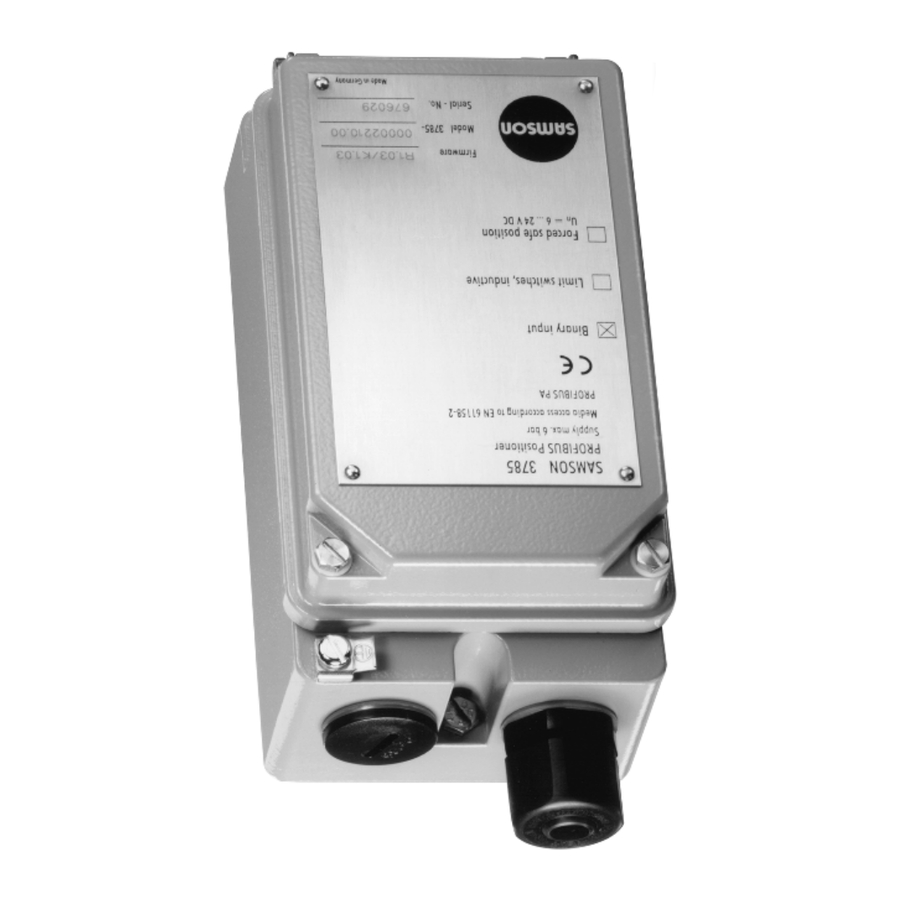
- Page 1 PROFIBUS Positioner Type 3785 PA device profile version 2.0 Fig. 1 ⋅ Type 3785 Mounting and operating instructions EB 8382-1 EN Firmware R 1.42/K 1.60 Edition January 2003...
-
Page 2: Table Of Contents
Contents Page Contents Design and principle of operation ..... . 8 Option ........8 Communication . - Page 3 Proper shipping and appropriate storage of the device are assumed. Note: Devices with the CE mark meet the requirements specified in the Direc- tive 94/9/EC and the Directive 89/336/EEC. The Declaration of Conformity can be viewed and downloaded on the Internet at www.samson.de. EB 8382-1 EN...
- Page 4 Firmware modifications Modifications of positioner firmware in comparison to previous version Obsolete Control R 1.23 R 1.31 Firmware adaptation for a new hardware version Hardware version device index .01 Control R 1.31 R 1.4 When the actuator type is set from "linear actuator" to Actuator type "rotary actuator", the following applies: Initialization method ....
- Page 5 The set point status BAD generally does not cause anymore the positioner to go to the fail-safe position, instead this behavior is determined by the FSAVE_TYPE parameter. The positioner can be set and operated using the SAMSON’s TROVIS-VIEW Configuration and Operator Interface over the serial interface.
- Page 6 Technical data Positioner Rated travel Adjustable Direct attachment Type 3277 7.5 to 30mm Attachment acc. to IEC 605347-6 7.5 to 120 mm (NAMUR) or 30° to 120° for rotary actuators Bus connection Fieldbus interface according to IEC 61158-2 Field device according to FISCO (Fieldbus intrinsically safe concept) Permissible operating voltage 9 to 32 V DC , power supply via the bus cable...
- Page 7 Data transmission according to PROFIBUS-PA, Profile Class B Version 2.0 acc. to EN 50170 and DIN 19245 Part 4 (Version 3.0 is also available) Local interface SAMSON SSP interface for configuration and start-up Bus address Adjustable over the software or microswitch; delivered status 126...
-
Page 8: Design And Principle Of Operation
Design and principle of operation ing to the reference variable. If there is no 1. Design and principle of operation system deviation, both the supply air and The digital PROFIBUS-PA positioner is de- the exhaust air valve are closed. signed for attachment to pneumatic control As a standard feature, the positioner is valves and is used to ensure a correspond- equipped with a binary input for floating... - Page 9 Design and principle of operation 31.25 kbit/s via twisted-pair cables accord- other actuators can only be carried out by ing to IEC 61158-2. means of communication. Positioners are generally adjusted by a per- Configuration sonal computer. One or more positioners are connected to the PC’s PROFIBUS seg- The positioner is configured and operated ment via segment coupler.
-
Page 10: Attaching The Positioner
2.1 Direct attachment to Type 3277 Actuator The positioner can be attached either di- rectly to a SAMSON Type 3277 Actuator, For the selection of the required mounting or according to NAMUR (IEC 60534-6), to parts, refer to tables 1, 2 and 3 on page control valves with casted yokes or rod-type yokes. - Page 11 Attaching the positioner Actuator stem retracts Actuator stem extends Internal signal pressure Signal pressure connection connection over piping Connection block Side view of connection Venting block with switch plate 1.2 Clamp Lever Lever Distance plate Cover Symbol "actuator stem extends" Marking Symbol "actuator stem retracts"...
- Page 12 Attaching the positioner 7. Mount the positioner so that the bore in 240, 350 and 700 cm Actuators the distance plate (15) is aligned with 6. Align the lateral switch plate at the con- the seal located in the bore of the actua- nection block (Fig.
- Page 13 Attaching the positioner Actuator size Mounting kit Table 1 Required lever with associated clamp and distance plate Order no. D1 (33 mm in length with clamp 17 mm in height) 120 (G1/4) 1400-6790 120 (NPT 1/4) 1400-6791 D1 (33 mm in length with clamp 17 mm in height) 240 and 350 1400-6370 D2 (44 mm in length with clamp 13 mm in height)
-
Page 14: Attachment Acc. To Iec 60534-6
Attaching the positioner Control valve with casted yoke 2.2 Attachment acc. to IEC 60534-6 1. Use countersunk screws to screw the For the selection of the required mounting plate (20) to the coupling which con- parts, refer to Tables 4 and 5 on page 17. nects the plug and actuator stem. - Page 15 Attaching the positioner Mounting position Attachment to NAMUR ribs Attachment to rods Levers N1, N2 Plate Clamp Clamping plate Screw Pointer Shaft Lever of positioner 27a Transmission pin 27b Lock nut Bracket Studs Plate Nuts Mounting bracket Fig. 4 ⋅ Attachment according to DIN IEC 60534-6 (NAMUR) EB 8382-1 EN...
-
Page 16: Presetting The Valve Travel
Attaching the positioner 2.2.2 Presetting the valve travel 1. Adjust the shaft (25) in the adapter housing so that the black pointer (24) is aligned with the casted marking on the adapter housing. 2. Screw clamping plate (22) tight in this position, using a screw (23). - Page 17 Attaching the positioner Control valve Travel in mm With lever Order no. Table 4 NAMUR attachment 7.5 to 60 N1 (125mm) 1400-6787 NAMUR mounting kit Valve with casted yoke 30 to 120 N2 (212 mm) 1400-6789 Parts, see Fig. 4 20 to 25 1400-6436 20 to 25...
-
Page 18: Attachment To Rotary Actuators
Actuators of other manufacturers: positioner, see chapter 2.3.4. 1. Position complete intermediate piece If the positioner is attached to a SAMSON (34, 42 and 44) on fixing level 1 of the Type 3278 Rotary Actuator, the air ex- bracket (VDI/VDE 3845) delivered with hausted from the positioner is admitted to the actuator and fasten with screws. - Page 19 Attaching the positioner Attachment to SAMSON Type 3278 Attachment according to VDI/VDE 3845 (NAMUR) 41 40 39 Positioner Venting over Intermediate piece filter check valve Lever with cam follower roll 0˚ Adapter Attachment with Transmission lever reversing amplifier Screws Scale...
-
Page 20: Aligning And Mounting The Cam Disk
Attaching the positioner 2.3.3 Aligning and mounting the In actuators with fail-safe position "Control cam disk valve open" (OPEN), the actuator must therefore be loaded with max. signal press- In rotary actuators with spring-return mech- ure prior to aligning the cam disk. anism, the built-in actuator springs deter- In springless actuators, the supply air must mine the fail-safe position and the direction... - Page 21 Control valve opens clockwise Control valve opens counterclockwise Fig. 6 ⋅ Aligning the cam disk Table 6 Rotary actuators (Complete mounting parts, but without cam disks) SAMSON Type 3278 Actuator Attachmt. acc. to VDI/VDE 3845 Attachment to Masoneilan actuator Actuator Actuator Camflex I...
-
Page 22: Reversing Amplifier For Rotary Actuators
Reversing amplifier for double-acting actuators Signal pressure connections 2.3.4 Reversing amplifier for double-acting actuators : Output A leading to the signal press- ure connection at the actuator which opens For the use with double-acting actuators, the valve when the pressure increases the positioner must be fitted with a revers- : Output A leading to the signal press-... - Page 23 Reversing amplifier for double-acting actuators From the positioner Output 38 Supply 9 Reversing amplifier Control signals 1.1 Special screws to the actuator 1.2 Gasket 1.3 Special nuts 1.4 Rubber seal 1.5 Plug 1.3 1.2 Fig. 7 ⋅ Mounting a reversing amplifier EB 8382-1 EN...
-
Page 24: Connections
Connections 3. Connections 3.1.1 Pressure gauge To monitor the positioner operation, it is 3.1 Pneumatic connections recommended that pressure gauges for sup- The air connections are either NPT 1/4 or ply air and signal pressure indication to the G 1/4 tapped holes. The customary fittings positioner be connected. -
Page 25: Supply Air Pressure
Connections 3.1.2 Supply air pressure 3.2 Electrical connections The required supply air pressure depends As far as the electrical installation of on the bench range and the operating direc- the device is concerned, the relevant tion (fail-safe action) of the actuator. The national regulations governing the bench range is indicated on the nameplate installation of electrical equipment... - Page 26 Connections Bus line Note on the selection of cables and wires: To run several intrinsically safe circuits in a The shielded PROFIBUS connecting cable multicore cable, note section 12 of EN must be routed over the EMC-proof brass 60079-14; VDE 0165/8.98. cable gland (standard) of the positioner to In particular, the radial thickness of commonly the terminals.
-
Page 27: Forced Venting
Connections For further information, refer to: 3.2.1 Forced venting PROFIBUS-PA User + Installation Guideline (PNO document 2.092). For positioners with forced venting function, a voltage of 6 to 24 V DC must be applied At the binary input, a passive floating con- to the relevant terminals. -
Page 28: Limit Switches
32 Volt). PROFIBUS guidelines. The TROVIS-VIEW software and the device If the positioner is used in hazardous areas, module 3785 in the 2.02 version are re- ex-proof versions of PROFIBUS-PA segment quired. couplers must be used. The positioner can also be accessed over... - Page 29 (Master Class 2) PROFIBUS-DP RS 485 Termination Non-haz- ardous Ex-proof segment coupler area Hazard- PROFIBUS-PA IEC 61158-2 ous area 3785-1 3785-1 3785-1 3785-1 Termination 10.2 Connection of Type 3785-1 Positioners in hazardous areas Fig. 10 ⋅ PROFIBUS connection EB 8382-1 EN...
-
Page 30: Operation
Operation 4. Operation 4.1 LED controls Two LEDs located inside the cover serve to WARNING monitor the positioner, indicating the posi- Before you take the positioner into tioner’s status during maintenance proce- operation, carefully move the control dures, operation and in the event of defects. valve to its end position by covering The colors generally indicate the following: the hole (manually) on the cover plate... -
Page 31: Write Protection
Operation 3. Set switch to desired position: 4.2 Write protection 1 ENABLED > Function activated A microswitch marked "write protection" is 2 DISABLED > Function deactivated. located to the right of the seven bus address 4.4 Default setting selector switches inside the hinged cover. When it is activated (position ON), the posi- All parameters are set to default values. -
Page 32: Adjusting Mechanical Zero
Operation during the start-up cycle when the 4.4.1 Adjusting mechanical zero shut-off valves in the plant are closed, or when the control valve NOTE with the positioner has been Zero must be adjusted with the valve closed. removed from the plant and is used (For three-way valves with the actuator stem on a test stand. - Page 33 Operation Set delay time to 30 s at the minimum. Electric zero calibration Enter tag identification. If, during the valve’s operation, the mechan- If necessary, other configuration, e.g. ical zero has shifted, an electric zero cali- special characteristics for rotary valves. bration can be carried out.
-
Page 34: Adjusting The Inductive Limit Switches
Operation Adjusting the switching point: 4.5 Adjusting the inductive limit The limit switches are marked GW1 and switches GW2 on the inside of the case cover. Yel- low tags and the associated adjustment The positioner version with inductive limit screws (Fig. 11) are located below these switches has two adjustable tags that are markings. -
Page 35: Maintenance
Maintenance 5. Maintenance 6. Servicing ex-proof versions The positioner is maintenance free. In the event that a positioner’s part on Pneumatic connection 9/Supply contains a which the explosion protection is based filter with a mesh size of 100 µm. If re- must be serviced, the positioner must not be quired, the filter can be unscrewed and taken into operation again, unless an ex-... -
Page 36: How To Implement The Profibus Master Class 1
The device database files are provided as a text file SAMS3785.GSD. They are available at SAMSON AG under Product no. 1400-7417 on a 1.44 MB disk 3 1/2". Or you can down- load the files via Internet from the following sites: http://www.samson.de or http: //www.profibus.com. - Page 37 How to implement the PROFIBUS Master Class 1 Output value (Output) Byte 0 Octet 1 Octet 2 Octet 3 Octet 4 Octet 5 Sign, Exponent, Exponent Fraction Fraction Fraction RCAS_IN, Value Status (Floating Point, IEEE) Variant 3: Module = " READBACK + POS_D, SP " 0x96, 0xA4 Input value (Input) Byte 0 Octet 1...
- Page 38 How to implement the PROFIBUS Master Class 1 Output value (Output) Byte 0 Octet 1 Octet 2 Octet 3 Octet 4 Octet 5 Sign, Exponent, Exponent Fraction Fraction Fraction SP, Value Status (Floating Point, IEEE) Variant 5: Module = " READBACK + POS_D + CHECKBACK, SP " 0x99, 0xA4 Input value (Input) Byte 0 Octet 1...
- Page 39 How to implement the PROFIBUS Master Class 1 Output value (Output) Byte 0 Octet 1 Octet 2 Octet 3 Octet 4 Octet 5 Sign, Exponent, Exponent Fraction Fraction Fraction SP, Value Status (Floating Point, IEEE) Variant 7: Module = " READBACK+ RCAS_OUT+ POS_D+ CHECKBACK, SP+ RCAS_IN " 0x9E, 0xA9 Input value (Input) Byte 0 Octet 1...
-
Page 40: Parameter Description
How to implement the PROFIBUS Master Class 1 7.3 Parameter description SP - Set point with status: Reference variable w in "Auto" operating mode The reference variable w of the positioner is preset via SP in automatic mode ("Auto"). SP consists of a floating point value (4 bytes) and the associated status (1 byte). Value and status must be transferred together (data consistency = 5 bytes). - Page 41 8, 9 Not used CB_UPDATE_EVT This message is issued when device data are changed CB_SIMULATE Simulation mode, i.e. values are not derived from the process CB_DISTURBANCE Error, see DIAGNOSIS parameter for cause CB_CONTR_ERR Internal positioner control loop error (must be confirmed via Class 2 Master).
-
Page 42: Status Code Of The Measuring Value
How to implement the PROFIBUS Master Class 1 7.4 Status code of the measured value The following status codes (decimal values) are used by the Type 3785 Positioner: BAD: non-specific – value bad without more details. Configuration Error – device settings not consistent. -
Page 43: Operating Modes
Manual (Man) Remote Cascade (RCas) Local Override (LO) Out of Service (OS) The Type 3785 Positioner supports the following operating modes: up to firmware version K 1.20: OS, AUTO firmware version K 1.30 and higher: OS, LO, MAN, AUTO Automatic (Auto) - Page 44 How to implement the PROFIBUS Master Class 1 Operating mode during start-up (warmstart) The response of the positioner to the warmstart is determined by the parameter FSAFE_TYPE (fail-safe action). If FSAFE_TYPE is set to "adjust to fail-safe value", the positioner switches to automatic opera- ting mode and adjusts to the value determined by the parameter FSAFE_VALUE.
- Page 45 End position function EB 8382-1 EN...
-
Page 46: List Of Parameters
The list of parameters following the overview is in alphabetical order and describes all posi- tioner parameters that can be displayed or modified via PROFIBUS communication, e.g. on a PC. Manufacturer-specific parameters of the SAMSON Type 3785 PROFIBUS-PA Positioner have been marked with (M). Parameter overview: Device identification Loop/tag identification . - Page 47 List of parameters Start-up Security locking ......SECURITY_LOCKING Coldstart ....... . . FACTORY_RESET Warmstart .
- Page 48 List of parameters End position when reference variable is below limit value SETP_CUTOFF_DEC End position when reference variable is above limit value SETP_CUTOFF_INC Characteristic selection ..... . . CHARACT Characteristic type .
- Page 49 For rotary actuators, only attachment according to VDI / VDE 3845 (NAMUR) is possible. For more details on attachments, see also Chapters 2.1 and 2.2. States: 0 = Integral — attachment in combination with a SAMSON Type 3277 Linear Actuator 1 = NAMUR — attachment according to DIN/IEC 534 (NAMUR) Default:...
- Page 50 2 = Equal percentage reverse 3 = Customized (supported by a future Firmware version) 4 = SAMSON butterfly control valve: linear 5 = SAMSON butterfly control valve: equal percentage 6 = Vetec rotary plug valve: linear 7 = Vetec rotary plug valve: equal percentage...
- Page 51 List of parameters Indicates the last maintenance date of the field device. Date last maintenance VALVE_MAINT_DATE Date of installation Indicates the date on which the field device was installed. DEVICE_INSTALL_DATE Dead band of the control characteristic Dead band Xtot DEAD_BAND in the range of 0.1 to 10.0 % of the rated travel/nominal angle Default: 0.5 %...
-
Page 52: End Position When Reference Variable Is Below Limit Value Setp_Cutoff_Dec
List of parameters Additional manufacturer-specific detailed device information, coded bit-wise Diagnosis extension DIAGNOSIS_EXTENSION encoded which enables several simultaneous messages, see also Chapter 9. Message type: A: Dynamic messages; they are automatically reset by readout. R: Static messages; they are retained, as long as the event is imminent in the field device. States: 0: No message 1: Message active... - Page 53 List of parameters Substitute value for set point (reference variable w or w_rcas) when communication Fail-safe value reference variable FSAFE_VALUE failure is recognized. Default: Firmware version communication/control Firmware version SW_REVISION Hardware version Hardware version electronics/mechanics HW_REVISION Identification forced venting Indicates whether the optional forced venting function has been installed. IDENT_FORCED_VENTING (M) Read-only parameter (automatically set by the device) States:...
-
Page 54: Operating Mode, Required/Valid
List of parameters Positioner operating mode. Operating mode, required/valid Up to Firmware Version K 1.20: OS, AUTO MODE_BLK/TARGET-MODE Firmware Version K 1.30 and higher: OS, LO, MAN, AUTO Positioner operating modes: Automatic (AUTO): In this operating mode, the positioner follows the cyclic or acyclic set point entered via the parameter SP (w) according to the scale and unit entered via PV_SCALE (reference variable range). - Page 55 List of parameters If the status of the transmitted set point is "bad" (value < 64) or the positioner has not been successfully initialized, it remains in fail-safe position (out of service). The action determined by the parameter FSAFE_TYPE (fail-safe action) is caused by the following events: Start-up of the positioner (warmstart).
-
Page 56: Reference Variable W
List of parameters Type of Rated travel/ Transit time KP_Y1 KP_Y2 actuator nom. angle Supply air Exhaust air min. Spring action Open Closed > 0.7 s > 0.7 s 0.12 Closing > 0.7 s < 0.7 s 0.12 Rotary actuator Closing <... -
Page 57: Transducer State
List of parameters Serial number of the positioner. Serial no. positioner DEVICE_SER_NUM Uniquely identifies the field device in combination with the manufacturer’s name and the device type number. Serial number of the positioner’s corresponding valve. Serial no. valve VALVE_SER_NUM Length: 16 characters Set point deviation e System deviation in % SETP_DEVIATION... - Page 58 List of parameters The min. transit time CLOSED (in direction of the 0 % position) is the actual time in seconds Transit time minimum CLOSED required by the system comprising positioner, actuator and valve to pass through the rated ACT_STROKE_TIME_DEC travel/nominal angle in direction of the valve to be closed (measured during start-up).
-
Page 59: Valve Travel, Total
List of parameters Lower and upper adjustment value of the effective working range in [mm] or [degree]. Travel /angle of rotation range OUT_SCALE For a non-linear characteristic, the characteristic is adapted to the reduced travel. For initialization in the maximum range, the travel/angle of rotation range is always related to the rated travel/angle entered. -
Page 60: Messages And Diagnosis
Messages and diagnosis 9. Messages and diagnosis During the initialization phase, the Type 3785 PROFIBUS-PA Positioner provides the best possibilities for diagnosis. In the automatic mode, detailed tests are carried out to check the attachment and the positioner’s reaction while taking the preset or entered data into account. - Page 61 Messages and diagnosis Auto initialization error Initialization was not successful. For detailed error messages, see chapter 9.4. Automatic reset after initialization has been successfully completed. Zero point error (final pos.) This message indicates any changes exceeding the value determined during the initialization or zero adjustment by more than ±5 %.
-
Page 62: Diagnosis Extension Messages
Messages and diagnosis Characteristic invalid This message is generated if one of the following applies: - Errors are recognized during transmission of the characteristic to the device. - For a user-defined characteristic, the input values were not entered in ascending order. - For the user-defined characteristic an inclination value >16 was entered. -
Page 63: Check-Back" Messages
Messages and diagnosis 9.3 "CHECK-BACK" messages Fail-safe position (MODE = OUT OF SERVICE) The fail-safe position was activated by the device and can be caused by selecting operating mode "OUT OF SERVICE", by activating the forced venting option or by communication failure. - Page 64 Messages and diagnosis Control loop error This message is displayed when the positioner fails to control the adjusted range of tolerance for error messages within the preset delay time. Possible sources of error: – Oscillation caused by actuator operated too fast (small travel volume) Remedy: Reduce supply air pressure as per chapter 3.1.2 or install a signal pressure throttle.
-
Page 65: Initialization Messages
Messages and diagnosis 9.4 Initialization messages Not defined The device has not been initialized, or a coldstart was carried out. Automatic reset after confirmation. Aborted The initialization routine was aborted by the user. Automatic reset after acknowledgement. If the device was already successfully initialized and no coldstart was performed, control operation restarts. - Page 66 Messages and diagnosis – Incorrect mechanical attachment – Incorrect transmission entered – For NAMUR attachment: wrong pin position entered – Valve is blocked – Supply pressure too low. The supply pressure should be minimum 0.4 bar above the upper spring range value (see chapter 3.1.2). Air leakage of pneumatic system The actuator stalls for a few seconds when the duty cycle is being determined initially.
- Page 67 Messages and diagnosis Proportional band restricted too much Even the smallest permissible pulses still cause too large changes in travel. Initialization is aborted. Possible sources of error: – Supply pressure too high – Missing signal pressure throttle for actuators with small volumes –...
-
Page 68: Dimensional Drawing
Dimensional diagram Pneumatic connections G 1/4 or NPT 1/4 M20 x1.5 (formerly PG 13.5) Output (38 30.5 Supply (9) Reversing amplifier (optional) Fulcrum of Attachment with intermediate the driving shaft piece for rotary actuators Attachment IEC 60534-6 w. adapter housing Output 1 (A1) 28.5 Output 2 (A2) -
Page 69: Certificates
EB 8382-1 EN... - Page 70 EB 8382-1 EN...
- Page 71 EB 8382-1 EN...
- Page 72 EB 8382-1 EN...
- Page 73 EB 8382-1 EN...
- Page 74 EB 8382-1 EN...
- Page 75 EB 8382-1 EN...
- Page 76 EB 8382-1 EN...
- Page 77 EB 8382-1 EN...
- Page 78 EB 8382-1 EN...
- Page 79 EB 8382-1 EN...
- Page 80 SAMSON AG ⋅ MESS- UND REGELTECHNIK Weismüllerstraße 3 ⋅ 60314 Frankfurt am Main ⋅ Germany Phone +49 69 4009-0 ⋅ Fax +49 69 4009-1507 EB 8382-1 EN Internet: http://www.samson.de...
Need help?
Do you have a question about the 3785 and is the answer not in the manual?
Questions and answers