Table of Contents
Advertisement
Quick Links
Advertisement
Table of Contents

Related Manuals for Supero 4042G-72RF4


Summary of Contents for Supero 4042G-72RF4
- Page 1 UPER ® A+ SERVER 4042G-72RF4 USER’S MANUAL Revision 1.0b...
- Page 2 The information in this User’s Manual has been carefully reviewed and is believed to be accurate. The vendor assumes no responsibility for any inaccuracies that may be contained in this document, makes no commitment to update or to keep current the information in this manual, or to notify any person or organization of the updates.
-
Page 3: About This Manual
About This Manual This manual is written for professional system integrators and PC technicians. It provides information for the installation and use of the A+ Server 4042G-72RF4. Installation and maintenance should be performed by experienced technicians only. The A+ Server 4042G-72RF4 is a high-end server based on the SC748TQ-R1K43B chassis and the H8QG7-LN4F, a high-end serverboard which is based on the AMD®... - Page 4 A+ SERVER 4042G-72RF4 USER'S MANUAL Chapter 6: Advanced Chassis Setup Refer to Chapter 6 for detailed information on the SC748TQ-R1K43B server chassis. You should follow the procedures given in this chapter when installing, removing or reconfiguring SCSI/SATA or peripheral drives and when replacing system power supply units and cooling fans.
-
Page 5: Table Of Contents
Preface Contents Chapter 1 Introduction Overview ......................1-1 Serverboard Features ..................1-2 Processors ...................... 1-2 Memory ......................1-2 SAS ......................... 1-2 Serial ATA ......................1-3 PCI Expansion Slots ..................1-3 Ethernet Ports ....................1-3 Onboard Controllers/Ports ................1-3 Graphics Controller ..................1-3 IPMI ......................... - Page 6 A+ SERVER 4042G-72RF4 USER'S MANUAL Installing the System into a Rack ..............2-4 Identifying the Sections of the Rack Rails ............2-4 Installing the Chassis Rails ................2-5 Installing the Rack Rails ................. 2-6 Installing the Server into the Rack ..............2-7 Checking the Serverboard Setup ..............
- Page 7 Preface Processor and Heatsink Installation..............5-4 Installing a Passive CPU Heatsink ..............5-6 Installing Memory .................... 5-7 DIMM Module Population Configuration ............ 5-9 Serverboard Details ..................5-10 H8QG7-LN4F Quick Reference ..............5-10 Connector Definitions ................... 5-13 Jumper Settings .................... 5-21 Explanation of Jumpers ................
- Page 8 A+ SERVER 4042G-72RF4 USER'S MANUAL Chapter 7 BIOS Introduction ...................... 7-1 Main Menu ...................... 7-2 Advanced Settings Menu ................7-3 Security Settings Menu ................. 7-16 Boot Settings Menu ..................7-16 Exit Menu ...................... 7-18 Appendix A BIOS Error Beep Codes...
-
Page 9: Chapter 1 Introduction
Chapter 1 Introduction Overview The A+ Server 4042G-72RF4 is a high-end server that is comprised of two main subsystems: the SC748TQ-R1K43B 4U/tower server chassis and the H8QG7-LN4F serverboard. Please refer to our web site for information on operating systems that have been certified for use with the A+ Server 4042G-72RF4 (www. -
Page 10: Serverboard Features
For support, email support@supermicro.com. Serverboard Features At the heart of the A+ Server 4042G-72RF4 is one H8QG7-LN4F quad processor serverboard, which is based on the SR5690/SR5670/SP5100 chipset. Shown below are the main features of the serverboard. Processors The H8QG7-LN4F supports four AMD Opteron 6000 series (AMD Socket G34 type) processors. -
Page 11: Serial Ata
Chapter 1: Introduction Serial ATA The South Bridge (SP5100) of the chipset includes a Serial ATA controller for six 3 Gb/s SATA drives. The hot-swappable SATA drives are connected to a backplane that provides power, bus termination and configuration settings. RAID 0, 1 and 10 are supported. -
Page 12: System Block Diagram
A+ SERVER 4042G-72RF4 USER'S MANUAL Figure 1-1. AMD SR5690/SR5670/SP5100 Chipset: System Block Diagram Note: This is a general block diagram. Please see Chapter 5 for details. CH 1A, 1B, 2A, 2B, 3A, 3B, 4A, 4B CH 1A, 1B, 2A, 2B, 3A, 3B, 4A, 4B... -
Page 13: Server Chassis Features
SAS/SATA hard drives. Front Control Panel The control panel on the A+ Server 4042G-72RF4 provides you with system monitoring and control. LEDs indicate system power, HDD activity, network activity, system overheat and power supply failure. A main power button and a system reset button are also included. -
Page 14: Contacting Supermicro
A+ SERVER 4042G-72RF4 USER'S MANUAL Contacting Supermicro Headquarters Address: Super Micro Computer, Inc. 980 Rock Ave. San Jose, CA 95131 U.S.A. Tel: +1 (408) 503-8000 Fax: +1 (408) 503-8008 Email: marketing@supermicro.com (General Information) support@supermicro.com (Technical Support) Web Site: www.supermicro.com Europe Address: Super Micro Computer B.V. -
Page 15: Chapter 2 Server Installation
If the server itself shows damage you should file a damage claim with the carrier who delivered it. Decide on a suitable location for the 4042G-72RF4. It should be situated in a clean, dust-free area that is well ventilated. Avoid areas where heat, electrical noise and electromagnetic fields are generated. -
Page 16: Choosing A Setup Location
A+ SERVER 4042G-72RF4 USER'S MANUAL Choosing a Setup Location • Leave enough clearance in front of the system to enable you to open the front door completely (~25 inches). • Leave approximately 30 inches of clearance in the back of the system to allow for sufficient airflow and ease in servicing. -
Page 17: Rack Mounting Considerations
Chapter 2: Server Installation Rack Mounting Considerations Warning! To prevent bodily injury when mounting or servicing this unit in a rack, you must take special precautions to ensure that the system remains stable. The following guidelines are provided to ensure your safety: •... -
Page 18: Installing The System Into A Rack
A+ SERVER 4042G-72RF4 USER'S MANUAL Installing the System into a Rack This section provides information on installing the system into a rack unit. Rack installation requires the use of the optional rackmount kit. There are a variety of rack units on the market, so the procedure may differ slightly. Also refer to the installation instructions that came with the rack unit you are using. -
Page 19: Installing The Chassis Rails
Chapter 2: Server Installation Installing the Chassis Rails Remove the top bezel cover and the feet to add rack rails to the chassis. Orient the chassis in the rackmount position, as in the figure below. 1. Remove the top and right covers by depressing the latch on the rear lip of the top cover to release it, then push the cover off. -
Page 20: Installing The Rack Rails
A+ SERVER 4042G-72RF4 USER'S MANUAL Figure 2-3. Installing the Rails to the Chassis Installing the Rack Rails Stability hazard. The rack stabilizing mechanism must be in place, or the rack must be bolted to the floor before you slide the unit out for servicing. Failure to stabilize the rack can cause the rack to tip over. -
Page 21: Installing The Server Into The Rack
Chapter 2: Server Installation Installing the Server into the Rack Rails are attached to both the chassis and the rack unit. The next step is to install the chassis into the rack. Find the two brackets in the rack mount kit. Install these, keeping in mind that they are left and right specific (marked with "L"... -
Page 22: Checking The Serverboard Setup
A+ SERVER 4042G-72RF4 USER'S MANUAL Checking the Serverboard Setup After setting up the the system, open the unit to make sure the serverboard is properly installed and all the connections have been made (see Figure 2-5). Accessing the Inside of the System 1. - Page 23 Chapter 2: Server Installation Figure 2-5. Accessing the Inside of the System...
-
Page 24: Checking The Drive Bay Setup
A+ SERVER 4042G-72RF4 USER'S MANUAL Checking the Drive Bay Setup Next, you should check to make sure the peripheral drives and the SCSI drives and backplane have been properly installed and all connections have been made. Checking the Drive Bay Setup •... -
Page 25: Chapter 3 System Interface
Chapter 3: System Interface Chapter 3 System Interface Overview Several buttons and LEDs on the control panel that indicate the status of the system. There are also LEDs on the drive carriers that indicate the status of the drive. There is an on/off switch on the power supply. -
Page 26: Control Panel Buttons
A+ SERVER 4042G-72RF4 USER'S MANUAL Control Panel Buttons There are two push-buttons located on the front of the chassis: a reset button and a power on/off button. Reset: Use the reset button to reboot the system. Power: The main power button is used to apply or remove power to the server system from the power supply. -
Page 27: Informational Led
Chapter 3: System Interface Alert: The Informational LED signals status alerts. Informational LED State Description An overheat condition has occured. Continuously on and red (This may be caused by cable congestion). Blinking red (1Hz) Fan failure, check for an inoperative fan. Blinking red (0.25Hz) Power failure, check for a non-operational power supply. -
Page 28: Sas Drive Carrier Leds
A+ SERVER 4042G-72RF4 USER'S MANUAL SAS Drive Carrier LEDs Each SAS drive carrier has two LEDs: • Green: When illuminated, the green LED on the front of the SAS drive carrier indicates drive activity. A connection to the backplane enables this LED to blink on and off when that particular drive is being accessed. -
Page 29: About Standardized Warning Statements
Chapter 4: Warning Statements for AC Systems Chapter 4 Standardized Warning Statements for AC Systems About Standardized Warning Statements The following statements are industry standard warnings, provided to warn the user of situations which have the potential for bodily injury. Should you have questions or experience difficulty, contact Supermicro's Technical Support department for assistance. - Page 30 A+ SERVER 4042G-72RF4 USER'S MANUAL Warnung WICHTIGE SICHERHEITSHINWEISE Dieses Warnsymbol bedeutet Gefahr. Sie befinden sich in einer Situation, die zu Verletzungen führen kann. Machen Sie sich vor der Arbeit mit Geräten mit den Gefahren elektrischer Schaltungen und den üblichen Verfahren zur Vorbeugung vor Unfällen vertraut.
- Page 31 Warning Statements for AC Systems جسذٌة اصابة ًتتسبب ف حالة ٌوكي أى ًاًك ف خطز ًٌٌع هذا الزهز !تحذٌز الذوائز بالوخاطز الٌاجوة عي ي على علن ، ك هعذات تعول على أي قبل أى الكهزبائٍة حىادث أي وقىع وٌع ل الىقائٍة...
-
Page 32: Installation Instructions
A+ SERVER 4042G-72RF4 USER'S MANUAL Installation Instructions Warning! Read the installation instructions before connecting the system to the power source. 設置手順書 システムを電源に接続する前に、 設置手順書をお読み下さい。 警告 将此系统连接电源前,请先阅读安装说明。 警告 將系統與電源連接前,請先閱讀安裝說明。 Warnung Vor dem Anschließen des Systems an die Stromquelle die Installationsanweisungen lesen. ¡Advertencia! Lea las instrucciones de instalación antes de conectar el sistema a la red de... -
Page 33: Circuit Breaker
Chapter 4: Warning Statements for AC Systems Circuit Breaker Warning! This product relies on the building's installation for short-circuit (overcurrent) protection. Ensure that the protective device is rated not greater than: 250 V, 20 A. サーキッ ト ・ ブレーカー この製品は、 短絡 (過電流) 保護装置がある建物での設置を前提としています。 保護装置の定格が250 V、... -
Page 34: Power Disconnection Warning
A+ SERVER 4042G-72RF4 USER'S MANUAL في التي تم تثبيتها مه الدوائرالقصيرة الحمايت معداث يعتمد على هذا المنتج المبنى أكثر من ليس وقائي ال الجهاز تقييم أن تأكد من 20A, 250V 경고! 이 제품은 전원의 단락(과전류)방지에 대해서 전적으로 건물의 관련 설비에... - Page 35 Chapter 4: Warning Statements for AC Systems Warnung Das System muss von allen Quellen der Energie und vom Netzanschlusskabel getrennt sein, das von den Spg.Versorgungsteilmodulen entfernt wird, bevor es auf den Chassisinnenraum zurückgreift, um Systemsbestandteile anzubringen oder zu entfernen. ¡Advertencia! El sistema debe ser disconnected de todas las fuentes de energía y del cable eléctrico quitado de los módulos de fuente de alimentación antes de tener acceso el interior del chasis para instalar o para quitar componentes de sistema.
-
Page 36: Equipment Installation
A+ SERVER 4042G-72RF4 USER'S MANUAL Equipment Installation Warning! Only trained and qualified personnel should be allowed to install, replace, or service this equipment. 機器の設置 トレーニングを受け認定された人だけがこの装置の設置、 交換、 またはサービスを許可 されています。 警告 只有经过培训且具有资格的人员才能进行此设备的安装、更换和维修。 警告 只有經過受訓且具資格人員才可安裝、更換與維修此設備。 Warnung Das Installieren, Ersetzen oder Bedienen dieser Ausrüstung sollte nur geschultem, qualifiziertem Personal gestattet werden. -
Page 37: Restricted Area
Chapter 4: Warning Statements for AC Systems Waarschuwing Deze apparatuur mag alleen worden geïnstalleerd, vervangen of hersteld door geschoold en gekwalificeerd personeel. Restricted Area Warning! This unit is intended for installation in restricted access areas. A restricted access area can be accessed only through the use of a special tool, lock and key, or other means of security. -
Page 38: Battery Handling
A+ SERVER 4042G-72RF4 USER'S MANUAL אזור עם גישה מוגבלת !אזהרה יש להתקין את היחידה באזורים שיש בהם הגבלת גישה. הגישה ניתנת בעזרת .)'כלי אבטחה בלבד (מפתח, מנעול וכד محظورة مناطق ٍنتركُبها ف هذه انىحذة تخصيص تم ،أداة خاصت من خالل استخذاو... - Page 39 Chapter 4: Warning Statements for AC Systems Warnung Bei Einsetzen einer falschen Batterie besteht Explosionsgefahr. Ersetzen Sie die Batterie nur durch den gleichen oder vom Hersteller empfohlenen Batterietyp. Entsorgen Sie die benutzten Batterien nach den Anweisungen des Herstellers. Attention Danger d'explosion si la pile n'est pas remplacée correctement. Ne la remplacer que par une pile de type semblable ou équivalent, recommandée par le fabricant.
-
Page 40: Redundant Power Supplies
A+ SERVER 4042G-72RF4 USER'S MANUAL Redundant Power Supplies Warning! This unit might have more than one power supply connection. All connections must be removed to de-energize the unit. 冗長電源装置 このユニッ トは複数の電源装置が接続されている場合があります。 ユニッ トの電源を切るためには、 すべての接続を取り外さなければなりません。 警告 此部件连接的电源可能不止一个,必须将所有电源断开才能停止给该部件供电。 警告 此裝置連接的電源可能不只一個,必須切斷所有電源才能停止對該裝置的供電。 Warnung Dieses Gerät kann mehr als eine Stromzufuhr haben. Um sicherzustellen, dass der Einheit kein trom zugeführt wird, müssen alle Verbindungen entfernt werden. -
Page 41: Backplane Voltage
Chapter 4: Warning Statements for AC Systems امداد الطاقة بوحدات عدة اتصاالت جهاز ال يكون لهذا قد الكهرباء عن وحدة ال لعسل كافة االتصاالت يجب إزالة 경고! 이 장치에는 한 개 이상의 전원 공급 단자가 연결되어 있을 수 있습니다. 이 장치에 전원을... -
Page 42: Comply With Local And National Electrical Codes
A+ SERVER 4042G-72RF4 USER'S MANUAL Attention Lorsque le système est en fonctionnement, des tensions électriques circulent sur le fond de panier. Prendre des précautions lors de la maintenance. מתח בפנל האחורי !הרה אז קיימת סכנת מתח בפנל האחורי בזמן תפעול המערכת. יש להיזהר במהלך... -
Page 43: Product Disposal
Chapter 4: Warning Statements for AC Systems ¡Advertencia! La instalacion del equipo debe cumplir con las normas de electricidad locales y nacionales.Attention L'équipement doit être installé conformément aux normes électriques nationales et locales. תיאום חוקי החשמל הארצי !אזהרה הציוד חייבת להיות תואמת לחוקי החשמל המקומיים והארציים התקנת... -
Page 44: Hot Swap Fan Warning
A+ SERVER 4042G-72RF4 USER'S MANUAL Warnung Die Entsorgung dieses Produkts sollte gemäß allen Bestimmungen und Gesetzen des Landes erfolgen. ¡Advertencia! Al deshacerse por completo de este producto debe seguir todas las leyes y reglamentos nacionales. Attention La mise au rebut ou le recyclage de ce produit sont généralement soumis à des lois et/ou directives de respect de l'environnement. - Page 45 Chapter 4: Warning Statements for AC Systems 当您从机架移除风扇装置,风扇可能仍在转动。小心不要将手指、螺丝起子和其他 物品太靠近风扇 警告 當您從機架移除風扇裝置,風扇可能仍在轉動。小心不要將手指、螺絲起子和其他 物品太靠近風扇。 Warnung Die Lüfter drehen sich u. U. noch, wenn die Lüfterbaugruppe aus dem Chassis genommen wird. Halten Sie Finger, Schraubendreher und andere Gegenstände von den Öffnungen des Lüftergehäuses entfernt. ¡Advertencia! Los ventiladores podran dar vuelta cuando usted quite ell montaje del ventilador del chasis.
-
Page 46: Power Cable And Ac Adapter
A+ SERVER 4042G-72RF4 USER'S MANUAL Waarschuwing Het is mogelijk dat de ventilator nog draait tijdens het verwijderen van het ventilatorsamenstel uit het chassis. Houd uw vingers, schroevendraaiers en eventuele andere voorwerpen uit de buurt van de openingen in de ventilatorbehuizing. - Page 47 Chapter 4: Warning Statements for AC Systems ¡Advertencia! Al instalar el producto, utilice los cables de conexión previstos o designados, los cables y adaptadores de CA. La utilización de otros cables y adaptadores podría ocasionar un mal funcionamiento o un incendio. Aparatos Eléctricos y la Ley de Seguridad del Material prohíbe el uso de UL o CSA cables certificados que tienen UL o CSA se muestra en el código de otros dispositivos eléctricos que los productos designados por Supermicro solamente.
- Page 48 A+ SERVER 4042G-72RF4 USER'S MANUAL Waarschuwing Bij het installeren van het product, gebruik de meegeleverde of aangewezen kabels, stroomkabels en adapters. Het gebruik van andere kabels en adapters kan leiden tot een storing of een brand. Elektrisch apparaat en veiligheidsinformatiebladen wet...
-
Page 49: Chapter 5 Advanced Serverboard Setup
Chapter 5: Advanced Serverboard Setup Chapter 5 Advanced Serverboard Setup The H8QG7-LN4F serverboard comes installed. This chapter describes procedures for installation of processors and heatsinks, memory, and extension (add-on) cards. Serverboard cables, jumpers and connections are also described. A layout and quick reference chart are included for your reference. -
Page 50: Connecting Cables
A+ SERVER 4042G-72RF4 USER'S MANUAL Connecting Cables Necessary cables include the data (ribbon) cables for the peripherals and control panel and the power cables. Connecting Data Cables The ribbon cables used to transfer data from the peripheral devices have been carefully routed to prevent them from blocking the flow of cooling air that moves through the system from front to back. -
Page 51: I/O Ports
Chapter 5: Advanced Serverboard Setup Figure 5-1. Control Panel Header Pins 20 19 Ground No Connection Power LED 3.3V HDD LED FP UID Switch/3.3VSB NIC1 (Link) LED NIC1 (Activity) LED NIC2 (Link) LED NIC2 (Activity) LED OH/Fan Fail/PWR Fail/UID LED Blue_LED_Cathode (UID)/5V SB Power Fail LED 3.3V... -
Page 52: Processor And Heatsink Installation
A+ SERVER 4042G-72RF4 USER'S MANUAL Processor and Heatsink Installation Caution: When handling the processor, avoid placing direct pressure on the label area of the fan. Also, do not place the serverboard on a conductive surface, which can damage the BIOS battery and prevent the system from booting up. - Page 53 Chapter 5: Advanced Serverboard Setup 3. Use your thumb and your index finger to hold the CPU. Locate and align pin 1 of the CPU socket with pin 1 of the CPU. Both are marked with a triangle. Triangle 4. Align pin 1 of the CPU with pin 1 of the socket.
-
Page 54: Installing A Passive Cpu Heatsink
A+ SERVER 4042G-72RF4 USER'S MANUAL Installing a Passive CPU Heatsink 1. Do not apply any thermal grease to the heatsink or the CPU die -- the required amount has already been applied. 2. Place the heatsink directly on top of the CPU so that the heat sink screws are aligned with the mounting holes on the back plate. -
Page 55: Installing Memory
Chapter 5: Advanced Serverboard Setup Installing Memory Caution: Exercise extreme caution when installing or removing memory modules to prevent any possible damage. Installing Memory 1. Insert each memory module vertically into its slot, paying attention to the notch along the bottom of the module to prevent inserting the module incorrectly (see Figure 2-1). - Page 56 A+ SERVER 4042G-72RF4 USER'S MANUAL Figure 5-4. Installing DIMM into Slot To Install: Insert Notch Notch module vertically and press down until it snaps into place. Front View Pay attention to the alignment notch at the bottom. Note: Notch should align with...
-
Page 57: Dimm Module Population Configuration
Chapter 5: Advanced Serverboard Setup DIMM Module Population Configuration For memory to work properly, follow the tables below for memory installation: Per Channel DIMM Populations Options DIMM Type DIMM A DIMM B Max. MHz, Max. MHz, Max. GB/ 1.5V DIMMs 1.35V DIMMs Channel SR or DR... -
Page 58: Serverboard Details
A+ SERVER 4042G-72RF4 USER'S MANUAL Serverboard Details H8QG7-LN4F Quick Reference Jumper Description Default Setting JBT1 CMOS Clear (See Section 5-8) JI2C1/JI2C2 I2C to PCI-E Slot Enable/Disable Pin 2-3 (Disabled) JPB1 BMC Enable/Disable Pins 1-2 (Enabled) JPG1 VGA Enable/Disable Pins 1-2 (Enabled) - Page 59 Chapter 5: Advanced Serverboard Setup Connector Description COM1 COM1 Serial Header FAN 1-9 Chassis/CPU Fan Headers IPMI LAN Dedicated IPMI LAN Port Speaker Header Front Panel Connector NIC3/NIC4 (LAN3/4) LED Connectors JIPMB1 System Management Bus Header (SMBus) Chassis Intrusion Header JOH1 Overheat Warning Header JPI2C1...
- Page 60 A+ SERVER 4042G-72RF4 USER'S MANUAL Figure 5-5. H8QG7-LN4F Layout (not drawn to scale) FAN9 FAN8 FAN7 UID/LE1 /CPU1 /CPU3 Intel I350 CPU1 CPU3 BATTERY SP5100 SR5690 CPU2 CPU4 SR5670 2208 SAS2 JPW4 JPW3 JPW2 JPW1 SPEAKER Notes: Jumpers not indicated are for test purposes only.
-
Page 61: Connector Definitions
Chapter 5: Advanced Serverboard Setup Connector Definitions ATX Power 24-pin Connector Pin Definitions Power Connectors Pin# Definition Pin # Definition A 24-pin main power supply connector(JPW1) +3.3V +3.3V and three 8-pin CPU PWR connectors -12V +3.3V (JPW2/JPW3/JPW4) on the motherboard. These power connectors meet the SSI EPS PS_ON 12V specification. - Page 62 A+ SERVER 4042G-72RF4 USER'S MANUAL Power Fail LED PWR Fail LED Pin Definitions The Power Fail LED connection is located on (JF1) pins 5 and 6 of JF1. Refer to the table on the Pin# Definition right for pin definitions.
- Page 63 Chapter 5: Advanced Serverboard Setup HDD/FP UID Switch HDD/UID Switch Pin Defi nitions The HDD/UID Switch connections are (JF1) located on pins 13/14 of JF1. Attach a hard- Pin# Definition drive LED cable to display HDD or SATA UID Signal/3.3V activities.
- Page 64 A+ SERVER 4042G-72RF4 USER'S MANUAL Universal Serial Bus Ports Universal Serial Bus Ports Pin Definitions (USB 0/1, Two Universal Serial Bus ports (USB 2.0) USB6) are located beside the Keyboard and Mouse USB0/1 USB6 PS2 ports (USB0/1). One additional Type A...
- Page 65 Chapter 5: Advanced Serverboard Setup ATX PS/2 Keyboard and PS/2 Mouse PS/2 Keyboard/Mouse Pin Ports Definitions PS2 Keyboard PS2 Mouse The ATX PS/2 keyboard and PS/2 mouse are Pin# Definition Pin# Definition located next to the Back Panel USB Ports 0/1 KB Data Mouse Data on the motherboard.
-
Page 66: Chassis Intrusion
A+ SERVER 4042G-72RF4 USER'S MANUAL Unit Identifier Button UID Button Pin Definitions There is a Unit Identifier (UID) button on the Pin# Definition rear I/O of the board. There is also another Ground UID button located on the control panel. - Page 67 Chapter 5: Advanced Serverboard Setup Power SMB (I Power SMB I Pin Definitions The Power System Management Bus (I (JPI2C1) connector (JPI2C1) monitors the power Pin# Definition suppply, fan and system temperatures. See Clock the table on the right for pin definitions. Data PWR Fail Ground...
- Page 68 A+ SERVER 4042G-72RF4 USER'S MANUAL SAS Battery Backup Connector SAS Battery Backup Connector Pin Definitions (JS3) A SAS battery backup connector (JS3) Pin# Definition Pin# Definition provides power backup support for cache INPLACE2 INPLACE1 data of onboard SAS devices during a power...
-
Page 69: Jumper Settings
Chapter 5: Advanced Serverboard Setup Jumper Settings Connector Pins Explanation of Jumpers To modify the operation of the motherboard, Jumper jumpers can be used to choose between optional settings. Jumpers create shorts between two pins to change the function Setting of the connector. - Page 70 A+ SERVER 4042G-72RF4 USER'S MANUAL I2C to PCI-Express Slot C to PCI-Express Slot Jumper Settings C1/JI C2 allows you to enable the I C bus C1/JI to communicate with the PCI-Express slot. Jumper Setting Definition For the jumpers to work properly, please set...
-
Page 71: Onboard Indicators
Chapter 5: Advanced Serverboard Setup BMC Jumper BMC Jumper Enable (JPB1) Jumper Settings JPB1 is used to enable or disable theBMC Jumper Setting Definition (Baseboard Management Control) Chip and Pins 1-2 Enabled (default) the onboard IPMI connection.This jumper is Pins 2-3 Disabled used together with the IPMI settings in the BIOS. -
Page 72: Sas And Sata Drive Connections
A+ SERVER 4042G-72RF4 USER'S MANUAL IPMI LED IPMI LED (DP1) The serverboard contains an IPMI LED State System Status (DP1) located near the corner above the Active connection PCI-E slots. When this LED is lit, it means a No connection connection is active for the built-in IPMI on the serverboard. -
Page 73: 5-11 Enabling Sata Raid
Chapter 5: Advanced Serverboard Setup 5-11 Enabling SATA RAID Now that the hardware is set up, you must install the operating system and the SATA RAID drivers, if you wish to use RAID with your SATA drives. The installation procedure differs depending on whether you wish to have the operating system installed on a RAID array or on a separate non-RAID drive. -
Page 74: Enabling Sata Raid In The Bios
A+ SERVER 4042G-72RF4 USER'S MANUAL Enabling SATA RAID in the BIOS Before installing the Windows operating system, you must change some settings in the BIOS. Boot up the system and hit the <Delete> key to enter the BIOS Setup Utlility. After the setup utility loads, 1. - Page 75 Chapter 5: Advanced Serverboard Setup Figure 5-7. DotHill RAID Utility Program Screen Figure 5-8. Adaptec RAID Utility Program Screen Using the DotHill and Adaptec RAID Utility The RAID Utility program allows you to define the drives you want to include in the RAID array and the mode and type of RAID.
-
Page 76: Installing The Raid Driver During Os Installation
A+ SERVER 4042G-72RF4 USER'S MANUAL Installing the RAID Driver During OS Installation You may also use the procedure below to install the RAID driver during the Windows OS installation: 1. With the Windows OS installation CD-ROM in the CD drive, restart the system. - Page 77 Chapter 5: Advanced Serverboard Setup Figure 5-9. Driver/Tool Installation Display Screen Note: Click the icons showing a hand writing on paper to view the readme files for each item. Click the computer icons to the right of these items to install each item (from top to the bottom) one at a time.
-
Page 78: Superdoctor Iii
A+ SERVER 4042G-72RF4 USER'S MANUAL Figure 5-10. SuperDoctor III Interface Display Screen (Health Information) Figure 5-11. SuperDoctor III Interface Display Screen (Remote Control) Note: The SuperDoctor III program and User’s Manual can be downloaded from the Supermicro web site at http://www.supermicro.com/products/accessories/software/... -
Page 79: 5-13 Serverboard Battery
Chapter 5: Advanced Serverboard Setup 5-13 Serverboard Battery Caution: There is a danger of explosion if the onboard battery is installed upside down, which will reverse its polarites (see Figure 5-12). This battery must be replaced only with the same or an equivalent type recommended by the manufacturer (CR2032). - Page 80 A+ SERVER 4042G-72RF4 USER'S MANUAL Notes 5-32...
-
Page 81: Chapter 6 Advanced Chassis Setup
Chapter 6: Advanced Chassis Setup Chapter 6 Advanced Chassis Setup This chapter covers the steps required to install components and perform simple maintenance on the SC748TQ-R1K43B chassis. Following the component installation steps will eliminate most common problems. If some steps are unnecessary, skip ahead to the step that follows. -
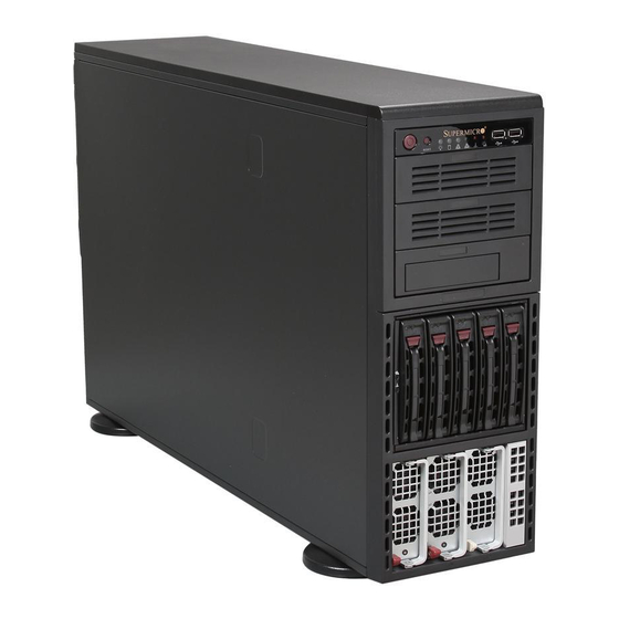
Page 82: Chassis Front And Rear Components
A+ SERVER 4042G-72RF4 USER'S MANUAL Chassis Front and Rear Components Figure 6-1. Front and Rear Chassis Views Power Supplies (2) Control Panel USB Ports (2) Main Power SAS/SATA Drives (5) In Mobile Rack 5.25" Peripheral Drive Bays (3) USB Ports... -
Page 83: Control Panel
Chapter 6: Advanced Chassis Setup Control Panel The front control panel LEDs help monitor the system status. See Chapter 3 for details on the LEDs and buttons. The control panel connects to the JF1 connector on the serverboard to provide system status indications. - Page 84 A+ SERVER 4042G-72RF4 USER'S MANUAL Rotating the Control Panel/Drive Module for Rack Mounting 1. Open the chassis cover. 2. Locate the control panel/drive module and disconnect any cables from the module to any component in the chassis. 3. Push the module release lever to unlock the module. (Figure 6-3) 4.
-
Page 85: Configuring Drives
Chapter 6: Advanced Chassis Setup Configuring Drives The default configuration includes three full size drive trays for removable media drives or hard disk drives, and one storage module with five hard disk drives. Configuring the 5.25" Drive Bays The control panel/drive module includes three 5.25" drive bays under the front control panel. - Page 86 A+ SERVER 4042G-72RF4 USER'S MANUAL Figure 6-5. Add a Hard Drive to the Drive Tray Drive Tray Hard Drive 4. Place the hard drive in the drive tray. The hard drive may not completely fill the tray (Figure 6-5). 5. Secure the hard drive to the tray with four screws from the bottom.
- Page 87 Chapter 6: Advanced Chassis Setup Adding Peripheral Drives to the Drive Bays Replace a drive tray with a peripheral drive. 1. Open the chassis cover. 2. Locate the release tab for the drive tray where you want to place the peripheral drive (Figure 6-4).
-
Page 88: Additional Hard Drives
A+ SERVER 4042G-72RF4 USER'S MANUAL Additional Hard Drives The SC748 chassis accepts a CSE-M35BP Supermicro mobile rack in place of the three bays just under the control panel. This configuration yields a total of ten hot- swap hard drives and no peripheral drives. -
Page 89: Installing Drives In The Storage Module
Chapter 6: Advanced Chassis Setup Installing Drives in the Storage Module Hard drives in the storage module and mobile rack are mounted in drive carriers to simplify their installation and removal. These carriers also help promote proper airflow for the drive bays. Installing Hard Drives 1. - Page 90 A+ SERVER 4042G-72RF4 USER'S MANUAL 3. Remove the screws holding the drive tray to the dummy drive. 4. Place a hard drive in the drive tray (Figure 6-9). Figure 6-9. Installing the Hard Drive Drive Tray SAS/SATA Drive Figure 6-10. Securing Drive 5.
-
Page 91: Expansion Card Setup
Chapter 6: Advanced Chassis Setup Expansion Card Setup After motherboard installation, you can install PCI-E expansion cards. Installing Expansion Cards 1. Locate the release tab on the top of the PCI bracket. 2. Gently apply pressure in the middle of the release tab to unlock the PCI Slot bracket. - Page 92 A+ SERVER 4042G-72RF4 USER'S MANUAL 4. Remove the screw holding the bracket in place and pull the bracket from the chassis (Figure 6-12). Figure 6-12. Remove PCI Card Slot Guard 5. Install your PCI card or other add-on card into the PCI slot bracket and motherboard.
-
Page 93: Installing The Air Shroud
Chapter 6: Advanced Chassis Setup Installing the Air Shroud Air shrouds concentrate airflow to maximize fan efficiency. The SC748 chassis supports two different air shroud designs, one for AMD CPUs and, and another for Intel CPUs. It does not require screws to install. Figure 6-13. -
Page 94: System Fans
A+ SERVER 4042G-72RF4 USER'S MANUAL System Fans Six heavy duty fans provide cooling for the chassis. Three fans are located in the front of the chassis and three fans are in the rear. These fans circulate air through the chassis as a means of lowering the internal temperature of the chassis. -
Page 95: Replacing A Rear Chassis Fan
Chapter 6: Advanced Chassis Setup Replacing a Rear Chassis Fan Rear Fan Replacement Procedure 1. Press the rear fan release tab (Figure 6-16). 2. Pull the fan from the chassis top first. 3. Place the new fan in the chassis bottom first. 4. -
Page 96: Power Supply
A+ SERVER 4042G-72RF4 USER'S MANUAL Power Supply The 4042G-72RF4 server has two 1400 W redundant power supplies. They are auto-switching so they automatically sense and operate at a 100v to 240v input voltage. An amber light is illuminated on the power supply when the power is off. - Page 97 Chapter 6: Advanced Chassis Setup Figure 6-17. Removing a Power Supply Unplug Server Pull the Module Out Using the Handle Press the Release Button 6-17...
- Page 98 A+ SERVER 4042G-72RF4 USER'S MANUAL Notes 6-18...
-
Page 99: Chapter 7 Bios
Chapter 7: BIOS Chapter 7 BIOS Introduction This chapter describes the AMIBIOS™ Setup utility for the H8QG7-LN4F serverboard. The AMI BIOS is stored in a flash chip and can be easily upgraded using a floppy disk-based program. Note: Due to periodic changes to the BIOS, some settings may have been added or deleted and might not yet be recorded in this manual. -
Page 100: Main Menu
A+ SERVER 4042G-72RF4 USER'S MANUAL Main Menu When you first enter AMI BIOS Setup Utility, you will see the Main Menu screen. You can always return to the Main Menu by selecting the Main tab on the top of the screen with the arrow keys. -
Page 101: Advanced Settings Menu
Chapter 7: BIOS Advanced Settings Menu Boot Features Quick Boot If Enabled, this option will skip certain tests during POST to reduce the time needed for the system to boot up. The options are Enabled and Disabled. Quiet Boot If Disabled, normal POST messages will be displayed on boot-up. - Page 102 A+ SERVER 4042G-72RF4 USER'S MANUAL Watch Dog Timer This sets the Watch Dog Timer. Options include Enabled or Disabled. Resume On RTC Alarm This Disables or Enables the RTC Alarm to generate a wake event for S4/ S5 or Legacy Soft Off.
-
Page 103: Advanced Chipset Control
Chapter 7: BIOS HPC Mode This setting Enables or Disables support for P-state HPC Mode. CPB Mode This setting specifies the method of core performance boost enablement to either Auto or Disabled. CPU DownCore Mode This option sets the CPU DownCore Mode for your system. If you change this option then a cold reset is required. -
Page 104: Ecc Configuration
A+ SERVER 4042G-72RF4 USER'S MANUAL Channel Interleaving This option allows you to enable Channel Interleaving in the system. The options are Auto and Disabled. CS Sparing Enable This option will reserve a spare memory rank in each node when enabled. - Page 105 Chapter 7: BIOS IOMMU This setting is used to disable or set the GART size in systems without AGP. Options include Enabled and Disabled. LRDIMM Enhancement Tis setting Enables or Disables LRDIMM enhancement for your system. Memory Performance Mode This sets Memory Performance Mode to either Enabled or Disabled. Memory Timing Parameters This selects the which node's timing parameters to display.
- Page 106 A+ SERVER 4042G-72RF4 USER'S MANUAL IDE/SATA Configuration OnChip SATA Channel This setting allows you to Enable or Disable the OnChip SATA channel. OnChip SATA Type Use this setting to set the OnChip SATA type. Options include Native IDE, RAID, AHCI and Legacy IDE.
- Page 107 Chapter 7: BIOS Use this value if the IDE disk drive support cannot be determined. Select 0 to allow BIOS to use PIO mode 0, which has a data transfer rate of 3.3 MBs. Select 1 to allow BIOS to use PIO mode 1, which has a data transfer rate of 5.2 MBs.
- Page 108 A+ SERVER 4042G-72RF4 USER'S MANUAL PCI Latency Timer This option sets the latency of all PCI devices on the PCI bus. Select a value to set the PCI latency in PCI clock cycles. Options are 32, 64, 96, 128, 160, 192, 224 and 248.
-
Page 109: Remote Access Configuration
Chapter 7: BIOS SuperI/O Configuration Serial 1 Address This option specifies the base I/O port address and Interrupt Request address of serial port 1. Select "Disabled" to prevent the serial port from accessing any system resources. When this option is set to Disabled, the serial port physically becomes unavailable. -
Page 110: Hardware Health Configuration
A+ SERVER 4042G-72RF4 USER'S MANUAL Redirection After BIOS POST Options are Disable (no redirection after BIOS POST), Boot Loader (redirection during POST and during boot loader) and Always (redirection always active). Note that some OS's may not work with this set to Always. - Page 111 Chapter 7: BIOS However for SMCI standard release version BIOS and system monitoring software, motherboard components’ temperatures are NOT required to be displayed. CPU Overheating Alarm (COA) CPU Overheating Alarm (COA) has “Early Alarm” and “Default Alarm” (default) options in the BIOS, and is required to be implemented in all fan speed control modes.
-
Page 112: Acpi Configuration
A+ SERVER 4042G-72RF4 USER'S MANUAL ACPI Configuration ACPI Aware O/S Use this setting to enable or disable ACPI support for the operating system if it supports ACPI. Options include Yes (enable ACPI support) or No (disable ACPI support). ACPI Version Features Use this setting the determine which ACPI version to use. -
Page 113: Ip Address Source
Chapter 7: BIOS IP Address Source This submenu sets the IP address source as either Static or DHCP. Selecting Static allows you to manually set the IP Address, Subnet Mask and Gateway Address. In the field provided here enter the IP address in the decimal form of xxx.xxx. xxx.xxx with xxx having a value of less than 256 and in decimal form only The IP address and current IP address in the BMC are shown. -
Page 114: Security Settings Menu
A+ SERVER 4042G-72RF4 USER'S MANUAL Clear Event Log Selecting this and pressing the Enter key clears the system event log. SR56x0 (RD890S) PCIE Error Log This setting allows you set an error log ofr PCIE errors. Options include Yes or No. -
Page 115: Hard Disk Drives
Chapter 7: BIOS Hard Disk Drives This feature allows you to specify the boot sequence from the list of available hard disk drives. A device that is in parenthesis has been disabled in the corresponding type menu. CD/DVD Drives This feature allows you to specify the boot sequence from the list of available CD/ DVD drives. -
Page 116: Exit Menu
A+ SERVER 4042G-72RF4 USER'S MANUAL Exit Menu Select the Exit tab from AMI BIOS Setup Utility screen to enter the Exit BIOS Setup screen. Save Changes and Exit When you have completed the system configuration changes, select this option to leave BIOS Setup and reboot the computer, so the new system configuration parameters can take effect. -
Page 117: Appendix A Bios Error Beep Codes
Appendix A: POST Error Beep Codes Appendix A BIOS Error Beep Codes During the POST (Power-On Self-Test) routines, which are performed each time the system is powered on, errors may occur. Non-fatal errors are those which, in most cases, allow the system to continue the boot-up process. - Page 118 A+ SERVER 4042G-72RF4 USER'S MANUAL Notes...
-
Page 119: Appendix B System Specifications
Appendix B: System Specifications Appendix B System Specifications Processors Quad AMD Opteron 6000 series (AMD Socket G34 type) processors Note: please refer to our website for details on supported processors. Chipset One AMD SR5690 chipset, one AMD SR5670 chipset and one SP5100 Southbridge chipset BIOS 16 Mb AMI BIOS®... -
Page 120: System Cooling
A+ SERVER 4042G-72RF4 USER'S MANUAL Serverboard H8QG7-LN4F (proprietary SWTX form factor) Dimensions: (LxW) 13" x 16.48" (330 x 419 mm) Chassis SC748TQ-R1K43B (4U rackmount) Dimensions (both): (WxHxD) 17.2 x 7 x 25.5 in. (437 x 178 x 648 mm) Weight Gross (Bare Bone): 85 lbs. -
Page 121: Regulatory Compliance
Appendix B: System Specifications Regulatory Compliance Electromagnetic Emissions: FCC Class B, EN 55022 Class A, EN 61000-3-2/-3- 3, CISPR 22 Class A Electromagnetic Immunity: EN 55024/CISPR 24, (EN 61000-4-2, EN 61000-4-3, EN 61000-4-4, EN 61000-4-5, EN 61000-4-6, EN 61000-4-8, EN 61000-4-11) Safety: CSA/EN/IEC/UL 60950-1 Compliant, UL or CSA Listed (USA and Canada), CE Marking (Europe) California Best Management Practices Regulations for Perchlorate Materials:... - Page 122 A+ SERVER 4042G-72RF4 USER'S MANUAL Notes (continued from front) The products sold by Supermicro are not intended for and will not be used in life support systems, medical equipment, nuclear facilities or systems, aircraft, aircraft devices, aircraft/emergency communication devices or other critical systems whose failure to perform be reasonably expected to result in significant injury or loss of life or catastrophic property damage.
Need help?
Do you have a question about the 4042G-72RF4 and is the answer not in the manual?
Questions and answers