Table of Contents
Advertisement
Quick Links
Advertisement
Table of Contents

Related Manuals for Supero A+ SERVER 4042G-TRF


Summary of Contents for Supero A+ SERVER 4042G-TRF
- Page 1 UPER ® A+ SERVER 4042G-6RF/TRF USER’S MANUAL Revision 1.0b...
- Page 2 The information in this User’s Manual has been carefully reviewed and is believed to be accurate. The vendor assumes no responsibility for any inaccuracies that may be contained in this document, makes no commitment to update or to keep current the information in this manual, or to notify any person or organization of the updates.
- Page 3 Preface Preface About This Manual This manual is written for professional system integrators and PC technicians. It provides information for the installation and use of the A+ SERVER 4042G-6RF/ TRF. Installation and maintenance should be performed by experienced technicians only. The A+ SERVER 4042G-6RF/TRF is a high-end server based on the SC748TS- R1400BP chassis and the H8QG6/i-F, a high-end serverboard which is based on the AMD®...
- Page 4 A+ SERVER 4042G-6RF/TRF User's Manual Chapter 4: System Safety You should thoroughly familiarize yourself with this chapter for a general overview of safety precautions that should be followed when installing and servicing the A+ SERVER 4042G-6RF/TRF. Chapter 5: Advanced Serverboard Setup Chapter 5 provides detailed information on the H8QG6/i-F serverboard, including the locations and functions of connections, headers and jumpers.
- Page 5 Preface Notes...
-
Page 6: Table Of Contents
A+ SERVER 4042G-6RF/TRF User's Manual Table of Contents Chapter 1 Introduction Overview ......................1-1 Serverboard Features ..................1-2 Processors ...................... 1-2 Memory ......................1-2 SAS (AS-4042G-6RF Only) ................1-2 Serial ATA ......................1-2 PCI Expansion Slots ..................1-2 Ethernet Ports ....................1-3 Onboard Controllers/Ports ................ - Page 7 Table of Contents Installing the Chassis Rails ................2-5 Installing the Rack Rails ................. 2-6 Installing the Server into the Rack ..............2-7 Checking the Serverboard Setup ..............2-8 Checking the Drive Bay Setup ..............2-10 Check the Airfl ow ..................2-10 Supplying Power to the System ..............
- Page 8 Using the Adaptec RAID Utility ..............5-27 Installing the RAID Driver During OS Installation ......... 5-27 5-14 Installing Drivers .................... 5-28 Supero Doctor III ................... 5-29 Chapter 6 Advanced Chassis Setup Static-Sensitive Devices .................. 6-1 Precautions ..................... 6-1 Unpacking ....................... 6-1 Control Panel ....................
- Page 9 Table of Contents Advanced Settings Menu ................7-2 Security Settings Menu ................. 7-13 Boot Settings Menu ..................7-13 Exit Menu ...................... 7-14 Appendix A BIOS Error Beep Codes Appendix B Installing Windows Installing the Windows OS for a RAID System ..........B-1 Installing Windows to a Non-RAID System ............
- Page 10 A+ SERVER 4042G-6RF/TRF User's Manual Notes...
-
Page 11: Chapter 1 Introduction
Chapter 1: Introduction Chapter 1 Introduction Overview The A+ SERVER 4042G-6RF/TRF is a high-end server that is comprised of two main subsystems: the SC748TS-R1400BP 4U/tower server chassis and the H8QG6/i-F serverboard. Please refer to our web site for information on operating systems that have been certifi... -
Page 12: Serverboard Features
A+ SERVER 4042G-6RF/TRF User's Manual Serverboard Features At the heart of the A+ SERVER 4042G-6RF/TRF is one H8QG6/i-F quad processor serverboard, which is based on the AMD SR5690/SP5100 chipset. Shown below are the main features of the serverboard. Processors The H8QG6/i-F supports four AMD Opteron 6100 series (Socket G34 type) processors. -
Page 13: Ethernet Ports
Chapter 1: Introduction Ethernet Ports An Intel® network controller is integrated into each of the serverboards to support two Gigabit LAN ports (100/1000Base-T/1000BaseTX, RJ45 output). Onboard Controllers/Ports Onboard I/O backpanel ports on the serverboard include one COM port, a VGA port, two USB ports, a dedicated IPMI LAN port and two Gigabit LAN (NIC) ports. -
Page 14: Server Chassis Features
A+ SERVER 4042G-6RF/TRF User's Manual Server Chassis Features The following is a general outline of the main features of the SC748TS-R1400BP server chassis. System Power The SC748TS-R1400BP features a redundant (two separate power modules) 1400W high-effi ciency power supply with I2C. This power redundancy feature allows you to replace a failed power supply without shutting down the system. - Page 15 Chapter 1: Introduction Figure 1-1. AMD SR5690/SP5100 Chipset: System Block Diagram Note: This is a general block diagram. Please see Chapter 5 for details. CH A0,A1 B0,B1 C0,C1 D0,D1 CH A0,A1 B0,B1 C0,C1 D0,D1 DDR3-1333/1066 DDR3-1333/1066 HT Link G34-SOCKET #4 G34-SOCKET #3 8x DIMM 8x DIMM...
-
Page 16: Contacting Supermicro
A+ SERVER 4042G-6RF/TRF User's Manual Contacting Supermicro Headquarters Address: Super Micro Computer, Inc. 980 Rock Ave. San Jose, CA 95131 U.S.A. Tel: +1 (408) 503-8000 Fax: +1 (408) 503-8008 Email: marketing@supermicro.com (General Information) support@supermicro.com (Technical Support) Web Site: www.supermicro.com Europe Address: Super Micro Computer B.V. -
Page 17: Chapter 2 Server Installation
Chapter 2: Server Installation Chapter 2 Server Installation Overview This chapter provides a quick setup checklist to get your 4042G-6RF/TRF up and running. Following these steps in the order given should enable you to have the system operational within a minimum amount of time. This quick setup assumes that your system has come to you with the processors and memory preinstalled. -
Page 18: Rack Precautions
A+ SERVER 4042G-6RF/TRF User's Manual • Leave approximately 30 inches of clearance in the back of the system to allow for suffi cient airfl ow and ease in servicing. • This product is for installation only in a Restricted Access Location (dedicated equipment rooms, service closets and the like). -
Page 19: Rack Mounting Considerations
Chapter 2: Server Installation Rack Mounting Considerations Ambient Operating Temperature If installed in a closed or multi-unit rack assembly, the ambient operating temperature of the rack environment may be greater than the ambient temperature of the room. Therefore, consideration should be given to installing the equipment in an environment compatible with the manufacturer’s maximum rated ambient temperature (Tmra). -
Page 20: Identifying The Sections Of The Rack Rails
A+ SERVER 4042G-6RF/TRF User's Manual Identifying the Sections of the Rack Rails The optional rackmount kit (MCP-290-00059-0B) includes two rack rail assemblies. Each of these assemblies consist of two sections: an inner fi xed chassis rail (Figure 2-1) that secures to the chassis, and an outer rack rail that secures directly to the rack itself. -
Page 21: Installing The Chassis Rails
Chapter 2: Server Installation Installing the Chassis Rails You will need to remove the top bezel cover and the feet to add rack rails to the chassis. First, remove the top and right covers (top and left covers when standing as a tower chassis) by depressing the latch on the rear lip of the top (side if tower) cover to release it –... -
Page 22: Installing The Rack Rails
A+ SERVER 4042G-6RF/TRF User's Manual Figure 2-3. Installing the Rails to the Chassis Installing the Rack Rails Determine where you want to place the 4042G-6RF/TRF in the rack. (See Rack and Server Precautions in Section 2-3.) Position the fi xed rack rail/sliding rail guide assemblies at the desired location in the rack, keeping the sliding rail guide facing the inside of the rack. -
Page 23: Installing The Server Into The Rack
Chapter 2: Server Installation Installing the Server into the Rack You should now have rails attached to both the chassis and the rack unit. The next step is to install the server into the rack. You should have two brackets in the rack mount kit. -
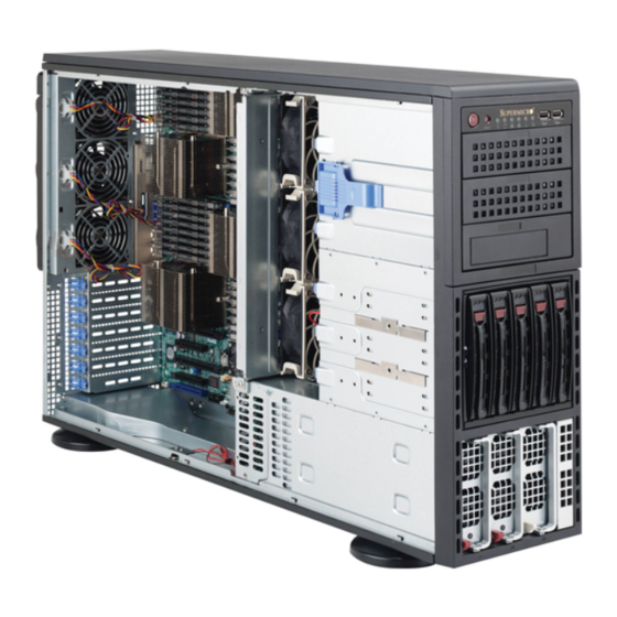
Page 24: Checking The Serverboard Setup
A+ SERVER 4042G-6RF/TRF User's Manual Checking the Serverboard Setup After setting up the the system, you will need to open the unit to make sure the serverboard is properly installed and all the connections have been made (see Figure 2-5). Accessing the Inside of the System If rack mounted, fi... - Page 25 Chapter 2: Server Installation Figure 2-5. Accessing the Inside of the System...
-
Page 26: Checking The Drive Bay Setup
A+ SERVER 4042G-6RF/TRF User's Manual Checking the Drive Bay Setup Next, you should check to make sure the peripheral drives and the SCSI drives and backplane have been properly installed and all connections have been made. Checking the Drive Bay Setup All drives can be accessed from the front of the server. -
Page 27: Chapter 3 System Interface
Chapter 3: System Interface Chapter 3 System Interface Overview There are several LEDs on the control panel as well as others on the SAS drive carriers to keep you constantly informed of the overall status of the system as well as the activity and health of specifi... -
Page 28: Control Panel Leds
4042G-6RF/TRF User's Manual Control Panel LEDs The control panel located on the front of the SC748TS-R1400BP chassis has fi ve LEDs. These LEDs provide you with critical information related to different parts of the system. This section explains what each LED indicates when illuminated and any corrective action you may need to take. -
Page 29: Hdd
Chapter 3: System Interface Indicates IDE channel activity. On the 24042G-6RF this light indicates SAS and/or DVD-ROM drive activity when fl ashing. Power Indicates power is being supplied to the system's power supply units. This LED should normally be illuminated when the system is operating. SAS Drive Carrier LEDs Each SAS drive carrier has two LEDs: •... - Page 30 4042G-6RF/TRF User's Manual Notes...
-
Page 31: Chapter 4 System Safety
Chapter 4: System Safety Chapter 4 System Safety Electrical Safety Precautions Basic electrical safety precautions should be followed to protect yourself from harm and the A+ SERVER 4042G-6RF/TRF from damage: • Be aware of the locations of the power on/off switch on the chassis as well as the room's emergency power-off switch, disconnection switch or electrical outlet. -
Page 32: General Safety Precautions
A+ SERVER 4042G-6RF/TRF User's Manual • The power supply power cords must include a grounding plug and must be plugged into grounded electrical outlets. • This product may be connected to an IT power system. In all cases, make sure that the unit is also reliably connected to Earth (ground). -
Page 33: Esd Precautions
Chapter 4: System Safety • While working on the system, do not wear loose clothing such as neckties and unbuttoned shirt sleeves, which can come into contact with electrical circuits or be pulled into a cooling fan. • Remove any jewelry or metal objects from your body, which are excellent metal conductors that can create short circuits and harm you if they come into contact with printed circuit boards or areas where power is present. -
Page 34: Operating Precautions
A+ SERVER 4042G-6RF/TRF User's Manual • For grounding purposes, make sure your computer chassis provides excellent conductivity between the power supply, the case, the mounting fasteners and the serverboard. Operating Precautions Care must be taken to assure that the chassis cover is in place when the 4042G-6RF/TRF is operating to assure proper cooling. -
Page 35: Chapter 5 Advanced Serverboard Setup
Chapter 5: Advanced Serverboard Setup Chapter 5 Advanced Serverboard Setup This chapter covers the steps required to install the H8QG6/i-F serverboard into the chassis, connect the data and power cables and install add-on cards. All serverboard jumpers and connections are also described. A layout and quick reference chart are included in this chapter for your reference. -
Page 36: Unpacking
A+ SERVER 4042G-6RF/TRF User's Manual Unpacking The serverboard is shipped in antistatic packaging to avoid electrical static discharge. When unpacking the board, make sure the person handling it is static protected. Serverboard Installation This section explains the fi rst step of physically mounting the H8QG6/i-F into the SC748TS-R1400BP chassis. -
Page 37: Connecting Cables
Chapter 5: Advanced Serverboard Setup Connecting Cables Now that the serverboard is installed, the next step is to connect the cables to the board. These include the data (ribbon) cables for the peripherals and control panel and the power cables. Connecting Data Cables The ribbon cables used to transfer data from the peripheral devices have been carefully routed to prevent them from blocking the fl... -
Page 38: I/O Ports
A+ SERVER 4042G-6RF/TRF User's Manual Figure 5-1. Control Panel Header Pins 20 19 Ground No Connection Power LED 3.3V HDD LED FP UID Switch/3.3VSB NIC1 (Link) LED NIC1 (Activity) LED NIC2 (Link) LED NIC2 (Activity) LED OH/Fan Fail/PWR Fail/UID LED Blue_LED_Cathode (UID)/5V SB Power Fail LED 3.3V... -
Page 39: Installing The Processor And Heatsink
Chapter 5: Advanced Serverboard Setup Installing the Processor and Heatsink Exercise extreme caution when handling and installing the processor. Always connect the power cord last and always remove it before adding, removing or changing any hardware components. Installation Procedure Follow the procedures as listed below to install the motherboard into a chassis. Install the processor(s) and the heatsink(s). - Page 40 A+ SERVER 4042G-6RF/TRF User's Manual Use your thumb and your index fi nger to hold the CPU. Locate and align pin 1 of the CPU socket with pin 1 of the CPU. Both are marked with a triangle. Align pin 1 of the CPU with pin 1 of the socket.
-
Page 41: Installing A Passive Cpu Heatsink
Chapter 5: Advanced Serverboard Setup Installing a Passive CPU Heatsink Do not apply any thermal grease to the heatsink or the CPU die -- the required amount has already been applied. Place the heatsink directly on top of the CPU so that the heat sink screws are aligned with the mounting holes on the back plate. -
Page 42: Installing Memory
A+ SERVER 4042G-6RF/TRF User's Manual Installing Memory Exercise extreme caution when installing or removing memory modules to prevent any possible damage. Installing Memory Insert each memory module vertically into its slot, paying attention to the notch along the bottom of the module to prevent inserting the module incorrectly (see Figure 2-1). - Page 43 Chapter 5: Advanced Serverboard Setup Figure 5-4. Installing DIMM into Slot To Install: Insert Notch Notch module vertically and press down until it snaps into place. Pay Front View attention to the align- ment notch at the bottom. Note: Notch should align with the receptive key point on To Remove: Use the slot.
-
Page 44: Dimm Module Population Confi Guration
A+ SERVER 4042G-6RF/TRF User's Manual DIMM Module Population Confi guration For memory to work properly, follow the tables below for memory installation: Per Channel DIMM Populations Options DIMM Type DIMM A DIMM B Max. MHz, Max. MHz, Max. GB/ 1.5V DIMMs 1.35V DIMMs Channel SR or DR... -
Page 45: Adding Pci Add-On Cards
Chapter 5: Advanced Serverboard Setup Adding PCI Add-On Cards A riser card is used to support one standard size (full height full length) PCI expansion card. Installing a PCI Expansion Card Confi rm that you have the correct riser card for your chassis model and the add-on card includes a standard bracket. -
Page 46: Serverboard Details
A+ SERVER 4042G-6RF/TRF User's Manual Serverboard Details Figure 5-5. H8QG6/i-F Layout (not drawn to scale) COM1 FAN7 FAN9 Intel JSMB1 FAN8 82576 JWD1 JPL1 JPG1 JPB1 CPU1 CPU3 JBT1 Battery JWOL1 SP5100 SR5690 JPUSB1 SATA5 SATA4 SATA3 SATA2 JWF1 SATA1 CPU2 CPU4 SATA0... - Page 47 Chapter 5: Advanced Serverboard Setup Description LAN Ports LEDs for the LAN Ethernet ports Dedicated IPMI LAN LEDs for the dedicated IPMI LAN Ethernet port LED for UID Button LED for IPMI Heartbeat LED for Serverboard Power-On Connector Description COM1/COM2 COM1 Serial Port/Header FAN 1-9 Chassis/CPU Fan Headers...
-
Page 48: Connector Defi Nitions
A+ SERVER 4042G-6RF/TRF User's Manual Connector Defi nitions ATX Power 24-pin Connector Pin Defi nitions Pin# Defi nition Pin # Defi nition Power Connectors +3.3V +3.3V A 24-pin main power supply connector(JPW1) -12V +3.3V and three 8-pin CPU PWR connectors (JPW2/JPW3/JPW4) on the motherboard. - Page 49 Chapter 5: Advanced Serverboard Setup Power Fail LED PWR Fail LED Pin Defi nitions The Power Fail LED connection is located on (JF1) pins 5 and 6 of JF1. Refer to the table on the Pin# Defi nition right for pin defi nitions. 3.3V PWR Fail LED Overheat (OH)/Fan Fail/PWR Fail/UID...
- Page 50 A+ SERVER 4042G-6RF/TRF User's Manual Universal Serial Bus Ports Universal Serial Bus Ports Pin Defi nitions (USB0/1, USB6) Two Universal Serial Bus ports (USB 2.0) are USB0 USB1 located beside the Keyboard and Mouse PS2 Pin # Defi nition Pin # Defi nition ports.
- Page 51 Chapter 5: Advanced Serverboard Setup SGPIO SGPIO Header Pin Defi nitions (T-SGPIO1/TSGPIO2) The T-SGPIO1/ T-SGPIO2 (Serial General (3SGPIO1/3SGPIO2)) Purpose Input/Output) headers provide a bus Pin# Defi nition Pin # Defi nition between the SATA controller and the backpane to provide SATA enclosure management Ground Data functions.
- Page 52 A+ SERVER 4042G-6RF/TRF User's Manual Chassis Intrusion Chassis Intrusion Pin Defi nitions A Chassis Intrusion header is located at JL1. (JL1) Attach the appropriate cable to inform you of Pin# Defi nition a chassis intrusion. Battery voltage Intrusion signal Overheat LED Overheat LED Pin Defi...
- Page 53 Chapter 5: Advanced Serverboard Setup Unit Identifi er Button UID Button Pin Defi nitions There is a Unit Identifi er (UID) button on the Pin# Defi nition rear I/O of the board. There is also another Ground UID button located on the control panel. Ground When you push either UID button, both Button In...
-
Page 54: 5-10 Jumper Settings
A+ SERVER 4042G-6RF/TRF User's Manual 5-10 Jumper Settings Connector Pins Explanation of Jumpers To modify the operation of the motherboard, Jumper jumpers can be used to choose between optional settings. Jumpers create shorts between two pins to change the function Setting of the connector. - Page 55 Chapter 5: Advanced Serverboard Setup I2C to PCI-Express Slot C to PCI-Express Slot Jumper Settings C1/JI C2 allows you to enable the I C bus C1/JI to communicate with the PCI-Express slot. Jumper Setting Defi nition For the jumpers to work properly, please set Closed Enabled both jumpers to the same setting.
- Page 56 A+ SERVER 4042G-6RF/TRF User's Manual USB Wake-Up Backpanel USB Wake-Up Enable (JPUSB1) JPUSB1 jumper allows you to "wake up" Jumper Settings the system by pressing a key on the USB Jumper Setting Defi nition keyboard or by clicking the USB mouse of Pins 1-2 Enabled (default) your system.
-
Page 57: 5-11 Onboard Indicators
Chapter 5: Advanced Serverboard Setup 5-11 Onboard Indicators LAN LED (Connection Speed Indicator) LED Color Defi nition LAN1/LAN2 LEDs 10 MHz The Ethernet ports (located beside the VGA Green 100 MHz port) have two LEDs. On each Gb LAN port, Amber 1 GHz one LED blinks to indicate activity while the... -
Page 58: 5-12 Sas And Sata Drive Connections
A+ SERVER 4042G-6RF/TRF User's Manual 5-12 SAS and SATA Drive Connections SATA Ports SATA Ports Pin Defi nitions There are no jumpers to confi gure the SATA (SATA0-SATA5) ports, which are designated SATA0 through Pin # Defi nition SATA5. See the table on the right for pin Ground defi... -
Page 59: 5-13 Enabling Sata Raid
Chapter 5: Advanced Serverboard Setup 5-13 Enabling SATA RAID Now that the hardware is set up, you must install the operating system and the SATA RAID drivers, if you wish to use RAID with your SATA drives. The installation procedure differs depending on whether you wish to have the operating system installed on a RAID array or on a separate non-RAID drive. -
Page 60: Enabling Sata Raid In The Bios
A+ SERVER 4042G-6RF/TRF User's Manual Note: You need to have an external USB fl oppy when building the driver diskette. Window's Vista, Windows 2008 or later Windows OS systems can use a USB stick instead of a fl oppy. Enabling SATA RAID in the BIOS Before installing the Windows Operating System, you must change some settings in BIOS. -
Page 61: Using The Adaptec Raid Utility
Chapter 5: Advanced Serverboard Setup After exiting the BIOS Setup Utility, the system will reboot. When prompted during the startup, press the <CTRL+A> key when prompted to run the Dot- Hill RAID Utility program (see Figure 5-7). Using the Adaptec RAID Utility The Adaptec®... -
Page 62: 5-14 Installing Drivers
A+ SERVER 4042G-6RF/TRF User's Manual Highlight the fi rst "Adaptec RAID" driver shown and press the <Enter> key to install it. Press <Enter> again to continue with the Windows setup. 5-14 Installing Drivers The CD that came bundled with the system contains drivers, some of which must be installed, such as the chipset driver. -
Page 63: Supero Doctor Iii
Chapter 5: Advanced Serverboard Setup Supero Doctor III The Supero Doctor III program is a Web base management tool that supports remote management capability. It includes Remote and Local Management tools. The local management is called SD III Client. The Supero Doctor III program included on the CD-ROM that came with your motherboard allows you to monitor the environment and operations of your system. - Page 64 A+ SERVER 4042G-6RF/TRF User's Manual Figure 5-10. Supero Doctor III Interface Display Screen (Remote Control) Note: Super Doctor III Software Revision 1.0 can be downloaded from our Web Site at: ftp://ftp.supermicro.com/utility/Supero_Doctor_III/. You can also download the Super Doctor III User's Guide at: <http://www.supermicro.com/ manuals/other/SDIII_User_Guide.pdf>.
-
Page 65: Chapter 6 Advanced Chassis Setup
Chapter 6: Advanced Chassis Setup Chapter 6 Advanced Chassis Setup This chapter covers the steps required to install components and perform simple maintenance on the SC748TS-R1400BP chassis. Following the component installation steps in the order given will eliminate most common problems. If some steps are unnecessary, skip ahead to the step that follows. - Page 66 A+ SERVER 4042G-6RF/TRF User's Manual Figure 6-1. Chassis Front View Main Power System Reset System LEDs USB Ports 5.25" Drive Bays (2) Floppy Drive (Optional) 5x SAS/SATA Drive Bays 2x Power Supply Modules...
-
Page 67: Control Panel
Chapter 6: Advanced Chassis Setup Control Panel The front control panel must be connected to the JF1 connector on the serverboard to provide you with system status and alarm indications. A ribbon cable has bundled these wires together to simplify this connection. Connect the cable from JF1 on the serverboard (making sure the red wire plugs into pin 1) to the appropriate comnnector on the front control panel PCB (printed circuit board). - Page 68 A+ SERVER 4042G-6RF/TRF User's Manual Installing a New System Fan. Replace the failed fan with an identical one (available from Supermicro). Install it in the same position and orientation as the one you removed; it should click into place when fully inserted. Check that the fan is working then replace the top/left side chassis panel.
-
Page 69: Removing The Air Shroud
Chapter 6: Advanced Chassis Setup Removing the Air Shroud Under most circumstances you will not need to remove the air shroud to perform any service on the system. However, if you wish to temporarily remove it (the air shroud sould always be in place when the system is operating), please follow this procedure. -
Page 70: Drive Bay Installation
A+ SERVER 4042G-6RF/TRF User's Manual Drive Bay Installation SAS/SATA Drives A total of fi ve SAS/SATA drives may be housed in the SC748TS-R1400BP chassis. The drive IDs are preconfi gured as 0 through 4 (channel A) in order from bottom to top (or from left to right if rackmounted). - Page 71 Chapter 6: Advanced Chassis Setup Figure 6-4. Removing a Drive Carrier Figure 6-5. Mounting a Drive in a Carrier Hard Drive Tray Hard Drive Use caution when working around the SAS/SATA backplane. Do not touch the backplane with any metal objects and make sure no rib- bon cables touch the backplane or obstruct the holes, which aid in proper airfl...
-
Page 72: Installing Components In The 5.25" Drive Bays
A+ SERVER 4042G-6RF/TRF User's Manual Installing Components in the 5.25" Drive Bays Drive Bay Confi guration The 4042G-6RF/TRF has three 5.25" drive bays. Components such as an extra fl oppy drive, IDE hard drives or DVD/CD-ROM drives can be installed into these 5.25"... -
Page 73: Power Supply
Chapter 6: Advanced Chassis Setup Power Supply The A+ SERVER 4042G-6RF/TRF has a redundant 1400 watt power supply consisting of two modules. Each power supply module has an auto-switching capability, which enables it to automatically sense and operate at a 100V - 240V input voltage. - Page 74 A+ SERVER 4042G-6RF/TRF User's Manual Figure 6-7. Removing a Power Supply Module 6-10...
-
Page 75: Chapter 7 Bios
Chapter 7: BIOS Chapter 7 BIOS Introduction This chapter describes the AMIBIOS™ Setup utility for the H8QG6/i-F serverboard. The AMI ROM BIOS is stored in a fl ash chip and can be easily upgraded using a fl oppy disk-based program. Note: Due to periodic changes to the BIOS, some settings may have been added or deleted and might not yet be recorded in this manual. -
Page 76: Main Menu
A+ SERVER 2042G-TRF/6RF User's Manual Main Menu When you fi rst enter AMI BIOS Setup Utility, you will see the Main Menu screen. You can always return to the Main Menu by selecting the Main tab on the top of the screen with the arrow keys. - Page 77 Chapter 7: BIOS is detected, at which point you will need to press the F1 button to re-enter the BIOS setup menu. The options are Enabled and Disabled. Hit 'DEL' Message Display Use this option to Enable or Disable the "Press DEL to run setup" message in POST.
- Page 78 A+ SERVER 2042G-TRF/6RF User's Manual ACPI SRAT Table This option Enables or Disables the building of the ACPI SRAT Table. CPU DownCore Mode This option sets the CPU DownCore Mode for your system. If you change this option then a cold reset is required. Options include Auto Mode, Maximum Core Level, No Leveling, 2 Cores, 4 Cores, 6 Cores, 8 Cores, 10 Cores and 12 Cores.
- Page 79 Chapter 7: BIOS ECC Confi guration ECC Mode This submenu sets the level of ECC protection. Options include Disabled, Basic, Good, Super, Max and User. Selecting User activates the other op- tion for user setting. Note: The "Super" ECC mode dynamically sets the DRAM scrub rate so all of memory is scrubbed in 8-hours.
- Page 80 A+ SERVER 2042G-TRF/6RF User's Manual Legacy USB Support Select "Enabled" to enable the support for USB Legacy. Disable Legacy support if there are no USB devices installed in the system. "Auto" disabled Legacy support if no USB devices are connected. The options are Disabled, Enabled and Auto. IDE/SATA Confi...
- Page 81 Chapter 7: BIOS Use this value if the IDE disk drive support cannot be determined. Select 0 to allow BIOS to use PIO mode 0, which has a data transfer rate of 3.3 MBs. Select 1 to allow BIOS to use PIO mode 1, which has a data transfer rate of 5.2 MBs.
- Page 82 A+ SERVER 2042G-TRF/6RF User's Manual Plug & Play O/S Select Yes to allow the OS to confi gure Plug & Play devices. (This is not required for system boot if your system has an OS that supports Plug & Play.) Select No to allow AMIBIOS to confi...
- Page 83 Chapter 7: BIOS Serial 2 Address This option specifi es the base I/O port address and Interrupt Request address of serial port 2. Select "Disabled" to prevent the serial port from accessing any system resources. When this option is set to "Disabled", the serial port physically becomes unavailable.
- Page 84 A+ SERVER 2042G-TRF/6RF User's Manual Sredir Memory Display Delay Use this setting to set the delay in seconds to display memory information. Options are No Delay, 1 sec, 2 secs and 4 secs. Hardware Health Confi guration CPU Overheat Temperature This setting allows you to specify the type of alarm for CPU overheating.
- Page 85 Chapter 7: BIOS ACPI APIC Support Determines whether to include the ACPI APIC table pointer in the RSDT pointer list. The available options are Enabled and Disabled. Headless Mode Use this setting to enable or disable headless operation mode through ACPI.
-
Page 86: Security Settings Menu
A+ SERVER 2042G-TRF/6RF User's Manual MAC Address In the fi eld provided here enter the MAC address in the hex form of xx.xx. xx.xx.xx.xx with xx in hex form only. The current MAC address in the BMC is shown. Subnet Mask In the fi... -
Page 87: Boot Settings Menu
Chapter 7: BIOS Change User Password Select this option and press <Enter> to access the sub menu, and then type in the password. Boot Sector Virus Protection This option is near the bottom of the Security Setup screen. Select "Disabled" to deactivate the Boot Sector Virus Protection. -
Page 88: Exit Menu
A+ SERVER 2042G-TRF/6RF User's Manual Network Drives This feature allows you to specify the boot sequence from the list of available network drives. A device that is in parenthesis has been disabled in the corresponding type menu. Retry Boot Device This setting allows you to enable or disable auto retry of all boot devices. -
Page 89: Appendix A Bios Error Beep Codes
Appendix A: POST Error Beep Codes Appendix A BIOS Error Beep Codes During the POST (Power-On Self-Test) routines, which are performed each time the system is powered on, errors may occur. Non-fatal errors are those which, in most cases, allow the system to continue the boot-up process. - Page 90 + SE VER 4042G-6RF/TRF User's Manual Notes...
-
Page 91: Appendix B Installing Windows
Appendix B: Installing Windows Appendix B Installing Windows After all hardware components have been installed, you must fi rst confi gure RAID Settings before you install the Windows OS and other software drivers. To confi gure RAID settings, please refer to RAID Confi guration User Guides posted on our web site at www.supermicro.com/support/manuals. -
Page 92: B-2 Installing Windows To A Non-Raid System
+ SE VER 4042G-6RF/TRF User's Manual After the Windows OS Installation is completed, the system will automatically reboot. B-2 Installing Windows to a Non-RAID System Insert Microsoft's Windows OS Setup CD in the CD-ROM drive and the system will start booting up from the CD. Continue with the installation. -
Page 93: Appendix C System Specifi Cations
Appendix C: System Specifi cations Appendix C System Specifi cations Processors Quad AMD Opteron 6100 series (Socket G34 type) processors Note: please refer to our website for details on supported processors. Chipset One AMD SR5690 chipset and one SP5100 Southbridge chipset BIOS 16 Mb AMIBIOS SPI Flash ROM Memory Capacity... - Page 94 A+ SERVER 4042G-6RF/TRF User's Manual Expansion Slots Supports the use of six PCI expansion slots: one PCI-Express x8 slot, one PCI-Express x4 slot, three 64-bit 133 MHz PCI-X slots and one 64-bit 100 MHz PCI-X slot. (The 100 MHz PCI-X slot supports Zero Channel RAID.) Serverboard H8QG6/i-F (proprietary ATX form factor) Dimensions: 16.48"...
- Page 95 Appendix C: System Specifi cations Regulatory Compliance Electromagnetic Emissions: FCC Class B, EN 55022 Class A, EN 61000-3-2/-3- 3, CISPR 22 Class A Electromagnetic Immunity: EN 55024/CISPR 24, (EN 61000-4-2, EN 61000-4-3, EN 61000-4-4, EN 61000-4-5, EN 61000-4-6, EN 61000-4-8, EN 61000-4-11) Safety: CSA/EN/IEC/UL 60950-1 Compliant, UL or CSA Listed (USA and Canada), CE Marking (Europe) California Best Management Practices Regulations for Perchlorate Materials:...
- Page 96 A+ SERVER 4042G-6RF/TRF User's Manual Notes (continued from front) The products sold by Supermicro are not intended for and will not be used in life support systems, medical equipment, nuclear facilities or systems, aircraft, aircraft devices, aircraft/emergency communication devices or other critical systems whose failure to perform be reasonably expected to result in signifi...
Need help?
Do you have a question about the A+ SERVER 4042G-TRF and is the answer not in the manual?
Questions and answers